
Abstract
This study develops a finite element-based simulation of submicrometer crack tip deformation processes in polymers to investigate local toughening effects. An initial study of how these processes interact with stiff inclusions is presented to enable further investigation of particulate toughening. Crack tip and process zone mechanisms, including polymer chain disentanglement, directional chain realignment with consequent anisotropy, and crack propagation, are considered in a dedicated user-defined material law. Such processes are generally homogenized on higher scale continuum levels analyses, but direct simulation can provide insight into toughening mechanisms that have been widely observed but not fully explained. The user material law herein was employed in a parametric study to investigate the relative importance of (1) the extent of local inelastic polymer chain realignment and (2) consequent anisotropic hardening of the realigned polymer chains. In order to explore the interaction of fracture processes with nanometer-scale inclusions, silica particles with varied spacing were also included in the simulations. The interaction between local stress concentration and energy dissipation mechanisms has been quantified. It is shown that in neat polymers, local yielding is the dominant toughening effect accounting for over 90% of the local energy absorption, whereas local stiffening alone would decrease toughness. Stiff inclusions were shown to generally decrease toughness, except in cases where local yielding greatly outweighs local stiffening effects. Roughly 45% increase in toughness was shown for a 250-nm particle spacing that balances the acceleration of elastic failure with the formation of a larger local yield zone size. This demonstrates the utility of employing dedicated material laws to microstructural scale analyses in providing design targets in material design.
Introduction
Epoxies and other polymers exhibit useful mechanical properties with relatively low-specific weights, filling a variety of roles as a lightweight structural material or as an effective matrix in carbon or glass fiber composites. Structural epoxies are highly cross-linked thermosets and therefore generally brittle; their resulting low fracture toughness sometimes makes them unsuitable for structural engineering applications. Nanometer-scale reinforcements are a compelling reinforcing additive in epoxy systems, given their ability to increase strength and toughness at very small volume fractions. Despite much attention and demonstrated benefits, a great deal of work remains to successfully understand the specific toughening mechanisms involved, which can then be exploited for improved material design.
Reducing the scale of reinforcing particles to nanometer dimensions yields disproportionate gains in toughness. 1,2 This enhances the viability of polymers in a wider range of applications and can also improve fatigue performance of fiber-reinforced composite materials. 3 In order to fully realize this potential, nanoparticulate reinforcement must be optimized to produce maximal toughening effects. Such optimization requires furthering the understanding of the physical mechanisms responsible for these improvements. This research investigates specific crack tip deformation mechanisms and microstructural effects which occur on micron and submicron length scales and can interact with inclusions on those same length scales.
Many polymers have been found to exhibit length scale-dependent hardening effects. Such effects have been observed in experiments where nanodiameter indenter tips measure a significantly higher material hardness for very small indentations into the sample. 4 -6 Some researchers have extensively explored the connection between the Frank energy, which quantifies the work required to deform and rotate individual molecular bonds in polymeric chains, and length scale-dependent hardening. 4,5 Subscale processes such as nanometer-sized shear bands in the presence of nanoparticle reinforcements may invoke such small but appreciable modes of energy absorption. The resulting stress fields in the presence of a crack tip may also produce steep stress gradients similar to a nanoindentation experiment.
Likewise, steep stress gradients and shear bands may incur changes in material properties on the length scale of the gradient. 7 Polymer cross-link density has been shown to be an important factor in nanoindentation hardness tests, as well as a determining factor in the size of the shear bands which form during those tests. 8 Although increasing cross-link density in polymers generally leads to decreased toughness, the presence of material defects has been shown to make some level of cross-linking beneficial for toughness. 9
The stress field ahead of the crack tip contains sharp gradients and significantly higher overall stresses than the bulk material. Such a stress state can cause highly localized plastic deformation, even in brittle epoxies. Plastic process zones have been experimentally observed in the vicinity of the crack tips within extremely brittle structural epoxies and have been shown to be important failure mechanisms. 7,10 This process zone is on the order of several microns, which is sufficiently small to satisfy the assumptions of Linear Elastic Fracture Mechanics for continuum level analyses. However, fracture involves small-scale mechanisms within the plastic process zone, such as polymer crazing or the subscale polymer chain interactions which drive crack tip plasticity. One such mechanism is crazing—polymer chain motion and realignment resulting in the nucleation and formation of voids—which often drives polymer failure ahead of the crack tip. Previous research has used the finite element method to investigate the stress field interactions between particulate reinforcements and nearby cracks. 11 -13 However, relatively less research has considered the idea of local processes which may change based on this stress state. 14
The research herein develops a finite element-based simulation of crack tip deformation processes in brittle polymers. The Abaqus commercial finite element analysis (FEA) code is used to simulate fracture events using element deletion to the model crack propagation. A material law is used to represent highly localized crack tip and process zone mechanisms associated with crazing and craze-induced anisotropy, including polymer chain disentanglement, and load-biased chain realignment. These processes occur only at the crack tip in brittle polymers as crack tip opening mechanisms relieving the otherwise singularity of stresses (similarly, plastic dislocation processes will be observed at the crack tip of brittle metals). A parametric study is used to quantify the relative importance of several characteristics of the crack tip processes in terms of energy absorption during fracture. An initial study of how the presence of particulate reinforcements interacts with these crack tip deformation processes is presented to enable the investigation of follow-on studies in nanoparticulate toughening.
Methods
Model configuration
Simulations are designed to mimic continuum-scale classical fracture specimens, in this case single-edge notched tension specimens with simulated domain have widths and heights ranging from 0.5 µm to 1.2 µm along with symmetry boundary conditions. This allows focus upon crack tip behaviors associated with the deformation of a larger specimen. The method here is to develop an approach which explicitly represents mechanisms on this length scale, which will be critical to energy absorption and toughening mechanisms. These are the crack tip opening mechanisms associated with crazing, that is, highly localized polymer chain disentanglement and resulting anisotropic stiffening in the direction of crack opening stresses. Analyses on a higher scale will simply lump all of these mechanisms together in a homogenized toughness value that is completely appropriate for fracture mechanics but unable to explore mechanical differences in crazing behaviors and basic interaction with particulate additives explored herein. Analyses on a smaller length scale would involve quantification of the causes behind differences in crazing behaviors that are parameterized across a likely range in the article herein, that is, the relationship between molecular weight (chain length) and cross-link density on the energy-absorbing mechanisms associated with crack tip opening displacement. Note that these mechanisms will occur at the crack tip even for brittle polymers (just as brittle metals will still have a plastic zone around crack tips in fracture processes). Crazing is well-known to be associated with brittle polymers, as chain mobility is possible on small-length scales. Furthermore, brittle polymers in torsion often exhibit such nonlinear behavior. Thus, the article herein is aimed at exploring important local processes that are simply homogenized in higher scale analyses but will affect fracture, especially with regard to the interaction between crack tip processes and particulate inclusions.
Plane-strain elements are employed in all cases. To simulate loading, a displacement boundary condition is applied to the upper boundary, while the lower and right edges of the specimen are constrained with a roller condition. The precrack, when present, is modeled as a thin row of elements in the refined region which has been removed. Note that at this scale, these simulations represent unique behaviors just around and ahead of the crack tip. To introduce the exploration of particulate reinforcement effects, an example domain with two particles on either side of a crack is shown in Figure 1. The spacing between the particles is varied from 200 µm to 250 µm.
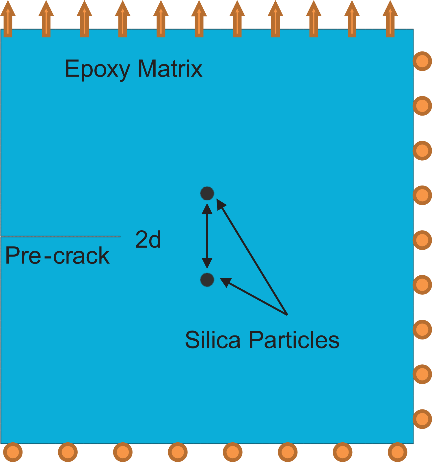
The model used with precrack, particles, and loading conditions.
The Abaqus explicit dynamic solver is used to model loading and fracture events. Although the applied displacement is quasi-static, local snapback deformation occurring in the wake of crack formation can be quite rapid. To accurately simulate this local dynamic response, inertial effects must be considered, that is, dynamic displacements will occur even under quasi-static loading conditions, and a dynamic solver must be used. Velocity scaling was employed in order to expedite computation times; thus, the loading rate was increased without the inclusion of rate effects. This can be done so long as rate effects are not under study and so long as the velocity of the boundary conditions stays well below (less than 1%) of the wave speed of the material. 15 A similar approach is used for problems in which large deformations occur, such as simulations of the deep drawing of manufactured parts.
Crack propagation is modeled by element deletion, which allows any element that surpasses a maximum stress allowable to fail. Thus, there is no artificial limit on crack width, which, instead, scales directly as the stress field itself changes in size. Elements which fail are removed from the simulation by setting their stiffness to zero. To overcome any mesh-dependence, the mesh is significantly refined over a broad area to ensure accurate representation of crack path and crack area, as well as to sufficiently resolve the large crack tip stress gradients. Additionally, a single mesh is used for all cases in the parametric study to ensure that changing the characteristic length of the mesh does not confound the results.
The finite element method enables direct element-by-element tracking of the strain energy in the entire domain, similar to the ability of digital image correlation techniques to map strain fields during experiments. Additionally, an advantage of the finite element method is its ability to track specific energy quantities in each element, such as energy dissipated by inelastic deformation and kinetic energy, during dynamic fracture events. This allows the recoverable energy of the entire domain to be calculated at any point in time, for any crack length. By subtracting the total energy of the system at any instant from the work done on the system up to that point, the energy consumed by fracture can be computed.
The simulation zone is intentionally small to focus in detail on submicron mechanisms. At larger length scales, a single fracture toughness (KIC) or critical strain energy release rate (GIC) is essentially a homogenization of the effects of many mechanisms involved in material damage, for example, material flaws. Because the simulation zone is intentionally small, many additional mechanisms, like material flaws, are not considered; absent of this consideration, macroscopic, homogenized toughness or strength values will neither be predicted nor be appropriated as material laws on this scale. These simulations are intended only to evaluate submicron crack tip processes, their relative importance, and the effect of particulate reinforcement morphologies.
User material law for crack tip deformation behaviors
A user material has been developed in order to(1)simulate crack tip deformation processes, (2) determine the associated energy absorption, (3) account for the highly localized change in mechanical properties that may occur, and (4) account for local anisotropy due to local changes in microstructure at the crack tip. This material law accounts for polymer chain mobility and polymer chain realignment (and the associated stiffness preferential to the loaded direction), such as that which can occur during crazing. Although many thermoset polymers are brittle and do not exhibit plastic behavior at the macroscopic scale, such behavior is present at the micron scale immediately ahead of the crack tip. 16 The developed user material law, in accounting for this behavior, intrinsically assumes a characteristic element size within the finite element simulation. The material law is shown schematically in Figure 2.

User material law.
The user material for crack tip behavior contains three regimes. Regime I is the initial linear elastic response of the material. Regime I ends after exceeding a critical stress (σcr), which is generally the continuum-level yield stress to invoke chain mobility between cross-links, especially as some cross-links are fractured. In regime II, polymer chains slide across each other and realign in the direction of dominant stress (normal to the crack tip) in a plastic deformation process (δεie). The extent of this realignment will be limited by polymer chain length and cross-link density (thus δεie is involved in a parametric study herein). Once complete, fixed polymer chains are again loaded in regime III. As a greater number of chains have been pulled into alignment with the dominant loading, the stiffness of regime III will generally be higher than that of regime I (again dependent on the extent of realignment, thus this stiffness will also be parameterized herein). Chain realignment will also induce significant local anisotropy. Though not illustrated in Figure 2, commensurate loss of off-axis stiffness will accompany the directional stiffening shown in the figure. This off-axis property becomes progressively limited to van der Waals forces between chains rather than covalent bonds within chains. 17 The elastic behavior of regime III continues until the material fails at its ultimate failure strength (σf), that is, the stress required to break the aligned polymer chains. Subsequent behavior can reflect either failing immediately at the ultimate strain limit or can potentially involve progressive stiffness degradation with associated energy absorption (manifested by failing at εdel instead of εf).
When modeling fracture, element size and length scale are accounted by incorporating the characteristic element length into the failure behavior description of the material. The user material law developed herein would manifest this most notably in the amount of inelastic deformation in regime II. Should the length scale increase and the elements be made larger, the regime II and regime III behaviors would all converge to zero (i.e. the macroscopic response). However, such multiscale analyses are not considered herein.
The anisotropic properties of regime III are orientation-dependent. This orientation is not assumed to be normal to the crack tip but is instead determined by the direction of the inelastic strain in regime II. For an unreinforced polymer, this distinction may be trivial, but a particle-reinforced polymer will exhibit complex stress state between crack tip and inclusions. One aim in employing this user material law is for use in simulating fracture in particulate-reinforced polymers, in which case the dominant forces driving microstructural changes will depend on stress field interactions as crack tip stresses combine with particulate stress concentrations.
Parametric study of crack tip deformation processes and interactions with particulate reinforcement
Some of the stress-dependent properties and transition points between regimes of this material law are informed by experimental results 18,19 and known behaviors of polymers. The change in mechanical properties for regime III is adapted from experiments conducted on spun epoxy fibers. 19 Spun epoxy fibers represent a microstructure for which polymer chains are highly aligned along a single axis, which mimics the microstructural state expected in regime III. In a spun epoxy fiber, the polymer chains are more aligned than in cast epoxy.
The amount of inelastic deformation in regime II (δεie) is a variable in the parametric study herein. The modulus and ultimate failure strength all increase to measured values 20 as reflected in Table 1. The increase can vary depending on the nature of the polymer: in a thermoplastic like ultra-high-molecular-weight polyethylene with low cross-linking, the increase can be over 10-fold, but for thermosets like epoxies, a lesser increase of 88% in modulus and 25% in failure strength is observed. In these experiments, the tensile strength of micron-sized epoxy fibers varied greatly due to inevitable flaws in their manufacturing. These flaws were always responsible for failure of the fiber and obscured the “flaw free” failure strength of the fibers. The theoretical failure strength of an amorphous polymer is typically on the order of 10% of the modulus; experimental analysis 19 managed to produce spun fibers of structural epoxy which achieved 65% of that value or 6.5% of the modulus. This strength value is used in the material law developed in this research. The parameters used in the above material law are presented in Table 1.
Material properties informing the user material taken informed by the experiment of Shimada et al. 20

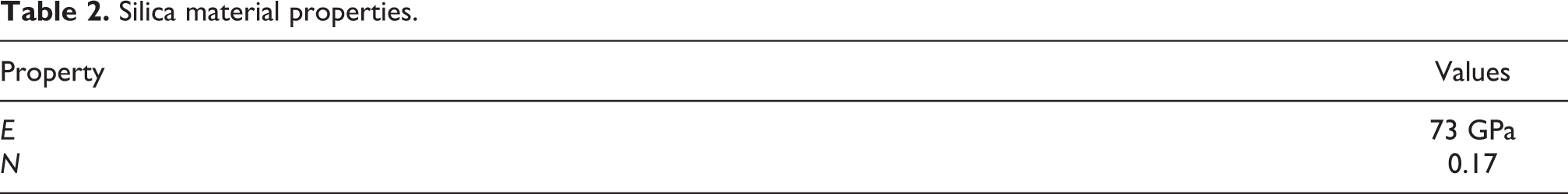
This parametric study is developed to quantify the relative influence of variation in the parameters in the material law (Figure 2) on crack propagation as well as an initial study of the interaction between the crack and particulate inclusions with varied spacing. Simulations are run on the domain, as previously described in Figure 1. In cases where particulate inclusions are considered, the domain focuses on the crack front interactions as the crack approaches two particles; larger domains are the subject of future studies. The particles modeled with the properties are given in Table 2.
Silica material properties.
The inelastic deformation parameter in regime II, δεie, the hardening factor, E2/E1, and the particle spacing are varied. δεie is the amount of inelastic strain allowed in regime II of the material law and represents how much deformation occurs during the realignment of the polymer chains. This quantity also governs how much energy is consumed by the chain realignment process; when δεie is 0, there is no deformation and no corresponding area under the stress–strain curve in regime II. The hardening factor, E2/E1, determines the increase in elastic modulus in the direction of polymer chain realignment. Particulate inclusions are modeled on either side of the propagating crack, and the distance between them is also varied as a parameter. The effects on toughness, stress fields, and character of the crazing zones (inelastic deformation field) are compared. Simulations are run-on cases both with and without particles. The values for material properties are given in Table 3.
Parameter space for crazing law properties.

Verification of stress field predictions
Limited but important verification can be performed to ensure the finite element method and mesh density employed herein can represent the significant stress gradients involved in crack–particle interactions. The simulation methodology for modeling the stress field surrounding a crack and the interaction of the crack with inclusions has been verified by comparing simulated results to known closed-form analytical solutions for the stress field associated with a crack and inclusion in a generic isotropic medium, such as those produced by Erdogan et al. 21 Note that these do not include the additional effects and crack tip processes considered herein, thus this verification is provided to (1) demonstrate the capability of accurately representing stress gradients and (2) demonstrate the representation of a baseline case which is then extended to include the additional physics and representations presented as previously described herein. The geometry used to produce those analytical solutions is shown in Figure 3. A small crack normal to the far field stress is adjacent to a particle but is not aligned with the center of the particle.

Figure, for which the analytical solution produced by Erdogan et al., 21 shows the change in stress intensity factor at a crack tip near a stiffer inclusion.
The analytical solutions compare the stress intensity factor at the crack tips for two cases: the case of a stiffer inclusion, in which the material of the circular particle is given a stiffness higher than the surrounding matrix, and the case of no inclusion, in which the material of the circular particle is given the same stiffness as the surrounding matrix. This increase in stress intensity factor is compared to a finite element simulation for several values of b/a (which determined the proximity of the crack to the stiffer inclusion). To mirror the analytical solutions, the matrix was modeled as a structural epoxy, with a modulus of 4.24 GPa, and the inclusions as stiff glass, with a modulus of 93.9 GPa. An area of the finite element model used to conduct this verification is shown in Figure 4.

An area of the finite element model used in the verification of crack–particle interactions.
Results and discussion
An initial verification assessment has been performed to ensure the capability of adequately representing the complex stress field near the crack tip which approaches stiff particulate reinforcements. Comparison to known, analytical solutions is presented. Next, the results of a parametric study are presented to indicate the relative importance of various features of the material response to the consequent localized fracture toughness of the material, both with and without particulate inclusions near the crack. The morphology of crack propagation and surrounding stress field are also examined.
Verification of crack/particle interaction
The verification consisted of a comparison of a simulated interaction between a stiffer inclusion in an isotropic domain and an oblique crack, as seen previously in Figures 3 and 4. The comparison is drawn between the increases in stress intensity factor due to the introduction of the inclusion. The relative stress intensity factor is mode I stress intensity factor for a crack in the presence of a stiffer inclusion divided by mode I stress intensity factor with no inclusion present. The relative stress intensity factor for the analytical solution and the Abaqus simulation depending on the distance from the crack tip to the particle is graphed in Figure 5. The simulations show the excellent agreement of the trends and good agreement with the actual increase of the stress intensity factor. As can be seen from the results, the stiff inclusion ahead of the crack is partially shielding the crack tip from some stress, that is, the relative stress intensity factor is less than one.

Comparison of analytical to simulated stress intensity factors between a particle and an arbitrarily oriented crack tip.
Parametric study: Stress-dependent property and particle-spacing effects
As discussed in the “Methods” section, several material properties were varied: the inelastic deformation parameter in regime II, δεie, the hardening factor, E2/E1, and the space between particles (if particles are present). In this section, the results of varying the user material law parameters without introducing particles are examined first, then selected parameter combinations are applied to basic cases which include reinforcing particles.
The following figures show the normalized local material toughness for all cases. The baseline control case has no particulate reinforcement present, no inelastic deformation, and no hardening is considered, that is, δεie is zero and the hardening factor (E2/E1) is 1. Thus, the baseline case is purely linear elastic. Toughness values calculated from all other cases are then normalized by this value to strictly consider the effects of the varied parameters on toughness.
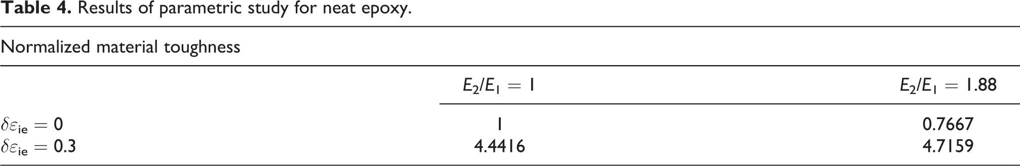
Initial results are shown in Figure 6 considering only the neat epoxy, without any particulate reinforcement. The third column of Figure 6 shows that when crazing-induced inelastic deformation is considered, the associated toughening (over four times) is significant. This indicates that local yielding is itself a major toughening effect, which will have important implications when particulate stress concentrators are introduced. The second column of Figure 6 shows that when only stiffening is introduced, there is an approximately 20% decrease in toughness. This indicates a simple stiffness-induced embrittlement. When both inelastic deformation and stiffening are introduced together, the resulting toughness exceeds the gains made by inelastic deformation alone. Thus in this case, local stiffening due to chain alignment is beneficial rather than detrimental, as the craze yield zone increases, leading to appreciable additional toughening. This can be seen in Figure 6 and Table 4. Two interrelated mechanisms have a net effect: the total energy (area under the stress–strain curve) that a material is capable of absorbing is directly affected by including inelastic deformation and is reduced by a larger linear elastic stiffness. However, the local-stiffening effect increases the size and extent of the plastic region, which invokes significant local energy absorption through inelastic deformation.
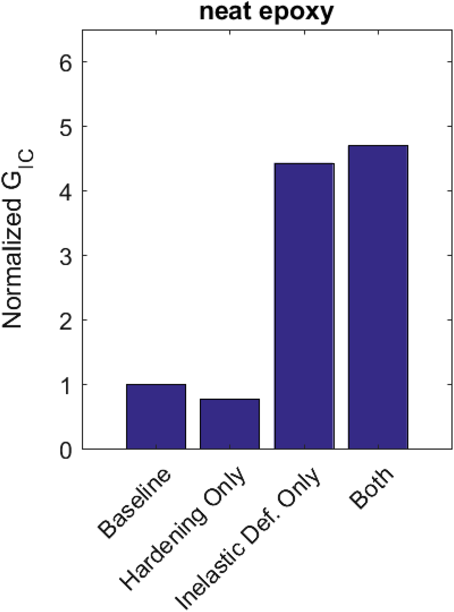
Relative toughening for several configurations of the user material law in a domain of neat epoxy.
Results of parametric study for neat epoxy.
Initial study of toughness including particulate reinforcement with varied spacing
As described, an introductory study of the crack tip and particulate stress field and deformation process interactions has been performed. A study of a various larger arrays of particles as observed in situ in reinforced polymers is outside the current scope and will be the subject of a future work. Figure 8 demonstrates the effect of introducing nanoparticulate reinforcement as two stiff particles on either side of the crack path as shown by normalized toughnesses of all cases. As before, the baseline cases imply no crack tip deformation processes, that is, linear elastic behavior. The dimension given in the legend of the graph refers to the center-to-center distance between the particles. The unreinforced case is also presented here.
It is seen that the presence of particles ahead of the crack tip has little positive or negative effect on toughness when craze-associated crack tip behaviors are not considered (baseline cases). For “hardening only” cases with no local yielding, compounding stress amplifications simply accelerate elastic failure with a detriment to toughness. Only when local yielding is considered, toughening processes are realized (for neat or particulate reinforced cases). It is also noted that toughening behavior is sensitive to the distance between particles, which is consistent with the fact that particle volume fraction influences toughness, and there is a point of diminishing returns. The presence of inclusions was often detrimental to toughness in this initial study including two particles. This is consistent with the general behavior of a stiff inclusion in a brittle matrix. However, it was seen that the local energy absorption increases significantly when local plastic energy absorption outweighs local anisotropic stiffening (column 3 of Figure 7) with a 250-nm particle spacing that balances the acceleration of elastic failure with the formation of larger local yield zone size. It is realized that achieving precise spacing in real materials is not possible, but it also suggests the right combination of materials and dispersion to a target volume fraction can be designed to have a positive effect on toughness.
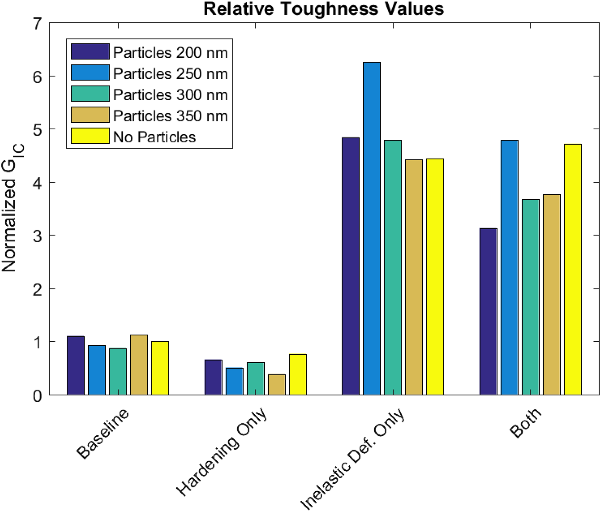
Relative toughening for several configurations of the user material law in an epoxy domain with silica nanoparticles.
Note that to more fully explore, particulate reinforcement is outside the scope of the current paper but will be presented in a follow-on study involving more inclusions as well as variation in the spacing and pattern of an inclusion array. The importance of the study herein is to quantify the contribution of crack tip processes and their interaction with particulates. Including more particles with crack tortuosity and bifurcation will have an impact on toughness requiring dedicated study.
One note on particulate reinforcement is that the synergy between hardening and inelastic deformation in neat polymers is overshadowed. Instead, a hardening effect decreases the overall toughness of cases both with and without any inelastic deformation. However, the detrimental effect of hardening on toughness decreases as the particle spacing increases, that is, the particles appear to be responsible for the weakening mechanism. This could be explained by the particles acting as more powerful stress concentrators than the crazing-induced hardening effect. The particles are nearly 17 times stiffer than the epoxy (compared to the hardening effect only increasing the epoxy stiffness by a factor of 1.88). Note that these results would be quite different if many more particles were included, thus increasing the total plastic zone size. This observation is supported by Figure 8, which compares the cases of modeling inelastic deformation with and without hardening for two nanoparticles spaced 200 nm apart. As the crack approaches the two particles, it shows that the overall area of crazing remains relatively unchanged.

Crazed zone around the propagating crack for an epoxy domain with two silica nanoparticles spaced at 200 nm.
Another clear effect of the nanoparticulate reinforcement is that toughness trends appear to have an inflection point near a 250-nm particle spacing, while this was also the only particle spacing for which toughness was increased by the presence of reinforcing particles. Such length scale-dependent behaviors will be important considerations in the study of particle size effects and consistent with known sensitivity to concentration (volume fraction). For the case of 250-nm particle spacing with crazing-induced local plasticity, toughness increased by roughly 30% versus a neat epoxy .The mechanism responsible for the outlier toughening effect of the 250-nm spaced nanoparticles appears to be analogous to the mechanism responsible for the synergistic effect of inelastic deformation and hardening in the neat epoxy: the parameters converge in such a way as to increase the total area of crazing, and thus increase energy consumption during crack propagation. The 250 nm particles are spaced at an ideal distance to augment the stress field as the crack propagates; further away and the stress concentrating effect of the particles would have a more limited effect, closer and the contribution of the particles would overlap with the zone of material that will craze regardless of their presence. This can be seen in Figure 9, which compares the crazing zone in the 250-nm particle spacing case with the 300-nm particle spacing case. As the crack approaches the particles, the 250-nm spaced particles have a strong influence on the crazing zone and increase its size, whereas the 300-nm spaced particles have at best a mild influence on the crazing zone. This results in more energy consumed to form additional crack length, thus increasing toughness.

The crazed area surrounding the propagating crack for an epoxy domain with inelastic deformation, without hardening, and with two silica nanoparticles.
Conclusions
This research has introduced a finite element-based approach for investigating submicron fracture mechanisms in polymers. At such length scales, many continuum-level material properties are not representative. Traditional FEA methods typically focus on length scales at which macroscopically determined lumped energy parameters, such as fracture toughness, are accurate predictors of fracture behavior. This is completely appropriate for part design but not sufficient to study particle toughening and other microstructural toughening effects. This research has also shown that finite element simulation can be a valuable tool to investigate theoretical toughening mechanisms by enabling them to be separately quantified. The current work has also presented an initial study to quantify the relative importance of crack tip processes and their interaction with reinforcing particulates.
In light of these challenges, a user material law has been employed to reflect crack tip deformation mechanisms associated with local crazing and fracture. It uses material properties grounded in experimental observations which reflect parity with local changes in microstructure due to crazing and polymer chain alignment. This was used in simulation of submicron-scale fracture of brittle structural epoxies, and a preliminary parametric study has been performed to investigate the material law. Additionally, the interaction between inclusions and changing material law parameters was studied. Parametric study was employed to isolate local yielding as the dominant mechanism in neat polymers, whereas anisotropy and stiffening were minor effects.
These mechanisms can interact with cracks and inclusions in ways which are not obvious and difficult to account for without direct simulation and study. In particular, it was found that hardeningcan have a synergistic effect with the inelastic deformation of crazing to increase fracture toughness. Furthermore, it was found that the particulate reinforcement can also have a powerful synergistic effect with the inelastic deformation of crazing, but that this synergy seems sensitive to particulate spacing. Stiff inclusions in a brittle matrix were often detrimental to toughness, but at optimal particulate spacing (or volume fraction), the toughening effect was roughly 45% greater versus the toughness of a neat polymer.
This demonstrates the utility of employing dedicated material laws to microstructural scale analyses in providing design targets in material design, while also showing the need for follow-on studies of particulate-reinforced polymers including multiple particle interactions, crack tortuosity, crack bifurcation, and the complicated stress fields associated with fully dispersed inclusions.
Footnotes
Declaration of conflicting interests
The author(s) declared no potential conflicts of interest with respect to the research, authorship, and/or publication of this article.
Funding
The author(s) received no financial support for the research, authorship, and/or publication of this article.