
Abstract
Resin transfer molding (RTM) is one of the most common processes for producing fiber-reinforced polymer composites. Permeability tensor of the fiber preform is a key material property for satisfactory RTM process. Therefore, it is necessary to acquire a precise permeability tensor from simulation and experiment. In this study, the creeping flow simulation was carried out to obtain the flow field in a unit cell, and Darcy’s law was utilized to compute the permeability tensor. The unit cell for the non-crimp fabrics was defined and constructed, and the permeability was analyzed in the axial, transverse, and thickness directions. The effect of shifted preform layers was also evaluated for more realistic permeability tensor. The predicted and measured results were compared with respect to the fiber volume fraction, fabric pattern, and stacking structure.
Introduction
Resin transfer molding (RTM) is an attractive process because it has great potential to produce complicated polymer composites with good surface quality and dimensional stability. As a result, the molding process has been applied to various industrial composites such as aerospace parts, automotive components, and wind blades. It includes several steps, such as preforming, impregnation, curing, and ejection. On the other hand, the permeability of preforms, an indicator of textile materials to transmit fluids, plays an important role in the RTM process, particularly the resin impregnation step.
Many methods have been investigated to obtain the permeability from analytical calculation, numerical prediction, and experimental measurement. Basically, permeability is defined by Darcy’s law that describes the fluid flow through a porous medium. One of the most popular analytical models is the Kozeny–Carman equation, which has been developed for granular beds with ellipsoidal shape. 1 Since then, a large number of analytical studies have been carried out, but most of them were for unidirectional fiber structures. Also, many numerical studies have been reported. For instance, Sangani and Acrivos numerically analyzed flows in the axial and transverse directions for square and hexagonal packing arrays of filaments. 2 Gebart calculated the permeability by considering different fiber packing and compared with the approximate analytical solution. 3 In addition, simplified models were proposed to predict the permeability of plain-woven fabric using homogenization method. 4 -7 The models using a rectangular unit cell assumed the Stokes equation and the Brinkman equation for inter-tow and intra-tow regions, respectively. However, these methods require an ideally aligned fiber structure, which is not realistic in composite manufacturing.
Recently, much research on carbon non-crimp fabrics (NCFs) has been conducted because of their high performance. 8 -11 Due to the absence of crimping and through-thickness stitching, they have better in-plane mechanical properties and formability than common fabrics with a crimp structure. However, during the layup step of the RTM process, the shifting between two adjacent stacking layers necessarily happens, which results in the blocking and nesting phenomena of fiber tows within the fabrics. Therefore, addressing these effects with a real stacking architecture is a very important issue in numerical simulation.
In this study, the permeability tensor was calculated for three-dimensional NCF fabrics using homogenization method, which is implemented based on finite element method. For numerical analysis, creeping flow was adopted in the in-plane and out-of-plane directions. We also considered the shifting effect between two layers to take into account more realistic textile architecture. Radial and out-of-plane flow tests were performed to measure the relevant permeabilities. Comparison between the predicted values and the measured values was made with respect to the fiber volume fraction, fabric pattern, and stacking structure.
Numerical analysis
The homogenization method used in this study is a computational approach that can replace a heterogeneous material with an equivalent homogeneous material holding the same average properties at both microscale and macroscale. 12 -16 Consequently, it has been widely applied to predict physical properties of materials. In the current study, a rectangular unit cell of the NCF fabrics was extracted for homogenization, and the Stokes equation was calculated for flow. After computing the velocity field, Darcy’s law was used to calculate permeability. The periodic boundary condition was imposed to satisfy the periodicity of the unit cell.
Governing equation
The flow field was obtained using a commercial finite element software, Comsol Multiphysics® (version 5.0). It was assumed that the resin was an incompressible Newtonian fluid, and the fiber bundle was regarded as an impermeable solid. The governing equations are the continuity equation and the momentum equation, that is, the Stokes equation


where
Geometric modeling
Real images and geometrical structures of the carbon fiber NCFs used in this study are shown in Figure 1. Domains of the unit cell with different scales are shown in Figure 2. The mesoscale unit cell was extracted from the macroscale unit cell, and the different mesoscale unit cells were used to predict in-plane and out-of-plane permeabilities. For NCF 0°, the stitch fiber and stabilization thread were considered completely in the in-plane direction. However, when the resin flows in the out-of-plane direction, the fabrics were compressed in thickness direction during the experiment, the stitch fibers at the top and the stabilization thread at the bottom were also compressed and deformed. Therefore, stitch fibers only in the middle were considered for the flow analysis. For NCF 45°, all the stitch fibers were neglected since the size of the stitch fiber is smaller than that in the NCF 0°. It was assumed that the fiber bundles in the unit cell were in contact with one another. The fabric shifting effect between the layers during fabric stacking was considered in the flow analysis for more realistic modeling.
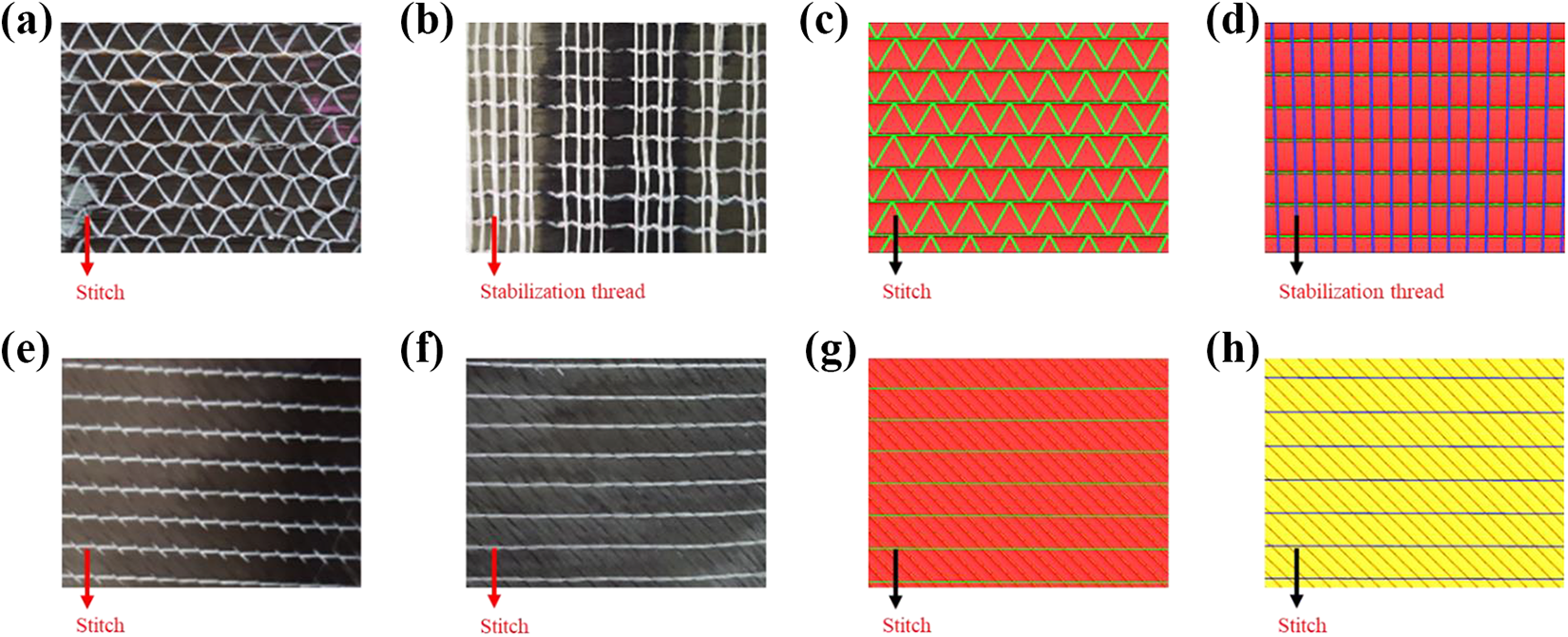
Carbon fiber NCFs used in this study. Photographs of (a) front side and (b) back side for the NCF 0°. (c) Front image and (d) back image of modeled geometry for the NCF 0°. Photographs of (e) front side and (f) back side for the NCF ±45°. (g) Front image and (h) back image of modeled geometry for the NCF ±45°.

Geometry and 3-D mesh for unit cells of the NCF 0° and NCF ±45° without (a and c) and with (b and d) shifting.
Flow analysis for unit cell
Pressure values were imposed as an inlet condition along the axial, transverse, and thickness directions. Periodic flow conditions were applied along the boundary of the unit cell. Using the numerical method described above, velocity profile and pressure field were computed, and then the total flow rate Q in each direction was calculated. The permeability for each direction (Kxx, Kyy, and Kzz) was obtained using the following Darcy’s equation

where A is the cross-sectional area including both fluid and fiber bundles. Diagonal components of the second-order permeability tensor were acquired from equation (3).
Experiments
Two different experiments were performed, and the measured permeability values were compared with the predicted results. 17 -25 The radial flow test was carried out to measure the in-plane permeability of the NCF fabrics. Because it can prevent the edge effect which occurs frequently during the unidirectional experiment, more reliable data may be obtained than employing other methods. Additionally, the out-of-plane flow test was conducted to measure the out-of-plane permeability.
Materials
Fiber preform
Figure 1 shows two different types of the carbon NCFs used in this study. They were the uniaxial and biaxial fabrics. The uniaxial fabric (NCF 0°) was stitched with polyethylene yarns and stabilized with glass fibers. The biaxial fabric (NCF ±45°) was stitched only with polyethylene yarns such that the two uniaxial fabrics were bound to each other in ±45° directions. The carbon fiber was Toray T700SC12K (Toray, Korea).
Resin
Silicone oil (dimethyl siloxane polymer; DC 200F/100CS) was used as an injection resin. Because the silicone oil was a Newtonian fluid with a viscosity of 9.7 × 10⁻² Pa·s, Darcy’s law was applied to calculate the permeability.
Experimental apparatus
Mold design
A transparent mold was designed and built for the measurement of the in-plane permeability as illustrated in Figure 3(a). The top and bottom plates were made of aluminum, and the top plate used to prevent the bending of the transparent plate under pressure had windows. The middle plate was made of transparent poly(methyl methacrylate) (PMMA) to observe the advancement of resin flow.

Schematic illustration of the mold used for the measurement of (a) in-plane and (b) out-of-plane permeabilities.
An additional mold for the measurement of the out-of-plane permeability was constructed as shown in Figure 3(b). The mold was made of steel and consisted of a pair of permeable circular walls to fix fabrics.
Experimental setup
The experimental setup for the radial flow and the out-of-plane flow is illustrated schematically in Figure 4. Compressed nitrogen gas was used for injection of the resin into the mold through the inlet, and the pressure transducers were used to measure pressure at each location. Five layers of the preform were used for all the measurements.

Experimental setup for the measurement of (a and b) in-plane and (c and d) out-of-plane permeabilities.
To obtain the in-plane permeability, square preform layers with a size of 400 × 400 mm2 were placed between the middle and the bottom plates, and the fiber volume fraction was controlled by changing the space between the top and the bottom plates. Resin was injected to the in-plane mold under a pressure of 0.025 MPa, and the pressure at the inlet was measured by the pressure transducer. A digital camcorder was used to record the advancement of the resin flow front.
For the out-of-plane flow experiment, circular preform layers of 12 cm diameter were placed between the permeable walls for uniform flow. The fiber volume fraction was also adjusted by varying the space between the two walls. Pressure was applied to the resin in the range of approximately 0.1–0.2 MPa, and the pressures at the inlet and outlet were measured after saturation. It was assumed that the preform was fully saturated with resin when the mass flow rate became constant, and no air bubble was observed in the silicone oil flowing out of the mold.
Measurement of permeability
The in-plane permeabilities of the two fiber preforms, NCF 0° and NCF ±45°, were determined from unsaturated radial flow experiments at four different fiber volume fractions. The permeability of each case was calculated using the positions of flow front, elapsed time after injection, and measured inlet pressure.
The out-of-plane permeabilities of the NCF 0° and the NCF ±45° were also measured at four different fiber volume fractions in the saturated flow condition. The steady-state flow rate was obtained by collecting and weighing the outflow of silicone oil during the measurement. The pressure gradient was determined using the pressure difference between the inlet and the outlet, and the permeability was calculated with Darcy’s law.
Results and discussion
Figure 5 shows the velocity profile and pressure field of the unit cell when the fiber volume fraction is 0.4. The fluid flow was considered in the axial, transverse, and thickness directions. The velocity profiles show that most of the resin flows through the space between the fiber bundles.

Velocity profile and pressure field without shifting effect for (a) NCF 0° and (b) NCF ±45°.
The velocity profile and pressure field were calculated numerically by considering the fabric shifting effect between the NCF layers (Figure 6). Compared with the case without considering the shifting effect, the velocity profile was changed dramatically, and the average velocity decreased by a half. In particular, the out-of-plane flow of the NCF 0° showed much lower velocities.
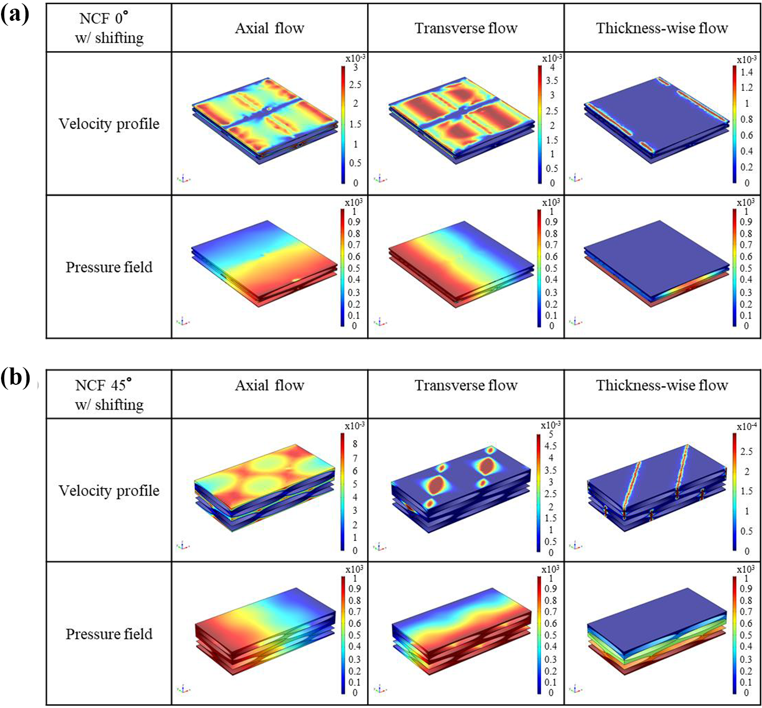
Velocity profile and pressure field with shifting effect for (a) NCF 0° and (b) NCF ±45°.
The permeability of a preform can be calculated using the average velocity and the pressure gradient of the unit cell. Table 1 presents the predicted permeability at each fiber volume fraction. The permeability decreased with increase in the fiber volume fraction, and the out-of-plane permeability of the both fabrics was about two orders of magnitude lower than the in-plane permeability. It is shown that the permeability for the NCF 0° is lower than that for the NCF ±45° in all the directions, and the NCF 0° has more significant shifting effect than the NCF ±45°.
Permeability predicted for (a) NCF 0° and (b) NCF ±45°.
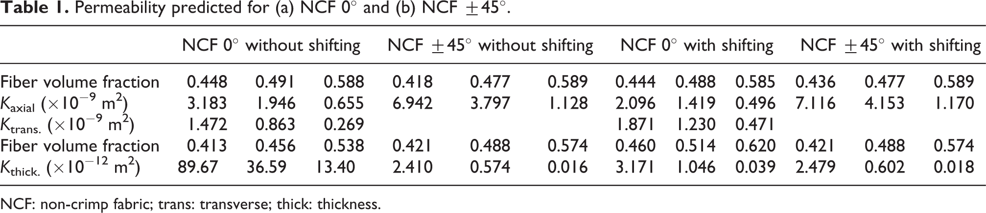
NCF: non-crimp fabric; trans: transverse; thick: thickness.
The flow front advancement through the NCF 0° and NCF ±45° preforms in the radial flow mold was observed with respect to time as shown in Figure 7(a) and (b), respectively. The elliptical flow front through the NCF 0° indicates the anisotropic property of the permeability, whereas the radially symmetric flow front through the NCF ±45° means the isotropic nature of the permeability.

Advancement of the resin flow front for (a) NCF 0° (Vf = 61%) and (b) NCF ±45° (Vf = 69.6%).
To determine the in-plane permeability of the NCF 0°, the terms in the curly brackets of equations (4) and (5) were plotted as a function of time for four different fiber volume fractions as shown in Figure 8. 26 Thereafter, the in-plane permeability of each preform sample was obtained from the slope of the regression line of each graph


where ε is the porosity, t is the elapsed time after injection, xf and yf are the radii of the flow front, x0 and y0 are the radii of the inlet, and ΔP is the pressure difference between the flow front and the inlet.

Linear fitting of the flow front for the NCF 0° in the (a) axial and (b) transverse directions.
The in-plane permeability of the NCF ±45° was also obtained by the same method. Due to the discontinuous resin filling of the NCF ±45° as shown in Figure 7(b), exact observation of the flow front as a function of time was difficult. Therefore, the permeability was determined using the arrival time of the flow front at rf = 17.5 cm, where the flow front was relatively continuous and clear.
The out-of-plane permeabilities of the NCF 0° and the NCF ±45° were calculated using equation (3) 27 and are listed in Table 2. It was revealed that the in-plane and out-of-plane permeabilities of the two fabrics increased as the porosity increased. The in-plane permeability of the NCF ±45° was slightly higher than that of the NCF 0°, while the out-of-plane permeability of the NCF ±45° was much lower than that of the NCF 0°. This large difference in the out-of-plane permeabilities between the two fabrics could be explained by the geometric characteristics of the preforms. That is, although the carbon fibers constituting the fabrics are the same, the macro- and microscopic geometries were different. Because the NCF ±45° consisted of two uniaxial fabrics aligned in ±45° directions, it had more complex flow path than the NCF 0°. The complex flow through the NCF ±45° resulted in relatively high flow resistance through the fabric.
Permeability measured for (a) NCF 0° and (b) NCF ±45°.

NCF: non-crimp fabric; trans: transverse; thick: thickness.
To confirm the numerical results, the predicted permeability was compared with the measured values as shown in Figure 9. Distinction between the numerical and experimental results was small in the in-plane direction, but there was a big difference in the out-of-plane permeability of the NCF 0° when the shift effect was not considered. Such difference decreased when the shift effect was taken into account. This occurred only in the NCF 0°, which means that the NCF 0° was more affected by the shifting effect than the NCF ±45°. The difference between the predicted and the measured out-of-plane permeabilities could be further understood if a nonperiodic stacking was considered to reflect the actual stacking geometry. However, the homogenization method is an efficient way to predict the permeability tensor of fiber preforms with complex structure.

Comparison of the measured and predicted permeabilities of (a) NCF 0° and (b) NCF ±45°.
Conclusion
Numerical and experimental studies were carried out about the permeability of NCF fabrics. The fabric shifting effect between the NCF layers was considered in the numerical analysis. Experimental setups for the measurement of in-plane and out-out-plane permeabilities were designed and constructed. The predicted and measured in-plane permeabilities were in good agreement, but there existed a difference between the measured and predicted values of the out-of-plane permeability due to the simplified geometry of the unit cells employed in the numerical simulation. When the shifting effect was considered in the numerical modeling, the predicted permeability of the NCF 0° showed better agreement with the experimental result than that of the NCF ±45°. Although robust and informative results were provided from the numerical and experimental investigations, it was also shown that more realistic unit cell structure is needed for accurate prediction.
Footnotes
Acknowledgment
The authors are grateful for the supports by Gyeonggi Province, the Ministry of Education, and the Korea government (MSIT).
Declaration of conflicting interests
The author(s) declared no potential conflicts of interest with respect to the research, authorship, and/or publication of this article.
Funding
The author(s) disclosed receipt of the following financial support for the research, authorship, and/or publication of this article: This work was supported by GRRC program of Gyeonggi Province [grant no. GRRC Dankook2016–B03], Basic Science Research Program through the National Research Foundation of Korea (NRF) funded by the Ministry of Education [grant no. 2018R1D1A1B07049173], and by the Korea government (MSIT) [grant no. NRF-2018R1A5A1024127].