
Abstract
Ultra-thin fibre assemblies consisting of cellulose were prepared by means of the electrospinning procedure. In this study, cellulose acetate (CA) was dissolved in dimethylacetamide/acetone (2:1 v/v) and electrospun using a high voltage of 10 and 15 kV and a tip to collector distance of 15 cm. The CA fibre mats were deacetylated and chemically modified by means of a 1,2,3,4-butanetetracarboxylic acid (BTCA)/sodium hypophosphite and a BTCA/(3-aminopropyl)triethoxysilane (APTES) solution. After a thermal treatment at 180°C, Fourier Transform infrared/attenuated reflection spectra of the cross-linked fibre mats confirmed the formation of an ester linkage and an imide moiety, respectively. X-ray diffraction spectra made evident the presence of cellulose II. Thermogravimetric analysis indicated a significant increase in the thermal stability of the chemically modified mats. The water vapour transmission is increased for BTCA/APTES fibre mats.
Introduction
The awareness of sustainable and renewable biomaterials has been extensively increased over the last decades. Thus, investigations also have been focused on cellulose which has some prominent benefits such as low cost, biodegradability, good mechanical properties, nontoxicity and high stability to most organic solvents. Cellulose is a linear chain comprising the constitutional repeating unit cellobiose which consists of two glucose rings joined via a β-1,4-glycosidic bond. The linear cellulose chains are forming microfibrils, which are agglomerations of elementary fibrils. 1,2
In nature, cellulose appears in the form of semi-crystalline fibres with width ranging from 5 μm to 20 μm and length in the range of 0.5 to several millimetres. Natural cellulose can be found in plant cell walls, but it is also produced by tunicates, algae and few bacteria. Nanosized cellulose can be extracted from these natural sources and is used in a wide variety of potential applications. 1,3,4
Nanosized or submicron-sized cellulosic fibres can also be generated by the aid of the electrospinning technique. Electrospinning is the process by which continuous ultra-thin fibres and nanofibres are produced with high surface area to volume ratio. A polymer solution is injected from a needle in the presence of an electric field. When the applied electric field overcomes the surface tension of the liquid, a continuous jet is ejected which upon subsequent solvent evaporation and bending produces nanofibres on the collector surface. 5,6
Cellulose nano or ultra-thin fibres can be produced by means of electrospinning either by applying a solution of cellulose in an appropriate solvent system, 7 such as trifluoracetic acid, 8 N-methyl-morpholine N-oxide/water, lithium chloride/N,N-dimethyl acetamide (DMAc) 9 or ionic liquids. 10,11 Another possibility would be to electrospin a solution of a cellulose derivative, such as cellulose acetate (CA). Subsequently, the as-prepared ultra-thin fibrous mat is converted to regenerated cellulose (RC) by means of a saponification step. Various approaches have been used to endow ultra-fine cellulosic fibre webs with specific properties. 12 Thus, cellulose fibres had been oxidized and sulphated to produce mats which are capable of being used as bone tissue engineering scaffold. 13 Bacterial cellulose was cross-linked by means of glyoxal. 14 To enhance the dyeability, cellulose nanofibres were cationized. 15,16
The goal of the present study was to produce ultra-thin CA fibre webs by means of the electrospinning procedure. The as-prepared fibre mats were subjected to a treatment with an alkaline solution in an attempt to convert the CA fibres into RC. Subsequently, the cellulosic material was chemically modified applying the cross-linking systems 1,2,3,4-butanetetracarboxylic acid (BTCA)/sodium hypophosphite (SHP) and BTCA/(3-aminopropyl)triethoxysilane (APTES).
Experimental
Materials
CA (Mr = 29.000) was supplied by Sigma Aldrich, St Louis, Missouri, USA. DMAc was obtained from Merck Suchardt, Hohenbrunn, Germany. Acetone was purchased from VWR International, Vienna, Austria. APTES (100%) was obtained from Wacker Silicone, Burghausen, Germany. BTCA (>99%) and SHP were purchased from Merck GmbH, Germany. Deionized water was used throughout the investigation. The chemicals were used without further purification.
Apparatus
Electrospinning
The electrospinning apparatus consisted of a syringe pump (Perfusor fm, B. Braun Melsungen, Melsungen, Germany); 5 mL of the polymer solution were fed in a syringe (B/Braun inject 20 mL, B. Braun Melsungen, Melsungen, Germany) which was placed on the syringe holder. The hypodermic needle (diameter 0.60 mm, length 60 mm) and the syringe were connected by means of a plastic tube (Tygon R3607, diameter 1.30 mm; Ismatec, Germany) and appropriate fittings. The feeding rate was 0.1 mL h−1. A voltage in the range of 10 and 15 kV (high voltage (HV)-Quelle, B2electronics, Klaus, Austria) was applied to the needle and after 5 min of electrostatic equilibration, the electrospinning experiments were carried out. A rectangular copper (Cu) collector (25 × 16 cm2) was tightly wrapped with an aluminium foil and used as counter electrode. The tip to collector distance (TCD) was 15 cm.
Analytical characterization
The electrical conductivity of the polymer solutions was determined by the aid of a digital conductivity meter LF 537 (WTW, Weilheim, Germany) using the conductivity cell Tetracon 96 (four-electrode system; WTW). The viscosities of the solutions were measured at 25°C with a Haake Viscotester VT 500 (Haake GmbH, Karlsruhe, Germany) using an MV2 spindle.
To evaluate the surface tension of the polymer solutions, a home-built stalagmometer was used. The surface tension was determined by the drop weight method. 17 Deionized water (DW) was used as reference liquid (s = 72.8 mN m−1, T = 25°C). The average weights of 50 drops were measured. The surface tension was calculated according to the following equation
where m = weight of N drops and N = amount of drops.
To measure the fibre diameter, the fibres were collected on glass slides. Fibre diameter was determined with an optical microscope Olympus CX41 (Olympus Cooperation, Tokyo, Japan). Statistical calculations were performed with the imaging software Stream (Olympus Soft Imaging Solutions GmbH, Münster, Germany). A minimum of 100 fibre diameters were measured for each sample.
The stiffness of the fabrics was determined by means of a Taber Stiffness Tester, Model 112 (Taber Industries, N. Tonawanda, New York, USA) according to ASTM D 1388-R6. Fourier transform infrared (FTIR) spectra were recorded with a Bruker Vector 22 spectrometer (Bruker Cooperation, Karlsruhe, Germany) using a deuterated-triglycine sulfate (DTGS) detector. The spectra were the result of 200 scans. The spectral resolution was 4 cm−1. A PIKE MIRacle™ (Pike Technologies, Madison, Wisconsin, USA) attenuated reflection (ATR) accessory equipped with a diamond ATR crystal was used for all of the analysis shown in this work. A Bruker-AXS D8 (Bruker Cooperation, Karlsruhe, Germany) was used for X-ray diffraction (XRD; parallel beam optics, Cu-target, energy-dispersive counter, sampler changer with rotation). The samples were run with 40 kV, 40 mA, 2–60° θ/2θ, 0.01 step size and 5 s counting time.
Scanning electron microscopy (SEM) micrographs were recorded with an electron micro probe analyzer – JEOL Superprobe 8100 (Joel USA, Incorporation, Peabody, Massachusetts, USA). An acceleration voltage of 15 kV was used. The fibres were sputter-coated with a layer of gold. Thermogravimetric analysis (TGA) measurements were conducted with the thermogravimetric analyser Linseis STA PT1000 (Linseis Messgeräte GmbH, Selb, Germany) (heating rate = 10°C min−1; scan range = 40°C to 900°C). The whiteness index (WI) was calculated according to Commission internationale de l'éclairage (CIE) using the spectrophotometer CM-3610d from Konica Minolta, Japan. The colour data software CM-S100w Spectra Magic NX V1.9 was used for data acquisition. The water vapour transmission (WVT) rate was measured gravimetrically using the water method following ASTM E96. A plastic cup (4 cm diameter, 2.5 cm height, 25 mL) was partially filled with DI (11 mL). A hole (1.5 cm diameter) in the lid of the cup was sealed with the circular test specimen. This cup assembly was placed in a desiccator filled with silica gel. An initial weight was taken of the assembly and then periodically weighed over time.
Methods
Saponification of the CA mat
Various approaches have been adopted to convert CA fibres into RC fibres by means of a saponification treatment. The deacetylation procedure was conducted by soaking the electrospun CA fibre mat in an ethanolic sodium hydroxide (NaOH; c = 0.5 mol L−1) solution for 30 min. Subsequently, the mats were rinsed with DI to obtain neutral pH and dried in a desiccator.
Preparation of the cross-linking solutions
About 7.02-g BTCA (30 mmol) and 3.18-g SHP (30 mmol) were dissolved in 100-mL deionized water. The standard procedure for the synthesis of a BTCA/APTES solution (molar ratio 1/1) in an aqueous medium was as follows: APTES (7.07 mL, 30 mmol) was hydrolysed with hydrogen chloride (c = 0.05 mol L−1, 2.70 mL) in deionized water (20 mL) under magnetic stirring (500 r min−1) in a polyethylene beaker (100 mL) for 15 h at room temperature. Subsequently, 7.02 of BTCA (7.02 g, 30 mmol) were added under vigorous stirring. Stirring was continued for 30 min and the solution was filled to 100 mL with deionized water.
Impregnation of the cellulosic fibre mats with the cross-linking solution
A 4 × 4 cm2 RC was dipped into a BTCA/SHP or BTCA/APTES solution and dried at 105°C for 5 min. This procedure was repeated. The as-prepared samples are denoted as B/S-105 and B/A-105, respectively. Subsequently, the dried specimens were subjected to a curing process at 180°C for 15 min, rinsed with water and dried again at 105°C for 5 min. The fibre mats are denoted as B/S-180 and B/A-180, respectively.
Results and discussion
Preparation of the ultra-thin cellulose fibre mat
Preparation of the CA solution
The properties of the electrospinning solution remarkably influence the morphology (no beading, smooth and uniform structure), the fibre diameter distribution as well as the properties of the ultra-fine fibre mat. The most important physical parameters that have to be perfectly matched to each other are the viscosity, the electrical conductivity and the surface tension. If the viscosity is too low, the phenomenon of electrospraying will be observed resulting in the formation of beads. If the viscosity is too high, polymer motion by the electric field might be prevented. An increase in the conductivity gives rise to a smaller fibre diameter, since an increase in the stretching of the ejected jet takes place. A suitable surface tension is also needed, because the charged solution must overcome the surface tension of the solution. For these reasons, several solvent mixtures were tested in terms of the electrospinnability of CA solutions.
Properties of the CA solution
Therefore, a CA solution with the following parameters had been used for the electrospinning process: 1.70-g CA was dissolved in a mixture of 3.30-mL acetone and 6.60-mL DMAc. The physical parameters of the as-prepared solution were as follows: viscosity (L): 523 mPas, electrical conductivity: 7.48 µS cm−1 and surface tension: 25.8 mN m−1. These values are consistent with those found in the literature. 18,19
Fibre diameter
The electrospinning process was conducted at an HV of 10 and 15 kV applying a TCD of 15 cm. The evaluation of the fibre diameters indicated that an average fibre diameter of 738 ± 130 nm was obtained, when an HV of 10 kV was applied. The average fibre diameter was moderately reduced to 689 ± 128 nm, when an HV of 15 kV was used. This observation is due to the increased stretching of the charged jet. The corresponding fibre diameter distributions are shown in Figure 1(a) (10 kV) and Figure 1(b) (15 kV). Both distributions are very narrow, indicating that uniform fibres of CA were produced.
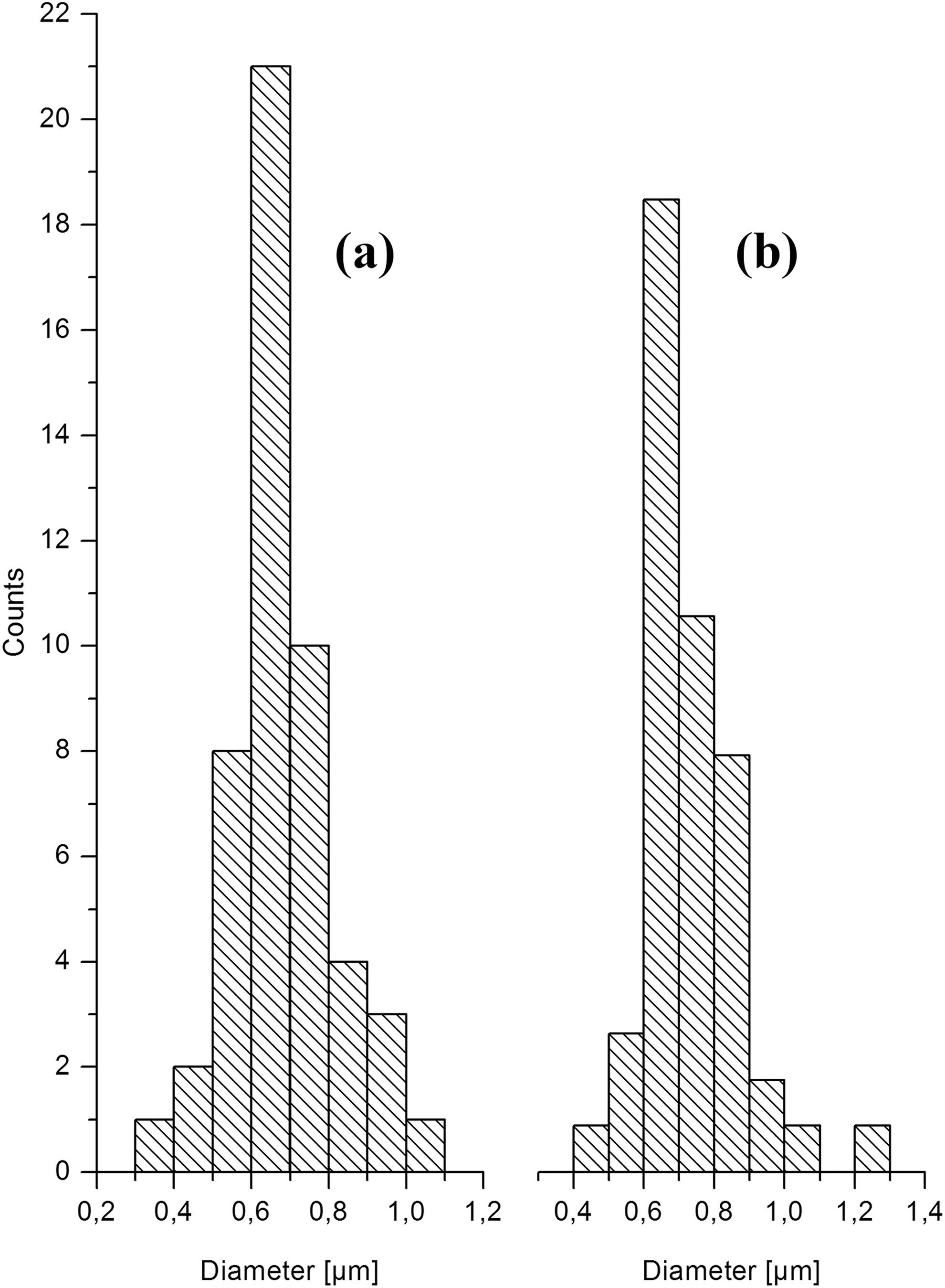
Profiles of the fibre diameter distribution of CA which was electrospun at HV of (a) 10 kV and (b) 15 kV applying a TCD of 15 cm. CA: cellulose acetate; HV: high voltage; TCD: tip to collector distance.
Saponification procedure
To produce ultra-thin cellulose fibre mats, the as-spun CA fibre assemblies were subjected to a saponification treatment as described in the ‘Experimental’ section. Total removal of the acetyl groups was confirmed by FTIR/ATR spectroscopy. Figure 2(a) shows the spectra of the CA fibre and of the deacetylated cellulose fibre matrix. The spectrum of the CA fibre mat shows three prominent absorption bands. The peak at 1743 cm−1 is assigned to the ester carbonyl stretching mode of the ester group. The peak appearing at 1375 cm−1 can be ascribed to the C–CH3 vibration mode of the acetate group, whereas the vibration mode which is observed at 1227 cm−1 is associated with the C–O–C vibration mode of the acetate group. The bands at 1159 to 950 cm−1 are attributed to the C–O stretching and ring vibrational modes of the cellulose. As can be seen, the treatment of the CA fibre mat with the NaOH solution gives rise to the disappearance of the first three absorption peaks, which are characteristic for the acetate group. This observation confirms the completeness of the saponification procedure.

Normalized ATR/FTIR spectra of the CA ultra-thin fibrous mat and the deacetylated fibre mat (a). Normalized ATR/FTIR spectra of RC treated with BTCA, dried at 105°C and subsequently washed (b) indicating that unreacted BTCA has been completely removed by the washing process. ATR: attenuated reflection; FTIR: Fourier transform infrared; CA: cellulose acetate; RC: regenerated cellulose; BTCA: 1,2,3,4-butanetetracarboxylic acid.
Modification of the fibre mat by means of cross-linking agents
A textile fabric is a cloth that has been woven or knitted using natural or synthetic threads or yarns which are placed perpendicular to one another, thus influencing the physical and mechanical properties. In contrast, non-wovens are webs having been fabricated by randomly placing fibres together. 20,21 Due to their structural characteristics, woven materials are stronger than non-wovens. The post-treatment by means of physical–mechanical methods 22,23 or chemical agents 24 -31 results in the formation of a cohesive fabric-like material. The incorporation of functional additives 32 -34 or the formation of non-woven composite materials 35,36 also enables the modification of the physical–mechanical properties.
Various formaldehyde-releasing cross-linking agents are applied to cross-link the cellulosic component of cotton material, thus imparting wrinkle-free performance on the cotton fabric.
Dimethyloldihydroxyethyleneurea (DMDHEU) is the most widely used chemical, since it is effective and inexpensive. Due to environmental awareness, intensive studies are performed to replace DMDHEU by formaldehyde-free cross-linking agents. Polycarboxylic acids, such as BTCA or citric acid in combination with SHP, were studied in detail. 37 -39 The organic–inorganic nanocomposite BTCA/APTES also proved to be a promising zero formaldehyde crease resistant agent for cotton fabrics. 40
Therefore, a BTCA/SHP solution and a BTCA/APTES solution were applied to an RC mat. The as-prepared samples were dried at 105°C for 5 min and subsequently cured at 180°C for 10 min. In an attempt to remove untreated BTCA, the samples were rinsed with deionized water and again dried at 105°C. To confirm that the unreacted BTCA is removed by means of the washing process, an RC sample was finished with a BTCA/SHP solution, dried at 105°C for 5 min and subjected to a washing procedure. Figure 2(b) shows the FTIR/ATR spectra of the BTCA-loaded RC mat and of the washed RC mat. The peak at 1709 cm−1 is assigned to the carbonyl stretching mode of the carboxyl group. This band is no more visible in the washed RC mat.
Stiffness
In an attempt to demonstrate the change of the mechanical properties, the bending stiffness of the chemically modified RC was evaluated (RC: 100%, B/S-180: 262%, B/A-180: 245%). The results make evident that the cross-linking reaction gives rise to an increase in the stiffness properties.
FTIR/ATR
Figure 3(a) shows the FTIR/ATR spectra which were obtained when the RC fibre assembly was impregnated with a BTCA/SHP solution and dried at 105°C (dotted line) and cured at 180°C (solid line). The spectrum of B/S-30-105 shows one prominent band in the carbonyl regime located at 1703 cm−1 which is attributed to the carbonyl stretching mode of the unreacted BTCA. The curing process at 180°C results in the formation of an ester linkage between the carboxylic group of BTCA and the hydroxyl group of the cellulose. As a consequence, the absorption band is shifted to a higher wave number (1730 cm−1).

Normalized ATR/FTIR spectra of RC which has been impregnated with a BTCA/SHP solution, dried at 105°C and cured at 180°C, indicating the formation of an ester linkage between the cellulose and BTCA (a). Normalized ATR/FTIR spectra of RC which has been treated with a BTCA/APTES solution, dried at 105°C and cured at 180°C, indicating the formation of an imide functionality and an ester linkage between the cellulose and BTCA (b). ATR: attenuated reflection; FTIR: Fourier transform infrared; RC: regenerated cellulose; BTCA: 1,2,3,4-butanetetracarboxylic acid; SHP: sodium hypophosphite; APTES: (3-aminopropyl)triethoxysilane.
The dotted line of Figure 3(b) depicts the FTIR/ATR spectrum of the RC sample which was impregnated with a BTCA/APTES solution and dried at 105°C. The stretching vibration mode of the carboxyl group can be observed. The shoulder at 1029 cm−1 can be ascribed to a siloxane mode peak. The thermal treatment at 180°C gives rise to the appearance of three bands at 1778, 1728 and 1695 cm−1. The observation of the bands at 1778 cm−1 (asymmetric carbonyl stretching mode of imide group) and 1695 cm−1 (symmetric carbonyl stretching mode of imide group) proves the presence of an imide functionality. The shoulder at 1728 cm−1 can be related to the ester linkage that had been formed between the free carboxylic acid of BTCA and the hydroxyl groups of the RC fibre. 40,41 The absorption observed at 1151 cm−1 can be assigned to the asymmetric vibration of the bridging C–O–C unit of the cellulose. 42
X-ray diffraction
XRD profiles were recorded to gain a better insight into the structural characteristics of the ultra-thin fibres. Figure 4(a) shows the XRD pattern of the RC fibres, showing three diffraction peaks at 2θ = 12.1°, 20.1° and 21.5°, which are characteristic of cellulose II (man-made cellulosic fibres). 9,43 The diffractogram of the RC mat that had been treated with a BTCA/SHP solution at 105°C is shown in Figure 4(b). Several distinct diffraction peaks, which are attributed to BTCA and SHP, can be observed. These findings make evident that unreacted BTCA and SHP are still incorporated in the cellulosic fibre matrix. The XRD pattern of the RC fibre mat that was treated at 180°C is shown in Figure 4(c). One can notice that almost the same pattern was obtained in comparison with the pristine RC indicating that BTCA has reacted with the hydroxyl groups of the cellulose. No sharp diffraction peaks can be detected in Figure 4(d) (XRD pattern of B/A-105). Thus, it can be concluded that BTCA already has reacted with the amino group of APTES thus forming the corresponding polyamic acid (PAA). Also no significant change of the diffractogram of B/A-180 can be observed (Figure 4(e)). Compared to the XRD pattern of RC, the intensities of the other peaks are lowered. Thus, it can be concluded that the crystallinity of the treated RC fibres are reduced. In addition, the results obtained give evidence that the modification of the cellulose mainly occurs in the amorphous region.

XRD patterns of RC (a), B/S-105 (b), B/S-180 (c), B/A-105 (d) and B/A-180 (e). RC: regenerated cellulose.
Morphology
SEM was used to observe the surfaces of RC (Figure 5(a)) and of RC samples that were impregnated either with a BTCA/SHP solution (Figure 5(b)) or a BTCA/APTES solution (Figure 5(c)). The latter two specimens were cured at 180°C. Figure 5(a) demonstrates that RC ultra-thin fibres with a smooth surface were produced. No beads can be detected. No significant changes in the morphology of the ultra-thin fibres can be observed, when a treatment with BTCA/SHP solution was performed (Figure 5(b)). Figure 5(c) shows the RC fibre matrix which was treated with a BTCA/APTES solution. One can notice the depositions which were formed in the interstices of the ultra-thin fibres.

SEM images of RC (a), B/S-180 (b) and B/A-180 (c). SEM: scanning electron microscopy; RC: regenerated cellulose.
Whiteness index
The chemical modification of cellulosic material at elevated temperatures always results in a reduction of the WI. The WI values of the prepared samples are illustrated in Figure 6. The findings make evident that the curing of B/S-treated RC samples only causes a slight decrease in the WI values. The finishing of the RC samples with B/A solutions leads to a significant reduction of the WI values. This observation can be explained by the fact that the amino-containing units are more inclined to decompose and thus form compounds which decrease the WI values. 44 -46
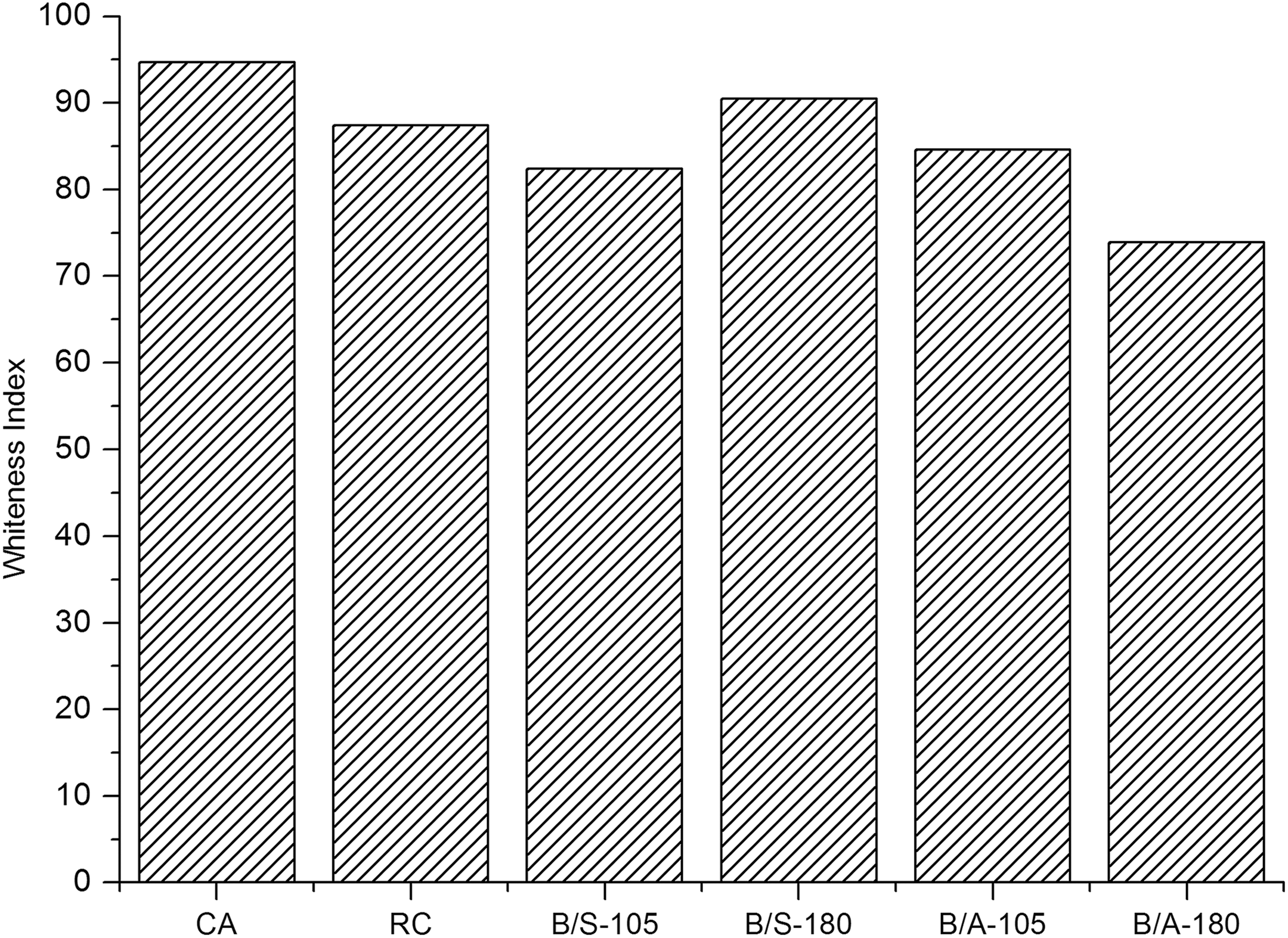
Whiteness index of the ultra-thin fibre assemblies.
Thermogravimetric analysis
To evaluate the thermal properties of the modified ultra-thin RC fibre mats, the thermogravimatric (TG) and the differential thermogravimetric (DTG) curves of the BTCA/APTES-treated samples were recorded. These specimens were selected, since the imide moiety and the incorporation of inorganic units into polymer composite are considered to improve the thermal stability. 47,48 The TG curves are shown in Figure 7(a). The initial onset degradation temperature for the RC fibre mat can be observed at 210°C, for B/A-30-105 at 271°C and for B/A-30-180 at 274°C. The peak temperatures of the corresponding DTG curves indicating the stage of the greatest rate of change on the weight loss curve are illustrated in Figure 7(b). With respect to the RC fibre mat, the peak temperature is located at 273°C, for B/A-30-105 at 310°C and for B/A-30-180 at 318°C. These findings make evident that the thermal treatment with BTCA/APTES endows RC ultra-thin fibre assemblies with an increased thermal stability.

Thermal decomposition profile of RC, B/A-105 and B/A-180 (a). DTG curves of RC, B/A-105 and B/A-180 (b). RC: regenerated cellulose.
Water vapour transmission
WVT is defined as the time rate of water vapour transmission through a unit area of a flat membrane of unit thickness. WVT is generated by a vapour pressure difference between two surfaces with specified humidity and under specified temperature. Good water vapour permeability is very important for protective clothing, since our human body regulates temperature effectively through the evaporation of perspiration. Due to poor WVT, the liquid water may accumulate within the layers of the clothing systems, thus causing discomfort. Therefore, it is of high interest to evaluate the WVT. The results are presented in Figure 8. The findings make evident that the treatment with a BTCA/SHP solution does not affect the WVT compared to RC, whereas the WVT values for a B/A-180 ultra-thin fibre mat are significantly increased.
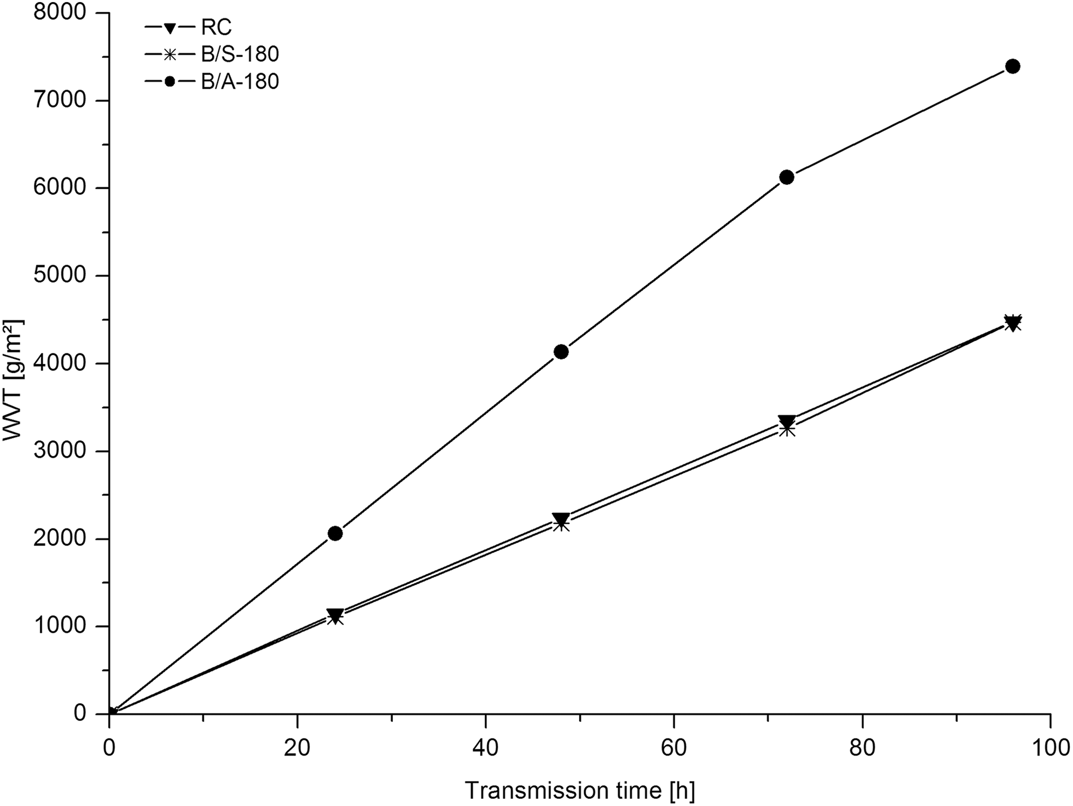
Water vapour transmission of RC, B/S-180 and B/A-180. RC: regenerated cellulose.
Reaction scheme
At an elevated temperature, BTCA forms a five-membered, cyclic anhydride which reacts with the hydroxyl groups of the cellulose, thus forming an ester linkage. 49 -51 Therefore, it can be assumed that the reaction of RC with BTCA/SHP at 180°C results in the formation of ester linkages as shown in Figure 9(a), whereas the reaction of RC with the BTCA/APTES system yields in the formation of a cross-linking unit which contains a five-membered cyclic imide group as depicted in Figure 9(b).

Cross-linking of the hydroxyl groups of the cellulose with BTCA (a) and with the organic–inorganic hybrid which has been formed between BTCA and APTES (b). BTCA: 1,2,3,4-butanetetracarboxylic acid; APTES: (3-aminopropyl)triethoxysilane.
Conclusions
To manufacture a fibrous mat consisting of ultra-thin cellulose fibres, CA was dissolved in dimethylacetamide/acetone (2:1 v/v) and subsequently electrospun using an HV of 10 and 15 kV and a TCD of 15 cm. Hence, the as-prepared CA mats were subjected to a deacetylation process applying an alkaline solution. The non-woven cellulose mats obtained were impregnated with BTCA/SHP and BTCA/APTES solutions and cured at 180°C in an attempt to modify the properties of the ultra-thin fibres. In the case of BTCA/SHP, the presence of an ester linkage was confirmed by means of ATR/FTIR spectra. When BTCA/APTES was applied as cross-linking agent, the formation of an imide moiety was detected. XRD diffractograms confirmed the presence of cellulose II. TGA analysis shows a significant increase in the thermal stability of the chemically modified mats. The water vapour transmission of BTCA/APTES fibre mats was also increased.
Footnotes
Acknowledgements
The authors would like to thank the Testing Institute of the HTL Dornbirn (Austria) for making available textile-physical devices.
Declaration of conflicting interests
The author(s) declared no potential conflicts of interest with respect to the research, authorship, and/or publication of this article.
Funding
The author(s) disclosed receipt of the following financial support for the research, authorship, and/or publication of this article: This work was financially supported by FFG (Österreichische Forschungsförderungs-gesellschaft; project 846932; Endowed Professorship in Advanced Manufacturing).