
Abstract
A double-lap bolted composite joint was designed. In the joint, the base material was woven glass fibre–reinforced epoxy (WGF/Epoxy) composite, and the outer plates were WGF/Epoxy, woven carbon fibre–reinforced epoxy (WCF/Epoxy) and WGF/WCF/Epoxy hybrid composite laminates, respectively. Fundamental mechanical properties of the composite panels were determined. Flexural testing of the designed bolted joints was performed. Scanning electron microscopy was used to compare the damage modes. The interlaminar curves could be divided into different stages. The flexural load–displacement curves had progressive damage characteristics. The strengths of joints with hybrid composite panel as outer plates were between those of pure specimens, and hybrid composites with WGF as contact surface had a positive hybrid effect.
Keywords
Introduction
In the ship engineering field, the strict requirements for structural weight reductions demand an increasing use of composite materials. Composite materials serviced in marine engineering also have outstanding mechanical characteristics. Even though the structure length in a ship could be as long as 200 m, the maximum dimension of an integrative composite structure is limited to 17 m by the manufacturing process such as resin transfer moulding. This is mainly because the resin could not effectively wet the fibres far away from the resin inlet. As a result, joints between different composite components are necessary approaches to manufacture large size shipbuilding. 1 Generally, there are three joining techniques available for composite materials that including adhesive bonding, mechanical fastening and a combination of both. 2 Compared with the others, mechanical fastener joints could be motivated in large size composites shipbuilding.
Composites mechanical joints have many advantages such as no thickness limitations, simple manufacturing process and inspection procedure. 3 -9 However, the main drawbacks are the increased system weight brought by the massive steel bolts. Meanwhile, the significant stress concentration around bolt holes could also compromise the composite joint integrity. 10 In the previous studies, most researchers considered the composite joint geometry (such as laminate thickness, hole diameter and width/hole diameter and end length/hole diameter ratios) on the bolted connections in different composite types with various lay-up styles. For instance, Zhou et al. 11 investigated the geometric parameter influence on the failure response of bolted single-lap composite joints both experimentally and numerically. Ascione et al. 12 studied the failure modes of glass fibre–reinforced plastic bolted laminates. Ahmad et al. 13 concerned with the damage and fracture in woven fabric composite double-lap bolted joints, and they found that the joint finally failed by net-tension damage. Since composite joints are easy to damage in the service lifetime, more efforts should be made to enhance the strength of composite joints.
A hybrid composite is defined to describe a composite where the matrix was reinforced by at least two types of fibres. There are commonly five kinds of hybrid composite structure styles that include intraply, interply, sandwich, intraply/interply and super hybrid composites. 14 This article is mainly focused on the performance of intraply hybrid composites. In intraply hybrid composites, alterable design parameters such as stacking sequence, fibre types and hybrid ratio could make the design of composite structures more flexibly. 15 Hybridization effect allows designers to tailor the composite properties to meet the exact need of the structure. Many researchers have successfully adopted hybridization approach to enhance the mechanical properties and to improve the damage resistance of composites. 16,17 It is found that, by hybridization approach, the composites have enhanced mechanical properties such as interlaminar shear, tensile and compression after impact. In our work, we made the hybrid composites by combination of woven glass fabric cloth (E-glass) layers and woven carbon fabric cloth (T300) layers. Glass fibres are suitable candidate for ship engineering mainly due to their low cost in comparison with carbon fibres. However, the tensile strength of glass fibres is not high. 18 Contrarily, even though carbon fibres possess excellent mechanical performance, they have low compressive-to-tensile strength ratio and low strain-to-failure. 19 Thus, it is possible to incorporate high strength fibres into low strength fibres to enhance the composites strength. In terms of double-lap bolted composite joint configuration and the potential failure modes in Figure 1, the load capability of composite bolted joints is strongly dependent on the base material and the outer plates. Even though mechanical fastener joints reinforced with hybrid composite outer plates may offer suitable properties, research on bolted joints with hybrid composites is very limited.
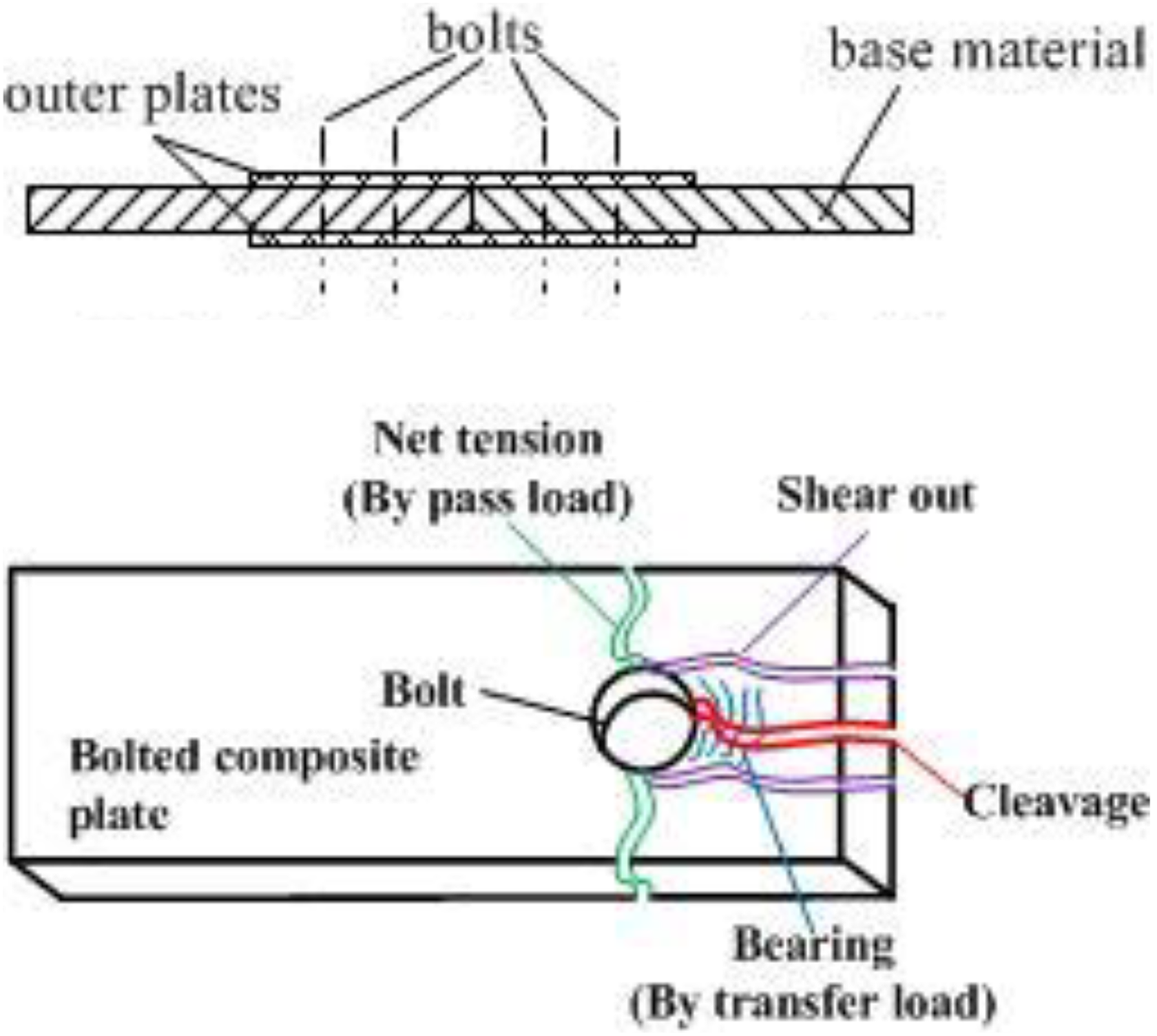
The four typical failure modes of a double-lap bolted composite joint.
As an attempt, we designed a double-lap bolted composite joint to connect two woven glass fibre/epoxy composites parts. The two outer composite plates in the joints were comprised of pure glass fabric, carbon fabric and glass/carbon-reinforced epoxy hybrid composite panels, respectively. The manufacturing process in preparing fibre-reinforced composites was vacuum-assisted resin injection (VARI) processing, and three-point-bending experiments were performed with focus on estimating the strength of the designed joints. The fundamental mechanical performance of the composites was determined experimentally, and mode-I, mode-II and mode-III interlayer fracture toughness tests were carried out to estimate the interlaminate performance. Flexural results of different joints were compared, and failure modes in flexural tests were further analysed with the assistance of scanning electron microscope (SEM) observation.
Joint scheme design, specimen manufacture and testing
Joint scheme description
The designed joint was a two double-lap bolted woven glass fibre–reinforced epoxy (WGF/Epoxy) composite panel fastened by steel bolts. The joint scheme of the designed sketch of the bolted joints is illustrated in Figure 2. In the designed scheme, the thickness of the base WGF/Epoxy is 5 mm, and the length of both sides is 207 mm with width W = 80 mm. The glass fabric cloth in the base plate is 10 ply with fibre stacking sequence of [90°/0°]10. The two outer plates have a thickness of 2.5 mm, and their width is also 80 mm. In the joint, the outer plates could be WGF/Epoxy, woven carbon fibre–reinforced epoxy or hybrid composite panels. The fibre stacking sequence in the outer plates is [90°/0°]5.

Configurations and dimensions of the joints. The outer plates in the test are composed of WCFRP, WGF/Epoxy and hybrid composite panels. WGF/Epoxy: woven glass fibre–reinforced epoxy; WCFRP: woven carbon fiber reinforced plastic composites.
For all the joint types, they were laid symmetrically on both sides from the middle glass fibre panels. Totally, there were 10 steel bolts adopted in the joint scheme with two bolt holes at front and three holes behind. The diameter of the bolt hole was Φ 6 mm, and they penetrated the entire components along the thickness direction. Ply directions in all the outer plates in the joint scheme comprised warp and weft fabrics (90°/0°).
Specimens manufacturing
Manufacturing of composite panels used in the joint specimens was performed via VARI processing. The specific process details of using VARI technology to manufacture composite panels can be found in our previous research work. 20 The epoxy resin is used as the matrix in our experiment. With the reaction of hardening agent and accelerating agent, the resin can be cured at room temperature. During the curing process of epoxy, methyl ethyl ketone peroxide is used as hardening agent, while dimethylaniline is used as accelerating agent. The resin, hardening agent and accelerating agent mass ratio in all the specimens is 100:0.5:0.1. The glass fibre and carbon fibre bundles were obtained from the fabric cloth with surface mass density of 800 and 300 g/m2, respectively. To determine the fundamental mechanical properties of different constituents in the bolted composite joints, we firstly fabricated the specimens for fundamental mechanical tests. The specimen type includes 0°/90° tensile and compression and ±45° tensile and compression, respectively. The specimens were cut from the obtained quadrilateral plate by a diamond saw under water protection. The specimen dimension is in accord with ASTM standards. Specially, we test the interlaminate performance of the researched composites by double cantilever beam (DCB), three-point end notched flexure (3ENF) and mode-III fracture toughness tests. The dimensions of the precrack in the specimens were 25 × 25mm2, and the precrack was located at one end of the specimen.
To make double-lap bolted composite joints with different outer plates, the bolt holes in the joints were made by electrical drilling machine under water as cooling liquid. The location and dimension of the bolt holes were in accord with the configurations in Figure 2. The washers with outside diameter of 18 mm and inner diameter of 8 mm were selected on both sides of the bolts. During the assembling process, we used a torque spanner to fasten the outer plates with WGF/Epoxy panels, and this also ensure that all the bolts have the same pretightening force in the bolt region. Photographs of the specimens after assembled are shown in Figure 3. In this article, we use [C6/G12/C6], [G6/G12/G6], [G3/C3/G12/C3/G3] and [C3/G3/G12/G3/C3] to indicate the double-lap bolted composite joint with pure and hybrid outer plates, as indicated in Figure 3. The hybrid laminates used as outer plates in [G3/C3/G12/C3/G3] and [C3/G3/G12/G3/C3] were produced using woven glass and carbon cloth reinforced epoxy hybrid composites. The total mass of the four types of bolted joints is listed in Table 1. The mass of a single bolt with two washers was 13 g, while one hybrid outer plate had a mass of 57.5 g. In order to quantify hybridization degree in hybrid composites, the hybrid ratio was defined to be the relative ratio of glass fibres to carbon fibres, as follows Assembled composite bolted joint with different outer plates. Total masses of different composite joints.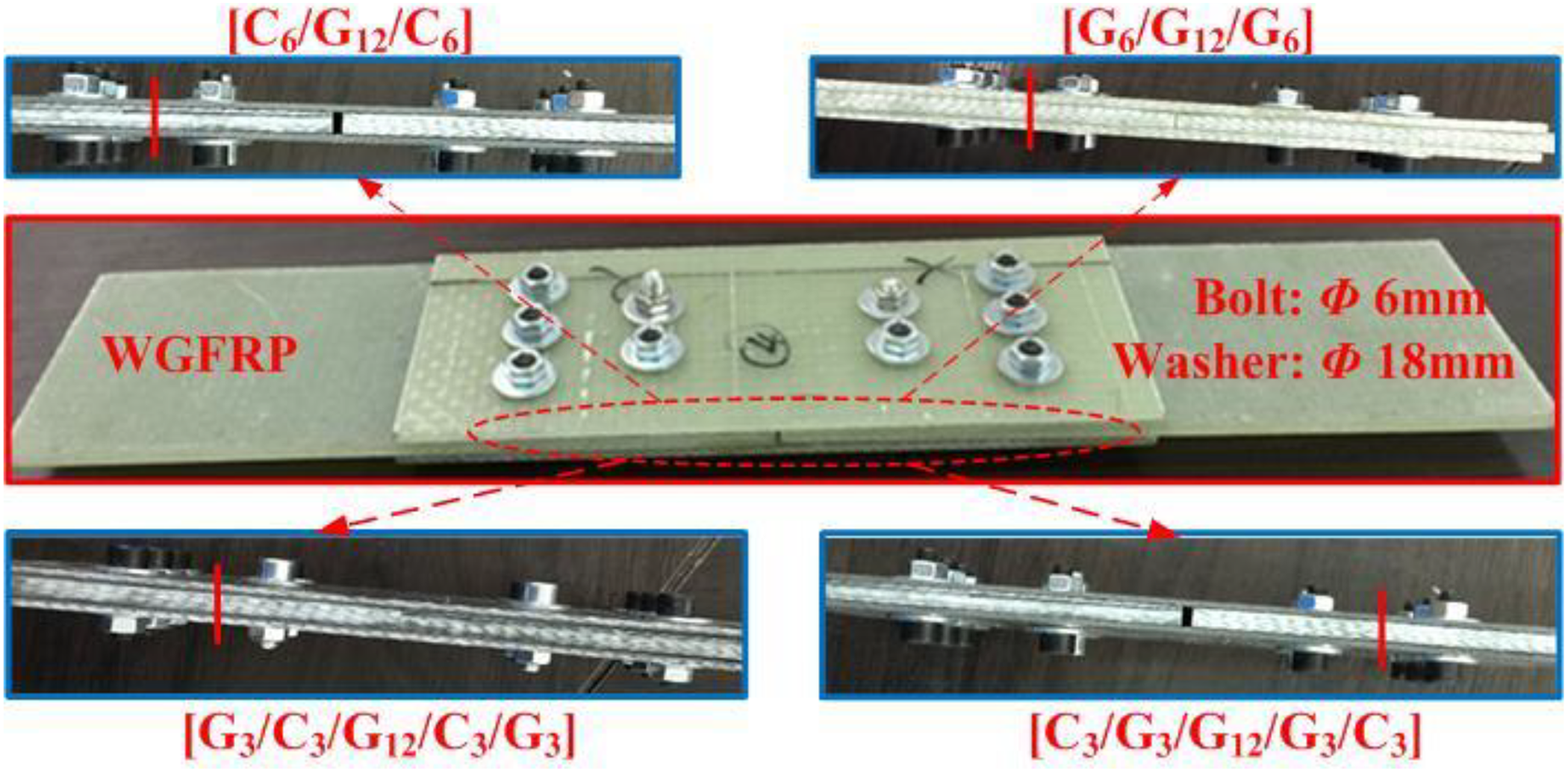


where h g and h c are the thickness of the glass and carbon layers in hybrid composites, while V is their volume fraction. As calculated by equation (1), the hybrid mass ratio in hybrid outer composite laminates is 40:17.
Experimental setup and fundamental mechanical parameter determination
All the mechanical tests were accomplished using an INSTRON-8803 (Grove City, PA, USA) servo-electric testing machine with the maximum load capacity of 500 kN. A data logger was used to record load, displacement and strain data during the test. The dimensions of the transverse (0°), longitudinal (90°) and shear (±45°) tensile specimens were 200 × 20 × 2.5 mm3, and all the calibrating lengths in the three types of test are 100 mm. In the compressive tests, the dimension of the three specimens is 160 × 20 × 2.5 mm3 with calibrating length of 80 mm. To evaluate the interlaminar fracture toughness (ILFT), DCB, 3ENF and mode-III tests were carried out according to standard ASTM-D5528. In DCB test, a pair of hinges was attached on the upper and lower surface of the specimens by strong glue. During the experiment, they were used as fixture with the upper one carrying external load and the lower one fixed on the machine. Tests stopped when the displacement reached 25 mm. The applied load and the crack opening displacement were recorded. 3ENF test was performed in flexural mode. Mode-III fracture toughness test was also carried out with the help of a pair of steel chucks. In the three-point-bending test of the designed bolted joints, flexural span of the test is 260 mm, and diameter of cross-head is 25 mm. Cross-head was applied at mid-span of the specimen with displacement speed of 2 mm/min. All the tests were performed at 25°C.
Microscopic morphology observation
To evaluate the micro damage morphology of the bolted joint specimens, the microstructure of the hybrid out plates is observed by SEM (EVO MA 15, Zeiss). Specimens adopted in SEM test are selected from the hybrid composites around damage region in the joints. Observations are carried out with focus on the glass fabric and carbon fabric in hybrid composite panels, respectively.
Results and discussion
Fundamental mechanical test results of WGF/epoxy specimens
Figure 4(a) to (e) shows the representative stress–strain curves of WGF/Epoxy composites at room temperature in (a) 90o90°/0° tensile test, (b) ±45° tensile test, (c) 90°/0° compression test, (d) ±45o compression test and (e) three-point-bending test, respectively. Together in the figure, we give the damage pattern of the finial specimens after mechanical tests. The elastic modulus (E), strength (S) and failure strain (ε max) of WGF/Epoxy laminates calculated from Figure 4 are listed in Table 2. The three parameters were measured by using longitudinal, transverse and ±45° tensile and compression. Elastic modulus was calculated from the initial slope of the stress–strain curve. The tensile/compression strengths of the woven fabric composite plates were determined by dividing the failure load to the cross-sectional area of the specimens, respectively. The following three formulas were utilised to calculate the flexural performance of the WGF/Epoxy laminates

Stress–strain curve of WGF/Epoxy obtained in different experimental tests. WGF/Epoxy: woven glass fibre–reinforced epoxy.
Elastic modulus, strength and failure strain of WGF/Epoxy in experimental tests.

WGF/Epoxy: woven glass fibre–reinforced epoxy.


where L is the support span and m is the slope of the initial stage of load–displacement curve, while b and d is the width and depth of tested beam, respectively.
As is well known, tensile properties of a composite material are mainly dependent on fibre strength, modulus, fibre length and orientation, fibre/matrix interfacial bonding and fibre content. 21 In Figure 5, we give the microstructure of the in-plane appearance of woven glass fabric–reinforced epoxy resin composites in this work. Generally, in Figure 4, it can be found that the tensile curves of 90 and 0° specimens and +45° and −45° specimens are very similar due to the in-plane symmetry characteristic of woven fabric cloth in Figure 5. In Figure 4(a), the stress of 90°/0° tensile specimen increases linearly with strain until completely damaged at a specific strain value, and the damage morphology of tensile specimens shows a flat macroscopic fracture characteristic. The strength of 90°/0° tensile specimen is nearly the same (around 487 MPa), with E = 11.8 GPa and an average failure stain of 4.97%. As a comparison, in terms of ±45° tensile in Figure 4(b), the stress curves appear to be an approximately linear relationship initially, and then they perform plastic yielding with increasing strain. Damage pattern of ±45° tensile specimens clearly shows that glass fibres breaking is the main damage mode under shear stress generated by tensile load. The modulus, strength and failure strain of the specimen are 4.82 GPa, 108.4 MPa (average) and 24.24%, respectively. We found that failure strain of ±45° tensile specimens is much higher than 90°/0° tensile due to their better deformation capacity under tensile mode. For 90°/0° tensile specimens, they exhibit lower deformation at break and higher strength than ±45° tensile specimens. This is because the woven fabrics are tightly bonded in WGF/Epoxy laminates along warp and weft direction. The stretching nature of ±90° fabrics makes them breaking at different times as each fibre can stretch independently and break individually when reaching to the breaking strain. This is also explained that 90°/0° tensile specimen showed higher tensile modulus. In compression test, typical stress–strain curves of all the specimens firstly linearly increase and then slightly decrease to minimum value in Figure 4(c) and (d). The damage mode in 90°/0° specimens is mainly the shear delamination damage of the laminates under compress load. A large delamination area was existing in ±45° compress specimens. E, S and ε max of the 90°/0° compression specimens are 10.04 GPa, 59.76 MPa and 0.38%, while the three parameters of the ±45° compression specimens are 6.23 GPa, 31.02 MPa and 0.35%, respectively. The flexural stress–strain curve of WGF/Epoxy shows a similar tendency in Figure 4(e). The flexural modulus of the specimen is 16.77 GPa, and the flexural strength is 506.78 MPa, with a failure strain of 13.98%.

In-plane symmetry characteristic of woven fabric–reinforced epoxy resin composites.
Interlaminar performance of the prepared WGF/epoxy composites
As discussed earlier, the WGF/Epoxy laminates could offer remarkable in-plane mechanical properties. Nevertheless, since epoxy resins inherently have low strain capacity in comparison with the limiting strain of glass fibres, woven glass fabric epoxy composites are critically susceptible to weak fibre/matrix interface bond strength. Thus, it is necessary to determine the ILFT of the composite materials used in double-lap bolted composite joint. Figure 6 shows typical load–displacement curves of WGF/Epoxy specimens in the ILFT tests. In the DCB test in Figure 6(a), the load increases rapidly in a linear way before reaching a peak load (critical load), and then gradually deceases in a zigzag way, which implies unstable crack propagation in the WGF/Epoxy specimen. This finding is coinciding with the test results obtained by Ning et al. 22 In order to better understand the DCB results, we divided the curves in Figure 6(a) into two stages. In the first stage, the initial microcracks in the specimens were formed before the energy reached a maximum value, and they were not starting to propagate under the external load. In the next stage, the cracks were sharply propagating with displacement increasing. This process in DCB specimens cycles with increasing of displacement until completely damaged. Thus, the load–displacement curve leaves the stage-like tendency in DCB curve. Under three-point-bending test mode, the representative load–displacement curve in 3ENF experiment is given in Figure 6(b). In mode-II test, the resulting delamination cracks are driven by shear, and the delamination is shear dominated cracks. Crack propagation in these specimens is either catastrophic or progressive and stable, and the delamination resistance of the WGF/Epoxy is entirely dependent on the matrix properties. Therefore, crack propagation through the specimens showed a high crack initiation load, followed by a slightly drop in load before the crack propagates arriving to the mid-span region. As a result, the curve could be divided into three stages, as shown in Figure 6(b). The crack in the specimens propagated to the contact region sharply (stage-II) after the initial cracks were appearing during the test (stage-I). After that, the specimens were damaged by flexural load (stage-III). A typical load–displacement curve in mode-III test (Figure 6(c)) is very similar to the tendency in Figure 6(a), and the curve appears to show a stage-like decline pattern after the propagation of the initial cracks. However, the energy accumulation slope in Figure 6(c) is smaller than that in Figure 6(a), which indicates that the propagation of a mode-III crack in WGF/Epoxy is more stable.
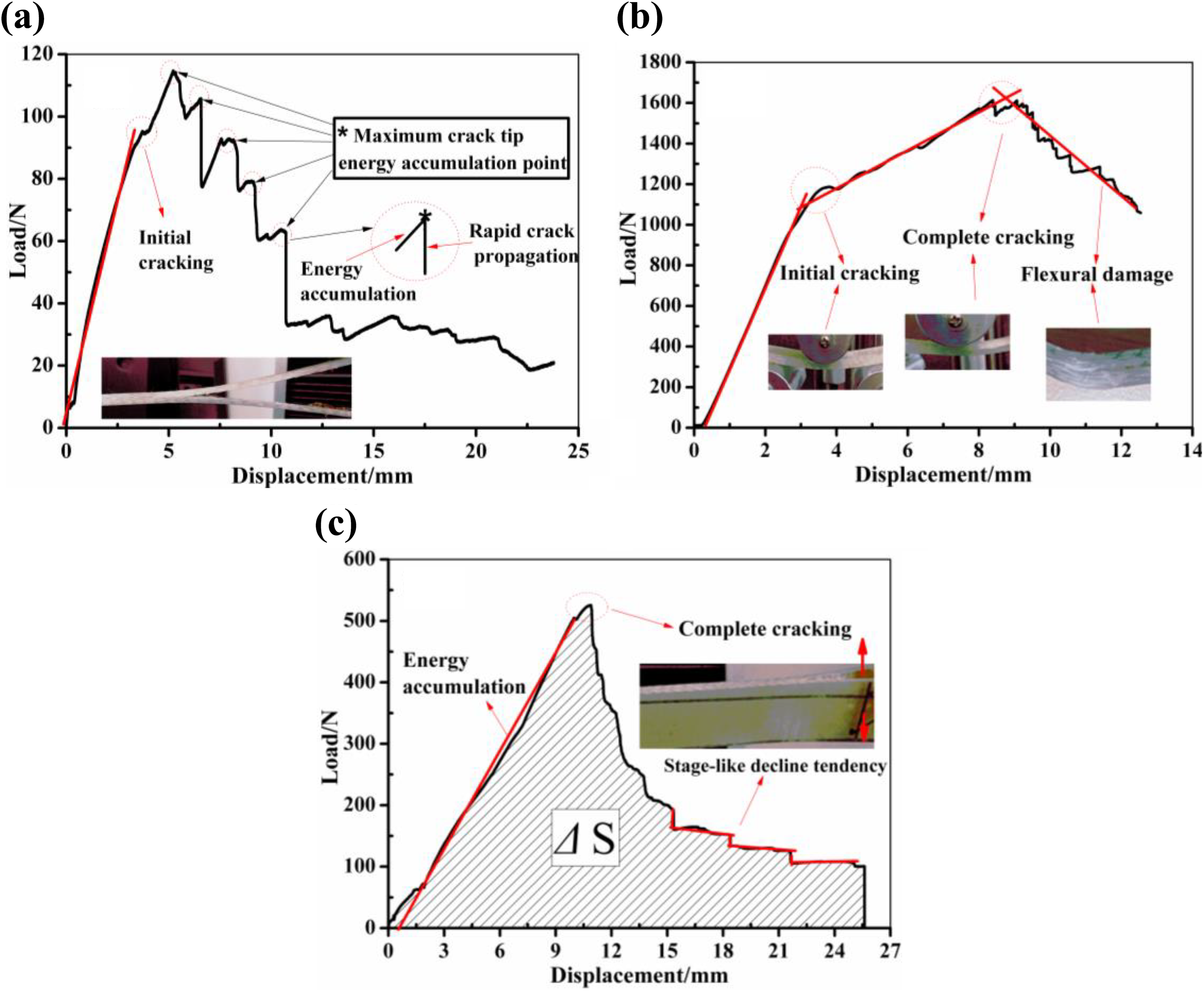
Load–displacement curves of WGF/Epoxy composites in (a) mode-I, (b) mode-II and (c) mode-III fracture toughness testing. WGF/Epoxy: woven glass fibre–reinforced epoxy.
Fracture toughness parameters of WGF/Epoxy calculated from experimental tests.

WGF/Epoxy: woven glass fibre–reinforced epoxy.


In these equations,
Load–displacement results of bolted joints with different outer plates
The flexural load versus relative displacement curves of the four specimens with 10-bolt double-lap joint configuration are compared in Figure 7. As can be seen, all the flexural load–displacement curves of the four specimens can be subdivided into five stages. Plastic-like nonlinear behaviour was observed for all the joint specimens. These responses indicate the considerable damage tolerance demonstrated by the designed joints. Therefore, the joint scheme can be considered as a good candidate for high energy absorption structure in ship engineering, and they also have the potential to be used in loading scenarios involving impact, shock and blast. Taking Figure 7(a) as an example, the flexural load increases linearly in the first stage (AB). There was no damage occurred in the bolted specimen due to the pretightening force applied to the bolts by the torque. In this stage, all the 10 bolts gradually slip into a bearing region around the holes in the composite laminates. However, the shear stress direction in the upper and bottom surface is inverse since the load transfer direction on both sides of the specimen is different. The load–displacement curve was linear as the load increased from 400 N to 2500 N, corresponding to a relative displacement of 0.02–8.45 mm. A nonlinear behaviour of the load–displacement curve was shown in stage BC, corresponding to relative displacements from 8.45 mm to 22.18 mm. The flexural load increases from 2500 N to 3779 N, which is the ultimate load of the specimen in bending test. Tensile in the bottom outer plate is the main load mode that bears the external flexural load. A platform appears in the figure in stage CD, and the displacement in this stage increases from 22.18 mm to 40 mm with the load kept at the same level. This might be due to the development of bearing failure around the holes and it further absorbs the flexural load energy during the test. The final stages (DE and EF) were the load reduction and sharp failure that occurred after exceeding the failure strength of the specimens. Similarly, the other three load–displacement curves have the same tendency. However, the load–displacement curve in [G3/C3/G12/C3/G3] specimens in Figure 7(c) exhibited a fast decline in stage CD, which was mainly due to the sharp shear damage on the upper surface in the specimens in the bending test. All the load–displacement curve characteristic of the specimens shows the progressive damage and failure response of the joints. Figure 8 compares the failure load and the load capacity of the four specimens obtained in the flexural tests. As clearly seen in Figure 8(a), the ultimate load of bolted composite joints with six layers of woven glass fabric layers as outer plates is the maximum among the four researched specimens, while that of the specimens with pure carbon fabric cloth as the outer layer is the smallest. Flexural failure load of bolted specimens with woven glass and carbon hybrid composites as outer layers is between [G6/G12/G6] and [C6/G12/C6] specimens. The load capacity of the four bolted composite specimens was calculated by ultimate load divided by the total specimen mass listed in Table 1. It can be found in Figure 8(b) that the load capacity follows the same tendency as the ultimate load. However, the bolted specimens with woven carbon fabric layer as outer contact layer in the flexural test have the same load capacity with the value of 3.89 N/g.
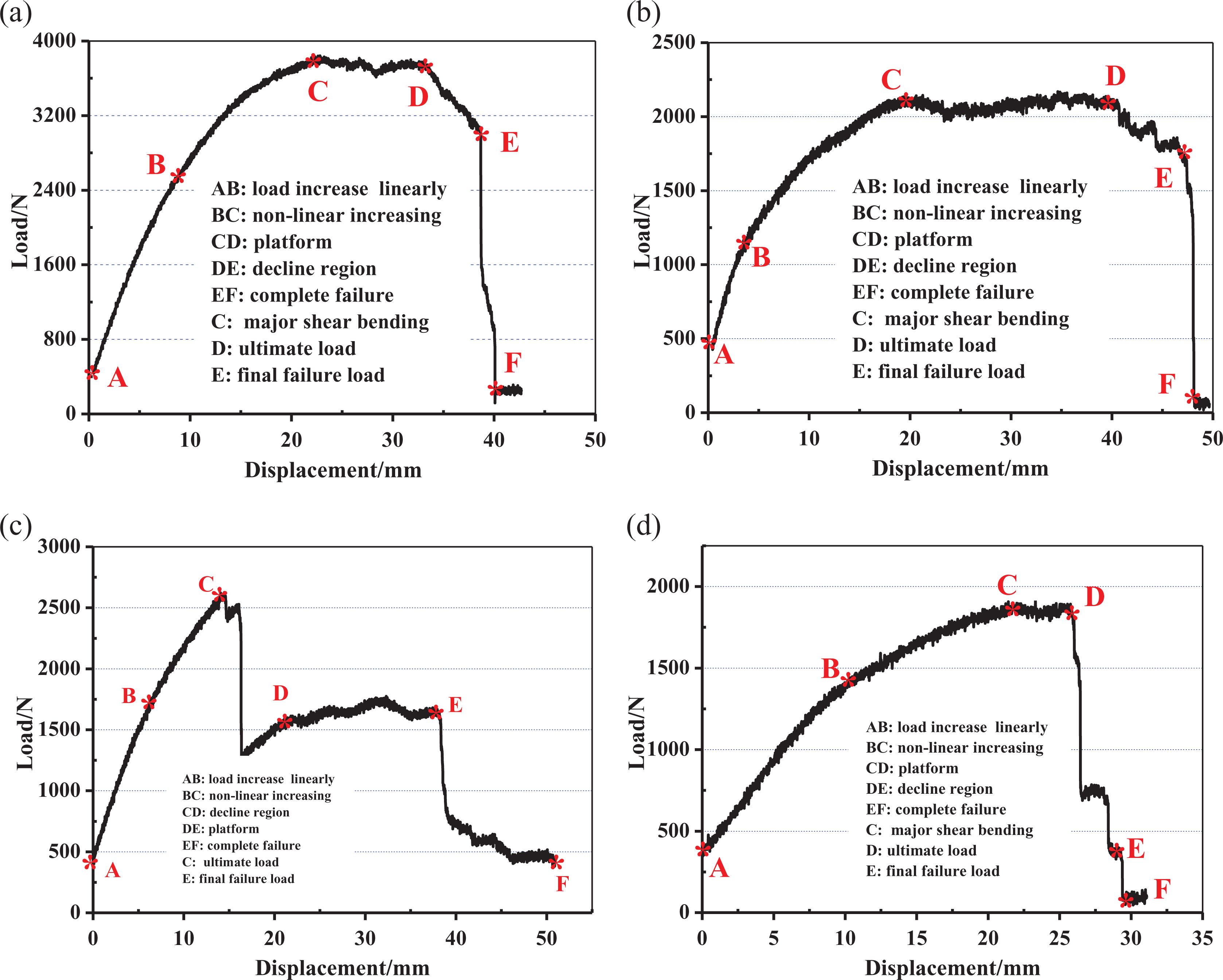
Typical load–displacement curve of different specimens in a three-point-bending test. (a) [G6/G12/G6], (b) [C3/G3/G12/G3/C3], (c) [G3/C3/G12/C3/G3] and (d) [C6/G12/C6].

Comparison of ultimate load and load capacity of various bolted composite joints in three-point-bending tests. (a) ultimate load and (b) load capacity.
Damage morphology in the joints after flexural test
For a composite laminate panel in the bending test, fibres in the contact side carry most of the compressive load while those in the bottom side carry a tensile load. In terms of hybrid composite laminates under three-point bending tests, it is known that the flexural strength of woven carbon fibre-reinforced polymer matrix composites can be improved by replacing carbon fibre at the compressive side with higher compressive strength glass fibres. Conversely, the flexural strength of glass fibre–reinforced composites can be improved through the addition of carbon fibres on the tensile side. The positive hybrid effect mainly depends on the effect of fibre volume fraction and carbon/glass fibre hybrid ratio. 23 In the case of the designed composite joints studied in this work, it can found that bolted composite joints with glass/carbon fabric panel as outer plates have positive hybrid effect comprised with pure carbon outer plates. It also can be found that the stacking sequence in outer plates with woven glass fabric cloth as contact surface has better mechanical performance mainly due to the excellent ductility of glass fibre. The strength of a composite joint is dependent on the failure mode. Microscopic damage patterns of glass and carbon fibres in the hybrid composites are shown in Figure 9. As can be seen, the failure modes in the specimen are generally composed of fibre tensile breaking on the lower surface, compress damage on the upper surface and/or debonding under shear stress inner the composites specimens. Fibre pull-out and debonding are the fundamental damage patterns under flexural load that affect the overall mechanical performance of composites significantly. The fracture in carbon fabric in hybrid outer plates is more flat than that of glass fabrics, which confirmed the brittle nature of carbon fibres. The macroscopic failure modes of the four different bolted laminated composite joints subjected to bending are shown in Figure 10. In the figure, failure occurred on compressive side of [C6/G12/C6] and [G6/G12/G6] bolted joints specimen is the most common failure mode that comprises fibre microbuckling and kinking. This results in a ‘load plateau’ in the load–displacement response, which suggests that kinking in bolted joints is a progressive failure mode. However, in [G3/C3/G12/C3/G3] and [C3/G3/G12/G3/C3], delamination between woven glass and carbon layers in the outer plate in the joint is clearly seen. In bending test, the compress stress in the upper hybrid panel was supported by the shear load from the 10 used bolts. This stress firstly causes initiated cracks in matrix in hybrid composite laminates. The further development of matrix cracking at the fibre tow causes small delaminate in contact region, and then, the cracks propagate as large delamination in the composite panel under compressive load. Due to the higher failure strain of glass fabrics, woven glass fabrics have higher breaking extensibility than carbon fabrics in hybrid outer laminates. Mainly due to the mismatch of deformation in glass and carbon fabrics in the test, opportunity of delamination between glass layers and carbon layers in hybrid composites under shear load improved. Delamination could absorb some of the damage energy, and this factor enhances the ultimate load of hybrid composites in [G3/C3/G12/C3/G3]. The final load drop is attributed to fibre breakage on the tensile side for all the joints under bending load, and this leads to the large fibre pull-out region in Figure 10.
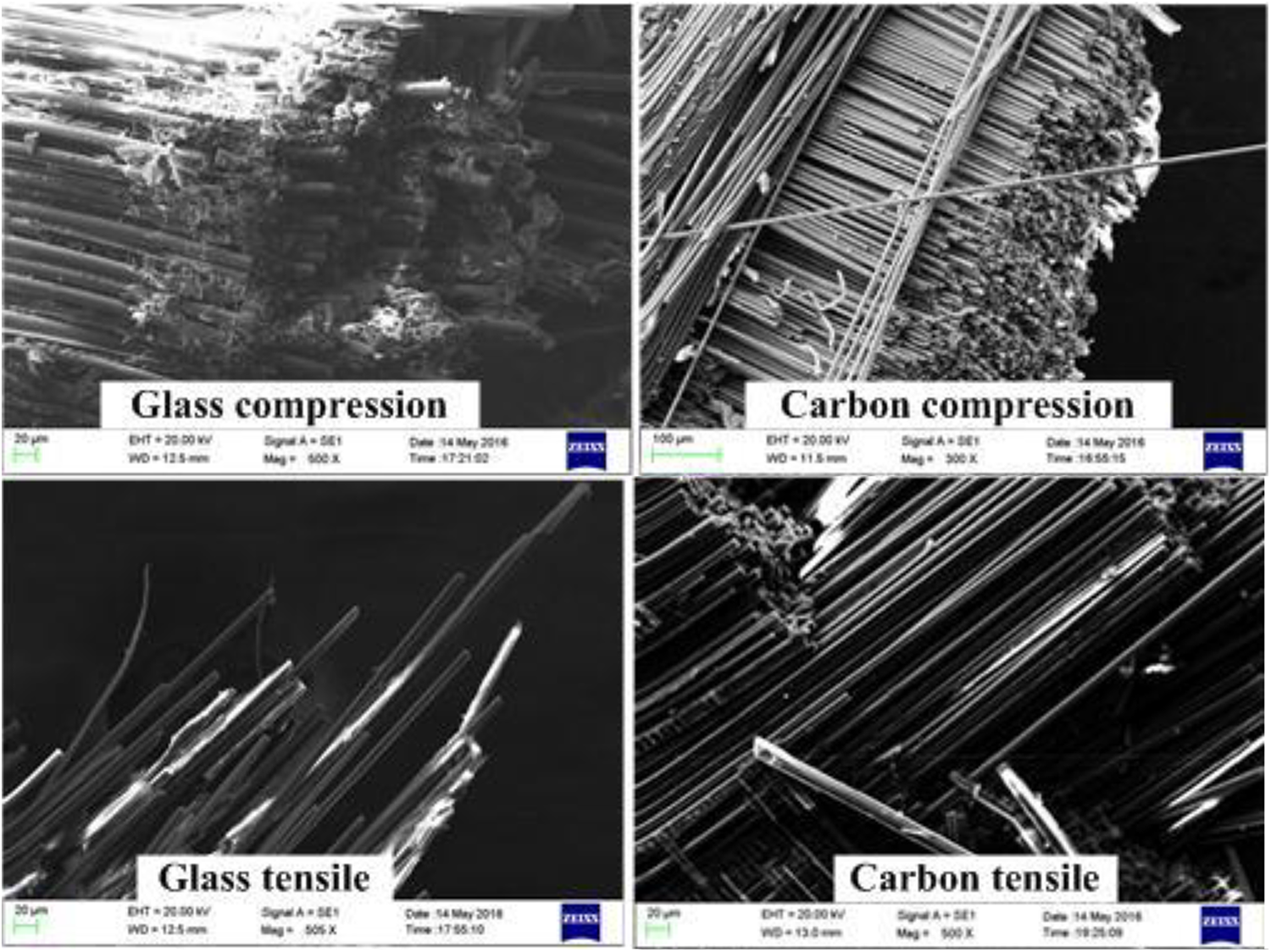
Micro topography of glass and carbon fibres on the tensile and compressive sides.

Final damage mode of specimens in a bending test.
Conclusion
This article investigated the performance of a designed double-lap bolted composite joint with different outer plates subjected to bending load. From the experimental investigation, we obtained the fundamental mechanical parameters of the prepared woven glass fabric–reinforced epoxy composite materials made by VARI processing. The interlaminar performance of the prepared WGF/Epoxy composites was evaluated, and unstable crack propagation characteristics in the test were found, which were indicated by the stage-like load–displacement curves. Bolted joints with [G6/G12/G6] and [C6/G12/C6] as outer plates had maximum and minimum flexural strengths, while the strength of joints with hybrid composite panel as outer plates was in between them. Hybrid composites with structural style of [G3/C3/G12/C3/G3] had larger flexural strength than [C3/G3/G12/G3/C3], which was mainly due to the protection effect of glass fabrics caused by their higher failure strain. Progressive damage characteristics of the bolted joints in three-point-bending tests were found in the load–displacement curves. Fibre compressive damage on the upper side and tensile damage on the bottom side of the specimen were the main damage modes in the tests. By SEM observation, it was found that the fracture of carbon was smoother than that of the glass fabrics on both sides of the joints.
Footnotes
Acknowledgements
The authors would like to thank the National Natural Science Foundation of China and the Fundamental Research Funds for the Central Universities.
Declaration of conflicting interests
The author(s) declared no potential conflicts of interest with respect to the research, authorship, and/or publication of this article.
Funding
The author(s) disclosed receipt of the following financial support for the research, authorship, and/or publication of this article: This work was supported by the National Natural Science Foundation of China (No. 11702097) and the Fundamental Research Funds for the Central Universities (No. 222201714015).