



Abstract
This article investigates the safety control problem of intelligent networked vehicle and utilizes the sliding-mode control to solve the system with time delay, system disturbance, and parameter uncertainty. First, the modeling of automobile system is introduced. What’s more, time delay, parameter uncertainty, disturbance, and attack are added to the original model. Then, designed an integral sliding-mode surface and given the sufficient conditions for system stability using linear matrix inequalities. Furthermore, the controller is designed according to the slide approach rate, and it is proved that the designed controller can make the system state reach the sliding surface in finite time. Finally, the simulation is used to verify the effectiveness of the arithmetic.
Introduction
The network control system refers to a real-time network closed-loop control system in which the equipment collects data through on-site data collectors such as sensors, and then transmits data through the network system to share information resources among users, and finally realizes collaborative control through the controller.1–3 With the development of computer networks, networked control systems have aroused the interest of many researchers and have been widely used in many fields, such as environmental science, 4 power industry, 5 computer science, 6 aerospace 7 and weapons industry 8 . Intelligent connected vehicle is a typical network control system. In recent years, people’s traffic demand has been increasing. Intelligent connected vehicle has become a hot research topic because it can reduce energy consumption, relieve traffic pressure, and reduce traffic accidents (see Wang et al. 9 and Yan et al. 10 and the references therein). The main target of intelligent networked vehicle control is to make the vehicles drive safely at a set desired distance and speed. 11 In the actual situation, the system will inevitably encounter interference, even malicious attacks by hackers, and so on. The actual system also has time delays due to network transmission, and the uncertainty of vehicle parameters caused by use in different environments. These factors will reduce system performance and even lead to serious accidents, causing damage to human safety and property. Therefore, how to design a control strategy so that the system can still maintain normal working when suffering from the above situation to avoid accidents has become a problem which should be solved instantly.
So as to suppressing system disturbances, many studies have done many investigations in this area.12–14 Li et al. 15 studied the external disturbances and network-induced disturbances of vehicles’ follow-up control and proposed a discrete-time sliding-mode control arithmetic which can be adaptive. For the overhead crane systems, Wu et al. 16 proposed a sliding-mode controller and an observer of nonlinear perturbance for the adjustment and perturbation reckoning. In Li et al., 17 for the purpose of solving the position interference robust control problem of permanent magnet synchronous motor, a robust control method is proposed for solving the tracking control problem of servo system. Although the above references have achieved good results in suppressing disturbances, they ignore the possible disturbances and even hacking attacks between the controller and the actuator, which makes the designed controller unable to deal with attacks.
Hacker attack is a more important issue. Attackers often maliciously undermine system stability to achieve their illegal purposes. Such interference factors often cause greater damage to the intelligent connected vehicle system. Common network attacks are denial of service attacks, 18 deception attacks, 19 and replay attacks. 20 Deception attack is also called false data injection attack. Attackers use the state information or measurement data of the system to attack the communication information between the controller and the actuator. Such attacks can bypass the attack detection mechanism to attack the physical system, so that it is difficult to be detected. In order to solve the damage of hacker attacks to the system, Zhao et al. 21 studied the design of false data injection attacks and how to detect it in cyber-physical systems, and a design scheme is proposed using subspace technology for fake data injection attacks in the systems. For solving the distributed attack and recovery in vehicle platoon control systems, Mousavinejad et al. 22 developed a distributed attack discovery algorithm and introduced two restoration mechanisms based on computational prediction ellipsoid sets and estimation ellipsoid sets. In Liu et al., 23 dynamic event-triggered control of attacked network systems is studied, and a dynamic event-triggered mechanism for hybrid systems is proposed. However, parameter uncertainty and time delay are also problems in practical systems. In the above references, the recovery of systems under attack is discussed in detail, but the effects of system time delay and parameter uncertainty are ignored.
Aiming at the time lag resulted by network transmission and parameter uncertainty engendered by system aging, Xu et al. 24 considered isomeric vehicles on complex road conditions, aerodynamic resistance and network communication lag and proposed an integrated platoon control framework. Han et al. 25 designed a robust forecast controller with tamper-resistance function for the problems of time delay, disturbance, and parameter uncertainty faced by supercavitating vehicles. For linear discrete time-delay systems, Ghrab et al. 26 considered the effects of uncertainties on state and delay state vectors and proposed a controller based on sliding-mode algorithm. The conditions of asymptotic stability are derived, and a new Discrete-Time Sliding Mode Control (DT-SMC) law is obtained. However, the system including parameter uncertainty, time delay, disturbance, and attack has not been entirely studied. It gives inspiration for the research of this article.
In this article, we mainly study the safety control problem of intelligent connected vehicles driving on horizontal roads under parameter uncertainty, time delay, disturbance, and false data injection attacks. The primary work of this article is as follows:
An intelligent networked vehicle system model is established, and added time delay, parameter uncertainty, disturbance, and false data injection attack to the original model.
For the purpose of making the system state follow the predetermined trajectory, an integral sliding-mode surface is proposed. The stability condition of sliding-mode dynamic is given by combining the linear matrix inequality theory with the Lyapunov theory.
In order to make the system state get to the sliding-mode surface and remain stable under the conditions of time delay, parameter uncertainty, attack, and disturbance, a sliding-mode controller is proposed using approach rate.
The structure of this article is as follows. Section “Problem formulation” describes the intelligent connected vehicle system. In section “Design and analysis of sliding-mode function,” a sliding surface is designed, then the stability of the sliding-mode dynamics is proved, and the stability conditions of the system are given. In section “Design of controller and stability analysis,” a sliding-mode controller is designed and the accessibility of the sliding-mode surface is proved. In section “Illustrative example,” the feasibility of the designed controller is verified by simulation.
Notations
“*” denotes the symmetric term in symmetric entries, E denotes the unit matrix of appropriate dimension,
Problem formulation
Consider a vehicle running on a horizontal road. We can obtain the desired acceleration, velocity, and position through the network. The vehicle is equipped with sensors to detect the positional relationship with the previous vehicle. Let

where q is the engine input for the vehicle, and

where q is the engine input of the vehicle;
To facilitate the analysis, the following controller is set by feedback linearization

Substituting equation (3) into the third formula in equation (1) gives

Define the state vector as

where

Define the expected distance of the vehicle as
Using coordinate transformation to move the expected state of the vehicle to the zero point, we get

where
Generally speaking, considering the application of the vehicle in the actual system, first, because of the different scenarios when the vehicle system is used, resulting in different temperatures, combined with the service life of the system components aging, system parameters will change, parametric uncertainty should be added to the model. Second, the communication between vehicles has time difference, which is system time delay. Finally, adding system disturbance makes the model closer to the actual system. After adding the above factors, the system is as follows

where
Assumption 1.

where

Assumption 2.

where
Fake data injection attack is a common attack method. Shown in Figure 1, the attacker uses the system state information or measurement data to attack the communication channel between the controller and the actuator. Such attacks can reduce the system performance or even destroy the normal operation of the entire system. And it is difficult to be detected directly. The fake data injection attack model is modeled as follows 28

where

Control system under false data injection attack.
Assumption 3.
Assumption 4.
where
Under a fake data injection attack, the control signal accepted by the actuator will be expressed as

Substitute the actual control signal equation (12) into the system state equation to get

Design and analysis of sliding-mode function
In this section, first, designed an integral sliding-mode surface in order to make the system state follow the predetermined trajectory. Then, analyzed the stability of the sliding-mode dynamic, and the conditions of system stability are given.
Design of sliding-mode surface
In this section, an integral sliding-mode surface is designed as following

where L represents the parameter matrix to be designed, which will be solved in the following theorem. Matrix

Furthermore, let

Substitute equation (16) into the system state equation (13), the following sliding-mode dynamic can be obtained by

where
Stability analysis
In this section, we analyze the stability of the sliding-mode dynamic equation (17) and derive the sufficient conditions for the stochastic stability. In order to solve the stability problem, the definition of stability is given as follows.
Definition. There is
1. When disturb

2. For a non-zero perturbation

where
Next, the lemma is given to facilitate the solution of parameter uncertainty
Lemma. If

The stability of sliding-mode dynamics is proved as follows.
Theorem 1. For the system (17), when disturbance

Then, the sliding-mode dynamic equation (17) is stable.
Proof. Select the Lyapunov function as

Derivation along the state trajectory of sliding-mode dynamic equation (17)

Using Assumption 2, that is, equation (10), we get

Let

According to inequality equation (21), it can be further obtained

where

According to Dynkin’s formula, it is obtained that
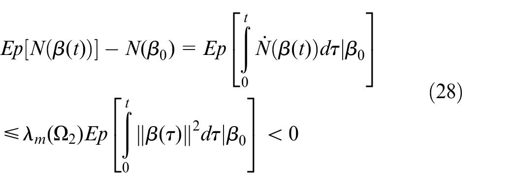
Using

Let

According to the definition, when the disturbance
Theorem 2. For automatic driving system, the sliding-mode surface is determined by equation (14), if there is a positive definite matrix J, scalar

where

Proof. Select the function as following

According to Theorem 1, it can be derived that
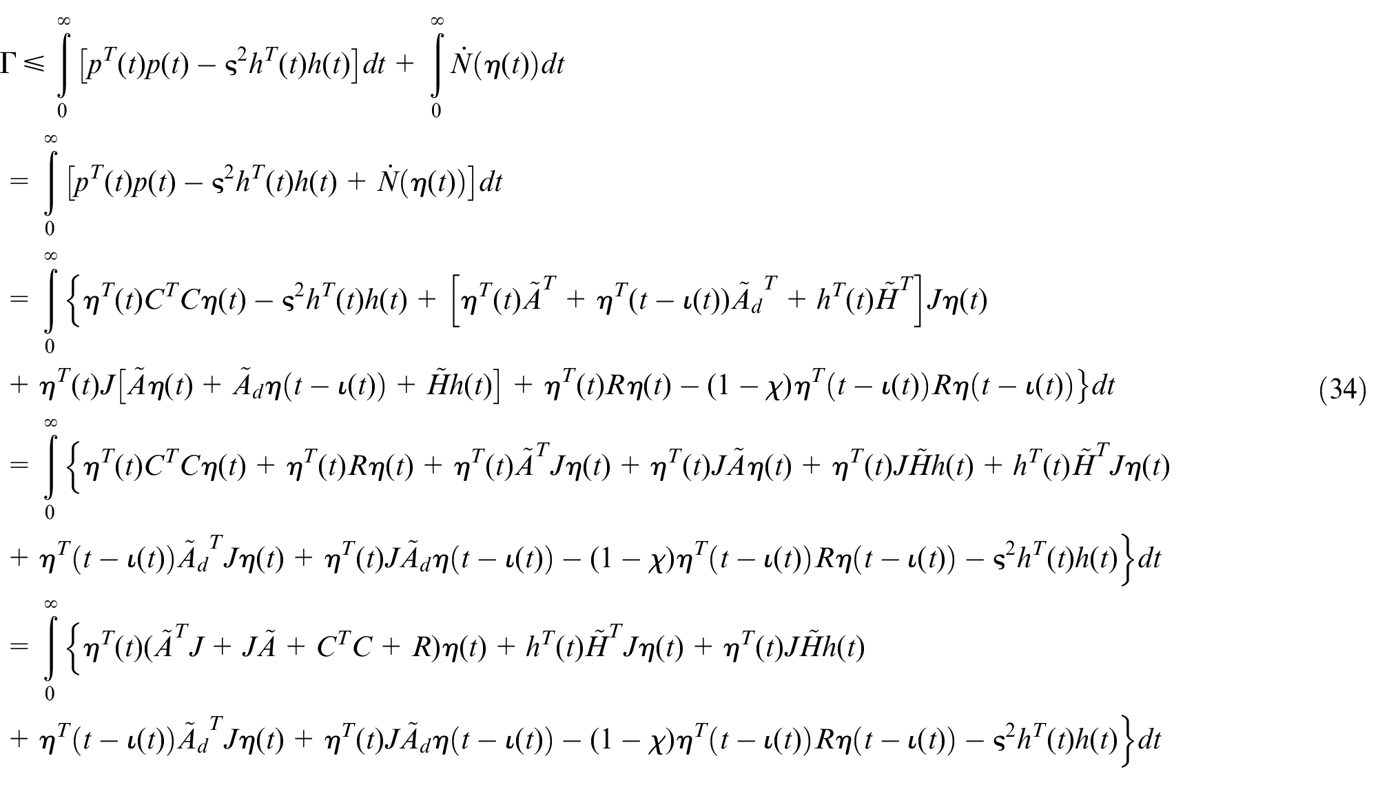
Let

where
Let

Combining equations (35) and (36) and using Shur’s complement theorem, we get

where

where
Further simplification yields
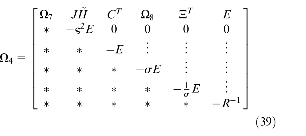
where
Then pre- and post-multiplying

From equation (31), it can be known that equation (40) is less than 0. According to Theorem 2, it can be deduced that the system is stable.
This completes the proof.
Design of controller and stability analysis
In this section, a sliding-mode controller is designed and then it is proved that the system state can close to the sliding-mode surface in a certain time by the designed controller. The controller is designed as follows.
In the actual vehicle system, the state value is limited. For the purpose of facilitating the processing of the time lag term, the assumptions are made as following.
Assumption 5. Suppose system state is bounded and satisfies

Remark 1. For the automotive system, the system state
Select the constant velocity approach rate

where
It is demonstrated below that the designed controller can satisfy the accessibility of the sliding-mode surface.
Theorem 3. For the automobile system, when the sliding-mode function is determined by equation (11) and
Proof. Choose the Lyapunov function as

Taking the derivative of

According to Assumptions 1 and 2, we can get
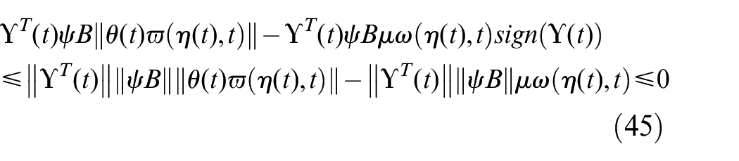
Combined Assumption 5 and substituting
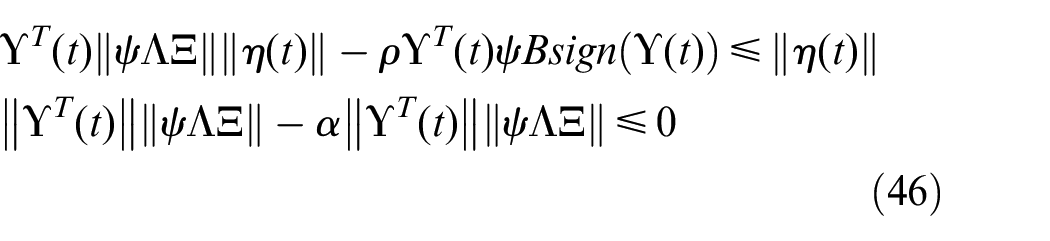
Similarly, according to Assumption 5, we can get

Furthermore, it can be deduced that

According to the Lyapunov stability condition, it can be obtained from
Illustrative example
For the purpose of proving the sliding mode in this article when there are parameter uncertainties, time delays, system disturbances, and false data injection attacks in the automotive system, a simulation example is designed to proving the feasibility of controller in this section.
The parameter settings are
Through Theorem 2, matrix J and sliding-mode parameter matrix L can be solved as

Figure 2 displays the trajectory of the sliding surface. It can be known that the sliding surface converges to 0 in about 2.6 s and the convergence of the sliding surface is narrow, which proves that the dynamic performance of the sliding surface is good. Figure 3 displays the trajectory of the acceleration error. It can be known that the acceleration error is stabilized at 0 in about 3 s, and the small chattering is the normal phenomenon of the sliding-mode controller, which is within the acceptable range. Figure 4 displays the trajectory of the position error, which shows that the position error converges to 0 in about 3 s. Figure 5 shows the trajectory of velocity error, which tends to be stable in about 3 s. Figure 6 displays the comparison between the actual acceleration and the expected acceleration. It can be known that in addition to a certain error at the beginning, the tracking trajectory almost coincides with the expected trajectory. Figure 7 shows the comparison between the actual position and the expected position. It can be known that the position tracking effect is good. Figure 8 displays the comparison between the velocity trajectory and the expected velocity trajectory, and it can be known that the tracking effect is also good. Figure 9 displays the trajectory of the control input, which is stable in about 3 s, and then fluctuated around 0. The simulation results show that under the influence of initial error and parameter uncertainty, time delay, false data injection attack, and disturbance in the vehicle system, the designed controller can still guarantee the convergence of the system state in finite time and the error is small.

Sliding-mode surface.

Acceleration error.

Position error.

Velocity error.

System output acceleration.

System output position.

System output velocity.

Controller input.
Furthermore, in order to demonstrate the effectiveness of the designed controller, the larger parameter uncertainty is used in the simulation. The specific parameters are

Acceleration error.

Velocity error.

Position error.
Conclusion
In this article, we studied the safety control problem of intelligent connected vehicles. In which, designed an integral sliding surface and proposed a sliding-mode control strategy. First, considering a vehicle running on a horizontal road, a vehicle model with disturbance, attack, time delay, and parameter uncertainty is established. Second, for the purpose to make the system state slide according to the predetermined trajectory, we proposed an integral sliding surface. Then, we proved the stability of the sliding-mode dynamics, and the stability conditions of the system are given using the linear matrix inequality and Lyapunov theorem. Third, we derived a sliding-mode controller, and then it is proved that the system state can reach the sliding surface by the proposed sliding-mode controller within the certain time limit. Finally, we used a simulation to verify the correctness of the sliding-mode controller.
Footnotes
Declaration of conflicting interests
The author(s) declared no potential conflicts of interest with respect to the research, authorship, and/or publication of this article.
Funding
The author(s) disclosed receipt of the following financial support for the research, authorship, and/or publication of this article: This work was supported by the Key Research and Development Program of Sichuan Province under grant (2023YFG0185), the Natural Science Foundation of Sichuan under grant (2022NSFSC0868 and 2022NSFSC0902), and the Medico-Engineering Cooperation Funds from University of Electronic Science and Technology of China (ZYGX2021YGLH223).
