
Abstract
In this article, a preliminary design framework containing a detailed design methodology is developed for modern low emissions aero combustors. The inter-related design elements involving flow distribution, combustor sizing, heat transfer and cooling, emission and performance are coupled in the design process. The physics-based and numerical methods are provided in detail, in addition to empirical or semi-empirical methods. Feasibility assessment on the developed work is presented via case studies. The proposed combustor sizing methodology produces feasible combustor dimensions against the public-domain low emissions combustors. The results produced by the physics-based method show a reasonable agreement with experimental data to represent NOx emissions at key engine power conditions. The developed emission prediction method shows the potential to assess current and future technologies. A two-dimensional global prediction on liner wall temperature distribution for different cooling systems is reasonably captured by the developed finite difference method. It can be of use in the rapid identification of design solutions and initiating the optimisation of the design variables. The altitude relight efficiency predicted shows that the method could be used to provide an indicative assessment of combustor altitude relight capability at the preliminary design phase. The methodology is applied and shows that it enables the automatic design process for the development of a conceptual lean staged low emissions combustor. The design evaluation is then performed. A sensitivity analysis is carried out to assess the design uncertainties. The optimisation of the air distribution and cooling geometrical parameters addresses the trade-off between the NOx emissions and liner wall cooling, which demonstrates that the developed work has potential to identify and solve the design challenges at the early stages of the design process.
Introduction
Pollutant emissions from aircraft in the vicinity of airports and at altitude are of great public concern due to their impact on the environment and human health. The legislation aimed at limiting aircraft emissions has become more stringent over the past few decades. This has resulted in an urgent need to develop low emissions combustors to meet legislative requirements and reduce the impact of civil aviation on the environment. 1 Design of a low emissions combustor is a challenging task as it demands knowledge of complex three-dimensional flow, liquid droplet evaporation, chemical kinetics, heat and mass transfer, etc. The research mainly focuses on the experimental and numerical study to investigate the detailed physics in the combustion chamber with very limited study in the public domain focusing on preliminary design framework development. The high cost of rig testing and increased complexity of numerical simulations limit their use in the conceptualisation of design. Preliminary design tools are of great importance as they enable novel design solutions to be explored in a relatively shorter timeframe.
Such design tools have been developed by some of the engine original equipment manufacturers to assist the combustor development.2,3However, there are limited design approaches in the public domain. Stuttaford and Rubini developed a preliminary design tool using a network approach. 4 The approach was used to model the combustor mass flow splits and pressure drop using a pressure-correction methodology. It is also capable of modelling heat loss using conjugate heat transfer models. The detailed combustor design and sizing procedures were however not extensively investigated. Mohammad and Jeng developed a design tool for single annular combustors (SACs). 5 The design and combustor sizing procedures are empirical/semi-empirical based. Khandelwal et al. conducted the design and performance analysis for staged combustors. 6 The methodology developed follows the conventional method similar to Mohammad and Jeng’s approach. More recently, Mark and Selwyn performed design and analysis on a low bypass turbofan combustor. 7 The dimensions of the designed combustor were determined based on the empirical formulas. Li et al. developed design methods for lean direct injection combustors. 8 The work mainly focused on aerodynamic design. Roshan et al. provided design philosophy for a laboratory-scale combustor where various empirical relations were adopted in the design process. 9
The contributions of the present research compared to the previous studies are: (1) a more detailed and compressive design approach for modern low emissions combustors is developed. In particular, the methods for determining air and fuel distribution for staged combustors, fuel–air mixer, cooling system, and other key combustor components are provided in details. (2) Previous approaches focus specifically on certain design elements and design procedures are applied sequentially in the design process. Interactions of different design elements in the preliminary design phase are not extensively studied. In current work, the inter-related design elements involving aerodynamic sizing, heat transfer and cooling, emission and performance are coupled in the design process. (3) The previous studies are generally related to conventional design rules and mainly empirical-based. In this study, multiple approaches including physics-based and numerical methods are provided in detail, in addition to empirical/semi-empirical methods. (4) Limited studies combine preliminary design with optimisation to investigate the trade-offs between conflicting performance requirements, this will be considered in the current design framework.
Methodology development is presented in the following section. The following subsection provides an overview of the whole design framework. The coupled design elements and their interactions are presented in next subsection. Sections ‘Flow distribution’ to ‘Performance’ show detailed methods. It comprises flow distribution, combustor sizing, emission prediction, heat transfer and cooling, and performance analysis. The developed flow distribution programme produces air and fuel data into different combustor sections. The combustor sizing results in the combustor casing, liner, diffuser, fuel-air mixer, and cooling system design. The proposed heat transfer and cooling methodology estimate the airflow required for the liner cooling. It is also capable of providing a two-dimensional temperature distribution along the liner wall. The developed emission methodology provides an assessment of key engine emission index (i.e., NOx) for different combustor technologies at key engine power conditions. For performance evaluation, the combustion efficiency levels are assessed. In the third section, the feasibility assessment on each design approach is presented via case studies. An overview of each design approach is provided. The developed methodology is then applied and presented in fourth section. A conceptual lean staged combustor is designed for a smaller turbofan engine. The overall performance of the designed combustor is predicted. In fifth section, a multi-objective optimisation is incorporated in the design framework. The work focuses on optimising airflow distribution and cooling geometrical parameters to address the trade-off between the NOx emissions and liner wall cooling.
Methodology development
Methodology overview
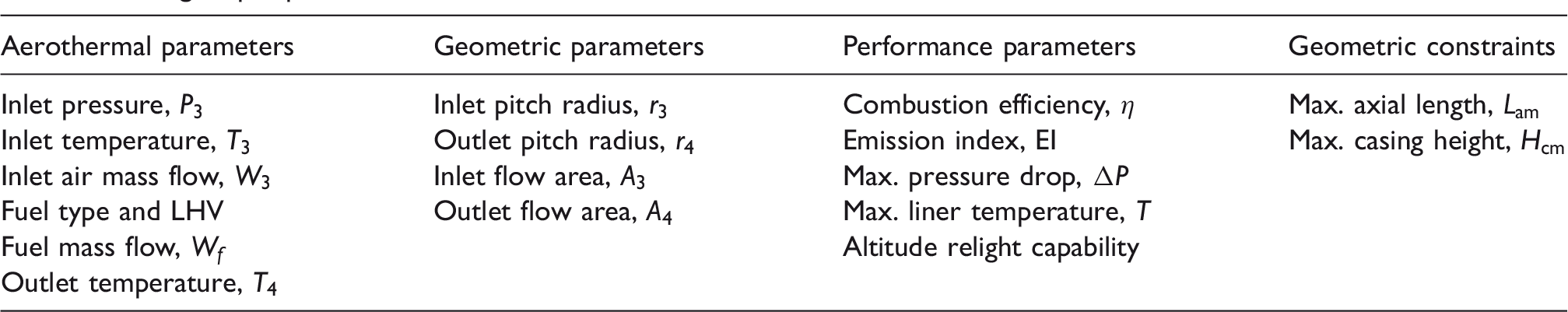
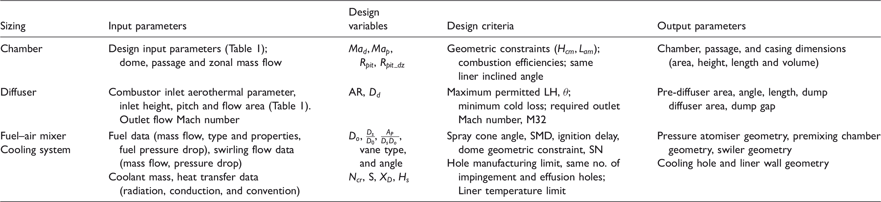
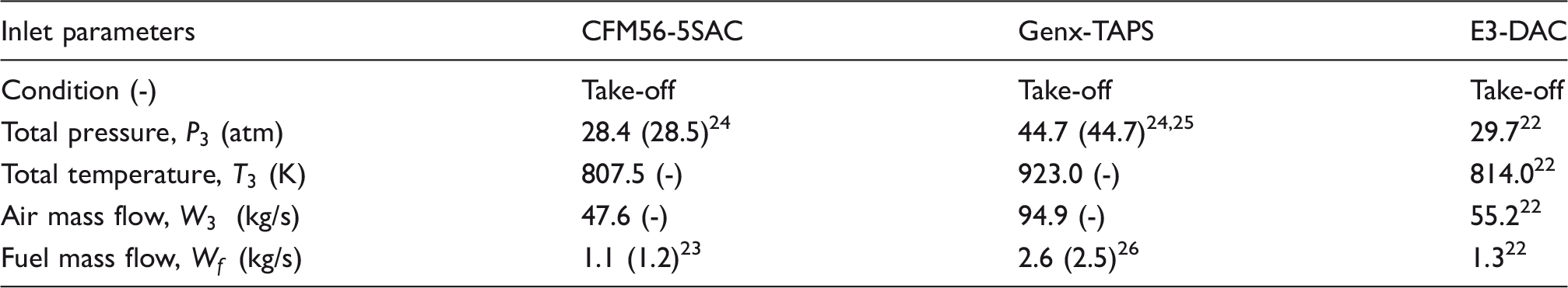
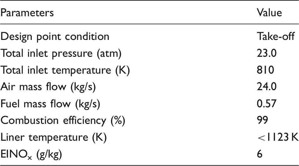
The global design process within the developed framework comprises a series of steps as indicated in Figure 1. Before starting the process, various design parameters are defined. As listed in Table 1, the design parameters include: (1) aerothermal parameters (i.e., combustor inlet/outlet pressure Preliminary design framework- global design process. Design input parameters.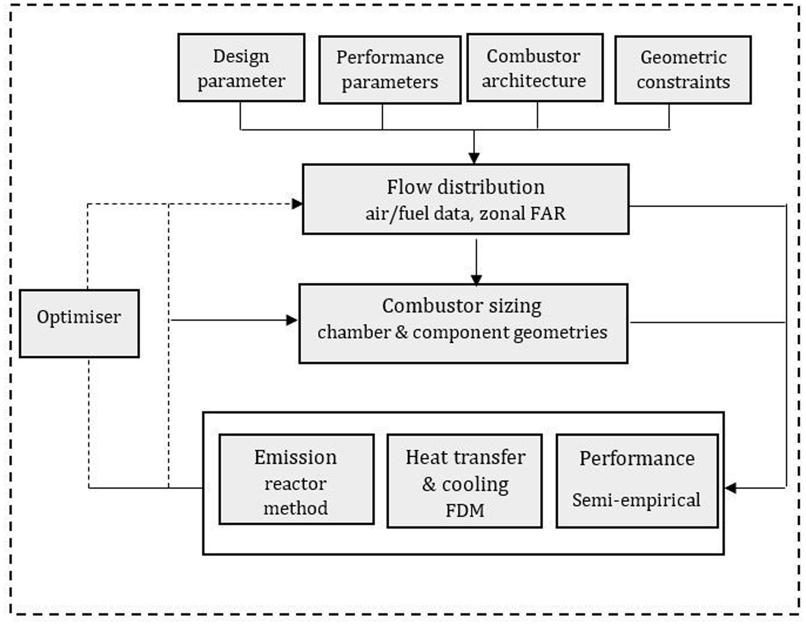
After initialisation, the process starts with flow distributions. The airflows through different combustor sections are initially estimated. Specifically, the air mass flows through combustor swirlers, different stages, dome, passage, and liner cooling flow are calculated. If staged combustors are designed, it allows the fuel schedule between the pilot and the main stage. With calculated air and fuel data, the combustor zonal fuel–air stoichiometric ratios can be defined.
Then, the design parameters and calculated flow data are transferred to the combustor sizing algorithm. A new combustion system design relies heavily on past experiences. It is still governed by correlations which could be very useful for combustor sizing. 10 Within the current sizing algorithm, the design variables are defined, and various sizing rules and semi-empirical correlations are incorporated. In particular, the detailed and new design rules were developed to determine the geometries of liner, diffuser, fuel–air mixer and cooling holes. Moreover, the algorithm also allows the customised semi-correlations to be incorporated into the framework to assist the designers according to their personal needs.
The defined aerothermal, flow distribution and combustor geometric data are then transferred to the developed emissions, heat transfer and performance algorithms where evaluation on the designed combustor is performed. For emission analysis, NOx is of high importance for the design of future aero-engine combustors since the legislative requirement becomes increasingly stringent. 1 The empirical correlations limit their use for the emission prediction since the coefficients in the parameters may not be valid for new combustors. Although higher-order numerical simulations would provide more accurate prediction, the calculations are not efficient for technology evaluations, particularly in the preliminary design phase. In the present work, the physics-based method is developed within the emission algorithm. The combustion chamber is divided into a number of zones based on the layout of the combustor and each zone is modelled as a combination of several stirred reactors. The approach reduces dependence on specific rig test information, and the modularity and extensibility enable the new technology to be evaluated rapidly. The method details are provided in ‘Chemical pollutants’ section. One-dimensional heat transfer analysis is usually performed to evaluate liner mean temperatures and estimate the cooling flow. However, the liner temperature distribution is of more interest because peak temperatures and temperature gradient are two crucial factors that affect liner integrity. The multi-dimensional analysis is considered in the current algorithm by approximating the liner temperature distribution using the finite difference method (FDM). ‘Heat transfer and cooling’ section provides the details. Safety is always the most important airworthiness criterion and there is no exception for low emissions combustors design. High combustion efficiency not only at design point but during altitude relight is required. A semi-empirical approach is proposed in the performance algorithm to evaluate altitude relight efficiency. The algorithms are interrelated, and a detailed description of the coupling process is presented in the following subsection.
The iterative design loop is then formed by changing the combustor geometric design variables and air/fuel data and checking whether the designed combustor meets the design targets. The iteration will continue until the design meets all the requirements. The process is experience-driven and is trial and error. A more effective way to attain the design goals is by using the optimisation technique to automate the design process. In this work, a genetic algorithm optimiser is also connected to the design framework. It is achieved by optimising the design variables to address the combustor trade-offs between the multi-design objectives.
Design element interaction
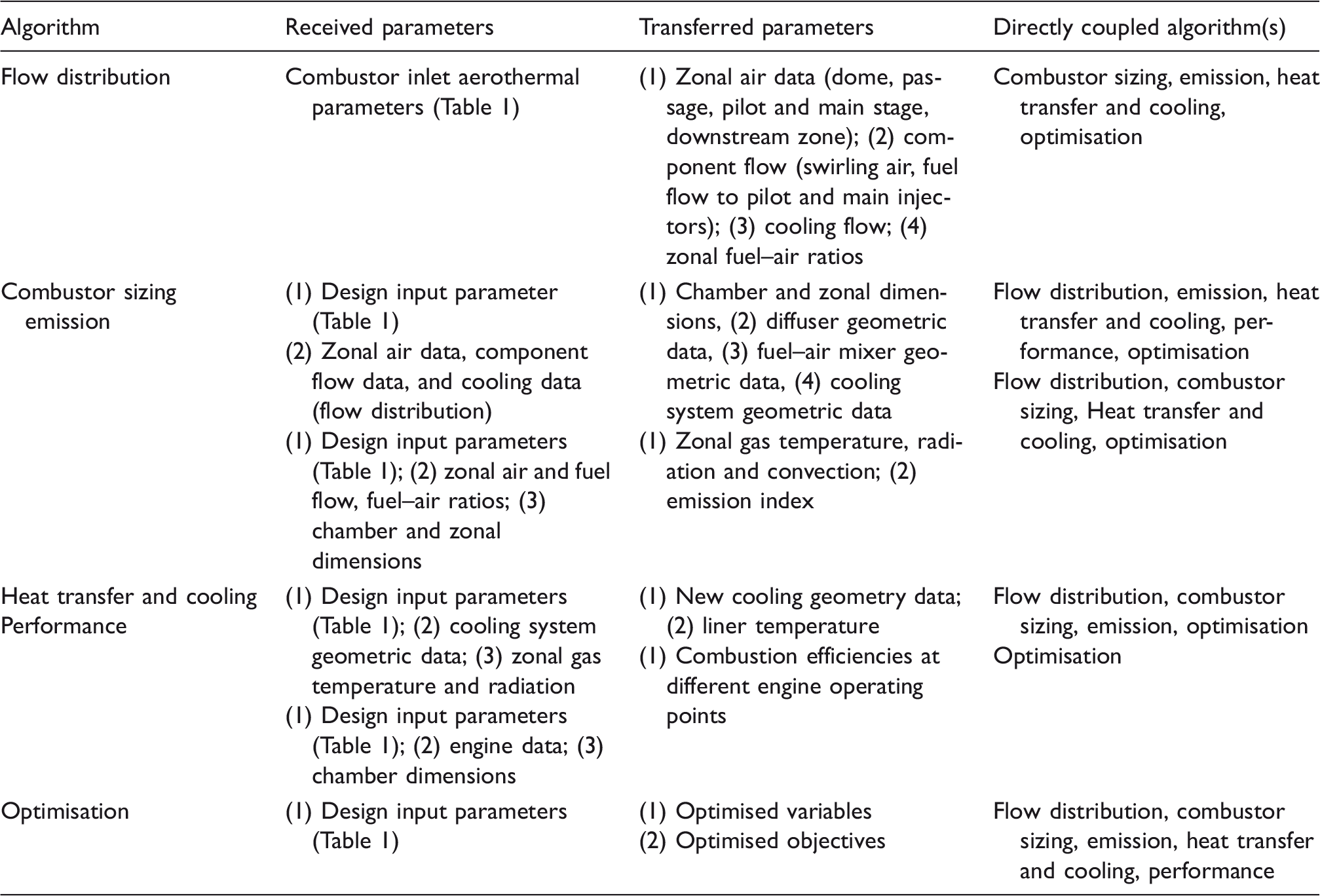
Instead of applying a sequential design procedure, the developed algorithms are coupled to enable a mutual communication process when conducting a design task. This allows the designers to rapidly explore the mutual impact relation between different design elements. Table 2summarises the interactions by listing the parameters where each algorithm receives from and transfer to other algorithms. For each algorithm, the directly coupled algorithms are also given.
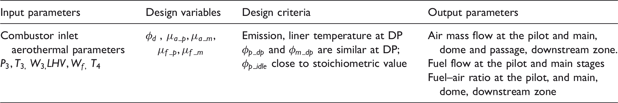
Flow distribution The combustor inlet aerothermal parameters (Table 1) are initially received by the algorithm. Within the algorithm, the air mass flow used for combustion and liner cooling is estimated. Meanwhile, the airflow through the different combustor sections components is determined. The fuel splits between the pilot and the main stage are also defined if a staged combustor is designed. The calculated air and fuel flow data are transferred to: (1) combustor sizing algorithm, the dimensions of swirlers, combustor cooling holes and liner zone (e.g. the pilot and main zone, dome and passage) can be defined with given air mass. The fuel flow is used to provide the fuel nozzle orifice dimensions. (2) Heat transfer and cooling algorithm, the initially estimated cooling flow will be used for liner heat transfer and temperature analysis. (3) Emission, the fuel and air mass, and the zonal fuel–air stoichiometry are transferred to the reactors in the emission algorithm. Within reactors, the reactant mixture quantity is defined. (4) Optimisation, the resulting flow parameters can be defined as variables to the combustor flow optimisation. Although the algorithm does not directly link with performance algorithm (i.e., combustion efficiency is evaluated based on the inlet parameters), the resulting liner dimensions based on flow distribution will be used for efficiency analysis. Combustor sizing The sizing programme receives the design parameters (Table 1) and mass flow data from the flow distribution algorithm. Within the programme, the dimensions of the combustion chamber and combustor components are generated. The determined geometrical values are coupled to: (1) heat transfer and cooling algorithm. Specifically, the liner cooling geometrical data provide the computational domain where the grids are generated for FDM analysis. (2) Emission, the produced overall and zonal chamber dimensions define the geometric boundary conditions for each reactor; in specific, the inlet and outlet areas, and reactor length. The defined reactors are then further connected to formulate the network. (3) Performance, since the semi-empirical approach is used to evaluate combustion efficiency levels, the calculated chamber dimension is an important parameter. (4) Optimisation, the identified geometrical design variables could be treated as ones used for multi-disciplinary optimisation. Emission The mass flow calculated from flow distribution model, and geometric parameters from combustor sizing model provide the basis for emission modelling. Within the algorithm, the chemical kinetics calculations inside the stirred reactors are executed. The resulting parameters are subsequently transferred to (1) heat transfer and cooling. Typically, the zonal gas temperature and radiation, convection (i.e., radiation term R1 and convection term C1) will be used to evaluate liner heat transfer. (2) Optimisation, the emission index is regarded as one of the objective functions when minimisation of NOxemission is a primary task for modern low emission gas turbines. Despite there is no direct data communication to performance algorithm, the reduction of thermal NOx requires lower flow residence time in the reactors and hence the reduced chamber dimension, which in turn affects combustion efficiencies. In this way, the performance algorithm is indirectly coupled. Heat transfer and cooling The model receives liner geometrical values from the combustor sizing algorithm, and zonal gas temperature and radiation from the emission algorithm. Since it interacts with sizing model, the liner geometric data are updated after iterations to meet the liner temperature requirement. Therefore, the new generated liner geometry will be transferred back to the sizing algorithm. In addition, the produced liner temperature data are used as the objective function when minimisation of liner peak temperature is a design task for enhancing liner integrity. Although the model is not directly interacted to performance model through direct data communications, the resulting liner dimensions based on the performance criteria would change the liner geometry, in which the coolant mass per unit area is amended and hence affects cooling effectiveness. Performance The combustion efficiencies are assessed using the engine and combustor inlet parameters, and the geometrical data from the combustor sizing. The resulting efficiency levels can be treated as one of the important objectives for optimisation. As described before, although it is indirectly linked to the rest algorithms, the mutual impact relations exist. Optimisation The design input parameters are considered as input to the optimisation problem. The objectives are defined based on the design requirement. In this case, the combustor emission, liner temperature, and performance can be regarded as multi-objectives in the optimisation problem. Potentially, all the design variables in the flow distribution and sizing algorithms could be treated as optimising variables, except the fixed design parameters (i.e., combustor inlet/outlet aerothermal and geometric parameters/constraints). In the present study, some key parameters are identified and selected as variables through sensitivity studies. The constraints are then defined. The optimisation method is based on a genetic algorithm and the multi-objective optimisation and trade-off analysis are performed. The generated Pareto solutions will be produced. Thus, all the developed algorithms can be coupled to the optimiser. Design interaction and coupling.
Flow distribution
Flow distribution design parameters summary.
Combustor sizing
Combustion chamber Combustor sizing design parameters summary.
The chamber calculations receive design parameters (Table 1) and flow data as the input parameters. The dome and passage flow Mach numbers (
The resulting chamber height is required to accommodate the provided design space. Therefore, the geometrical constraint is a design criterion. The next task is determining the chamber volume. The zonal and total volume is defined using the loading parameter (equation (3)).
13
Combustion efficiency is the design criterion to freeze the chamber volume; the efficiency level has to be satisfied at different engine powers, especially during engine altitude relight. Then the zonal and total chamber length can be subsequently calculated with the defined height and volume. The downstream zone pitch radius 


W3, P3, T3are combustor inlet parameters,
Diffuser
Mohammad and Jeng
5
and Khandelwal et al.
6
developed and applied the procedure for computing pre-diffuser dimension based on minimum pressure loss criteria. In the present study, the combination of faired and dump diffuser sizing process is considered. The task begins with the area ratio (AR) as the design variable to control the flow Mach number of the diffusion flow. If the AR cannot be achieved by faired diffuser due to space constraints and excessive friction loss, then a combination type is chosen. The additional dump diffuser produces a stable flow pattern insensitive to manufacturing tolerances and variation in the inlet velocity profile. For designing the faired diffuser, with the initially estimated AR, the length to height ratio, LH, diffusion angle can be evaluated. The diffuser performance chart may be of help to define these dimensions.
11
The maximum permitted length to height ratio, and maximum diffusion angle θ are checked (e.g. LH < 6,12
Fuel–air mixer
The fuel–air mixer is a critical component comprising fuel atomiser and air swirlers. In the preliminary design studies, there are limited procedures to detail the design. This results in a need for the current study to propose a design process. The design receives the fuel and swirling flow aerothermal parameters, and dome geometry as the main inputs.
It starts with the number of injectors. Equation (4) is used with the number rounded to the nearest even integer. Pressure atomisers are widely adopted due to better combustion stability and operability at lower powers. For designing an atomiser, the orifice diameter Dois a design variable. Then the nozzle area and discharge coefficient CDcan be derived. With the known CD, the non-dimensional geometrical group, which can be used as another design variable (equation (5)
14
) to determine the swirl chamber dimensions. Once the geometry is available, the spray cone angle
Modern mixers utilise the air swirlers in conjunction with pressure atomiser to achieve fuel atomisation in air blast mode. The swirler design process starts with a selection of vane types (flat or curved vane) and vane angles, as design variables. The swirler area is then computed based on pressure drop and swirling flow. The tip diameter can be then evaluated with the known swirler area and hub dimension. The next step involves defining the vane numbers, spacing, and chord length that then be known based on spacing to chord ratio. Since the chord length and the angle are known, the width of the swirler is therefore determined. The vane thickness should consider the manufacturing limit. Geometry constraint is a design criterion, which requires the calculated swirler dimension to fit in the combustor dome. The second design criterion is the swirl number (SN; equation (7)) which requires the swirlers to produce the expected swirling strength. Finally, the iteration of the vane type and angle can be then performed until it satisfies the criteria. The process is similar if multi-staged swirlers are considered


Ds,D0are swirl and orifice diameter. 
P, Tare the inlet pressure and temperature, respectively

Cooling system Advanced cooling technology is demanding for low emissions combustors. This includes jet impingement, effusion or angled effusion cooling (AEC), double-wall arrangement, which are widely adopted in modern combustors. Most of the work focuses on conventional film cooling. This results in an effort in the present study to conceive a preliminary sizing procedure for the new cooling systems. The design receives the coolant mass and heat transfer data as the main input. The procedure for designing an effusion-impingement system is performed initially at the mean radius of the liner. It starts with the number of cooling rows Wcis coolant mass flow, CDis discharge coefficient,

Chemical pollutants
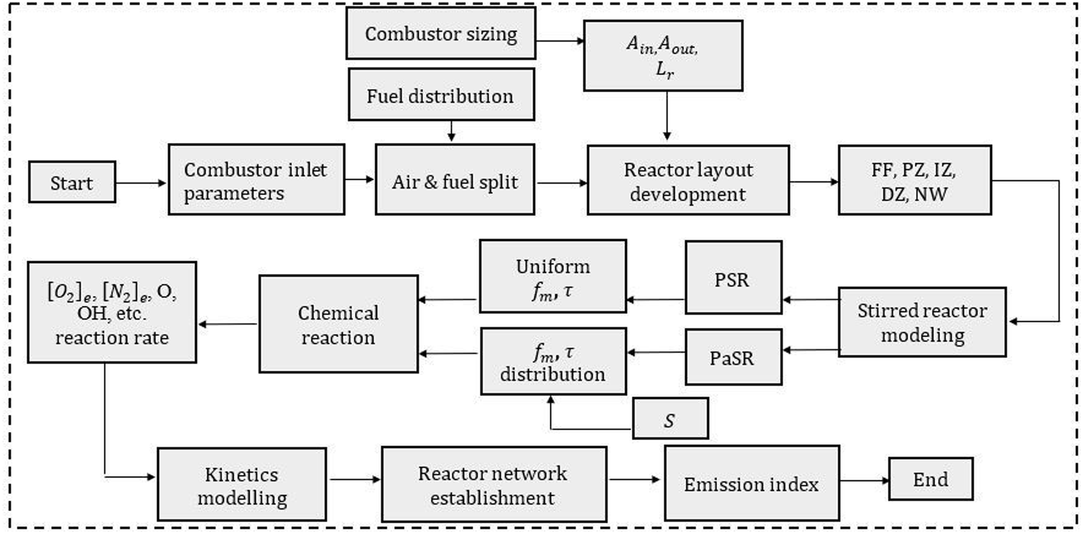
The details of the developed emission algorithm using the stirred-reactor approach (Figure 2) are presented as follows:
The combustor inlet aerothermal parameters are used as inputs. The air and fuel splits into each combustor region are defined based on the flow distribution calculation in ‘Flow distribution’ section. The combustor architecture is represented by reactor layouts. These include the definition of different zones that varies from combustor configuration. The dimensions of the zone and reactor are defined based on the combustor sizing algorithm in previous subsection. For reactors in the same zone, the inlet and outlet areas are defined based on the mass flow fraction. The stirred reactor method is developed. Two reactors are implemented: perfectly stirred reactor (PSR) and partially stirred reactor (PaSR). The main differences between the two are distinguished by their mixing characteristics. For PSR, it is assumed that the mixing is instantaneous, uniform and ideal inside the reactor. The mixing characteristics are represented by two parameters: mixing fraction Emissions calculation process. Then, the NOx formation rate is predicted. The thermal NOx calculation is based on the Zeldovich mechanism and the contribution of The kinetics calculation assumes that the Zeldovich mechanism is decoupled from the main combustion process. Thus, the temperature, the concentration of species in equation (11) can be determined using the local chemical equilibrium values. Once the reactor is formulated for each zone, a network is established to connect each element and enable the chemical reaction taking place along the combustor. In the present study, axial networking is applied to simplify the modeling of the flow field. It could be further refined if detailed knowledge flow mixing characteristics is known. The emission index and other parameters (e.g. temperature and gas density) are obtained as outputs at the exit of the reactor.


Heat transfer and cooling
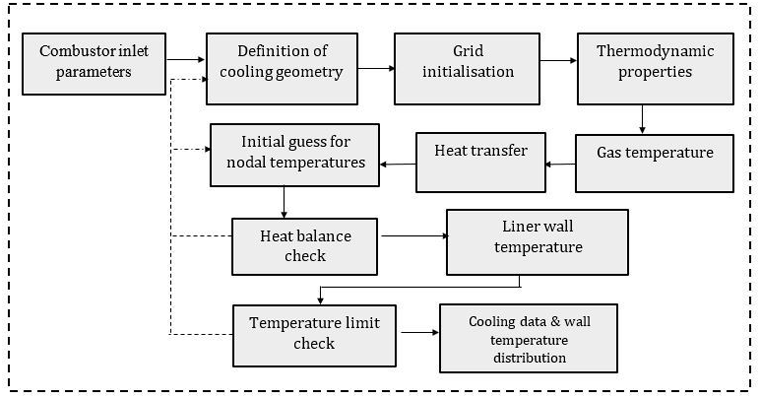
The procedures (Figure 3) for calculating the heat transfer and liner wall temperatures are presented as follows:
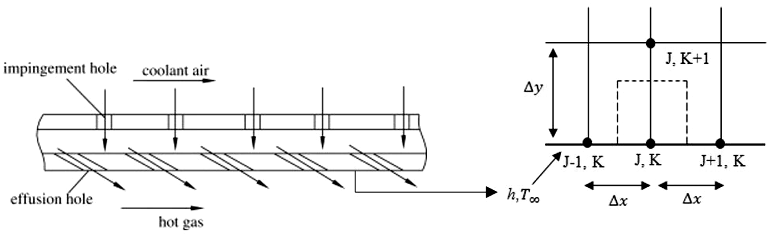
The calculation process initially receives The cooling geometry is determined based on the cooling system design under the sizing algorithm (‘Combustor sizing’ section). In particular, the cooling segmental length The domain of interest is discretised into nodal points and elements in x and y directions. For an element on the outer surface of the cooling liner (Figure 4), the central node is symbolled as (j, k). The surrounding left, right and upper nodes are denoted as (j − 1, k), (j + 1, k), and (j, k + 1), respectively. jlocations indicate the xincrement and klocations indicate yincrement. The thermodynamic properties’ calculations include determining the specific heat capacity Heat transfer and cooling analysis- Finite Difference Method. Combined cooling system- nodes with radiation and convention boundary. The combustor zonal gas temperatures are calculated in the emission algorithm. Eric Goodger’s method is used.
20
The approach is capable of determining the gas temperatures for any carbon-hydro non-dissociated mixtures and dissociated mixtures. For dissociated all mixtures at higher temperatures, the degree of dissociation is temperature and pressure dependent. Hence, for all mixtures, the reaction is defined as
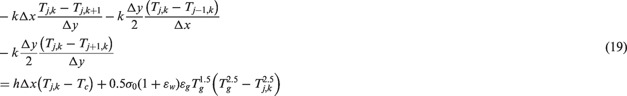
Heat transfer analysis is assumed to be constant around the circumferential direction at any axial location. Figure 4shows a section of hot liner, a combined impingement and effusion cooling system. Under steady-state conditions, the analysis is restricted to the hot liner wall surface. Based on the governing equation, conservation of energy, for an element with the inside surface The element shown in Figure 4is subject to conduction (upper, left and right) radiation and convection (bottom) boundary conditions; the energy balance is applied to the central node (j, k). Thus, the discretised form of energy balance using FDM becomes
The temperatures at nodal points are numerically solved. The convergence criterion for obtaining the correct temperature is the heat balance on each node
Iteration of the geometric parameters is required if the liner wall temperature exceeds the temperature limit of the liner material.


Performance
A semi-empirical approach is proposed to evaluate relight efficiency. Initially, the mass flow, pressure, and temperature at altitude relight condition (i.e., windmilling condition) are estimated. The estimation requires the knowledge of the following input parameters:
Maximum flight altitude, Mach number Maat the maximum flight altitude Engine inlet area, Bypass ratio at the design point, Overall pressure ratio at the design point, Specific take-off thrust under sea level static condition,
Next, the combustor inlet windmilling pressure and temperature can be estimated based on windmilling performance data in Walsh and Fletcher.
13
It should be noted the data are valid for turbojet. The factor is introduced to correct the pressure ratio and temperature ratio for turbofan application

BPRdenotes the engine bypass ratio
Hence, the pressure ratio for turbofan is defined below

Similarly, the temperature ratio for turbofan is defined as

The combustor windmilling inlet mass flow can be estimated based on airflow function defined in equation (24). It requires the information for specific thrust under sea level static condition and Mach number during windmilling


The combustor inlet mass flow can be finally estimated by assuming the BPR under windmilling condition is around 16 times the BPR at the design point. Once the windmilling parameters are available, the combustion efficiency level at the condition can be evaluated using the loading parameter defined in equation (3). The relation is defined in equation (26)
13
The above relation can be also used to assess the efficiency level at design point and other engine operating conditions, by substituting the corresponding combustor inlet parameters into the loading parameter.
Case studies
Aerodynamic sizing
Design-point inlet parameters.
The flow distribution, main combustor dimension and injector information are in Table 6. For GEnx-TAPS and E3-DAC, part of geometric data is available in Foust et al.
3
and Burrus et al.
22
With the available geometry (Figure 5), the actual dimensions for the remaining part of the combustor can be estimated by scaling. For comparison, the calculated results are also listed in the same table. For the rich-burn combustor (i.e., CFM56), the design-point dome equivalence ratio is calculated to be 1.3. The ratio is estimated to be 0.6 for the lean-burn cases (i.e., GEnx and E3).
E3-DAC and GEnx-TAPS combustors [3][22]. Flow distribution, combustor dimension and fuel injector data comparisons. Measured data.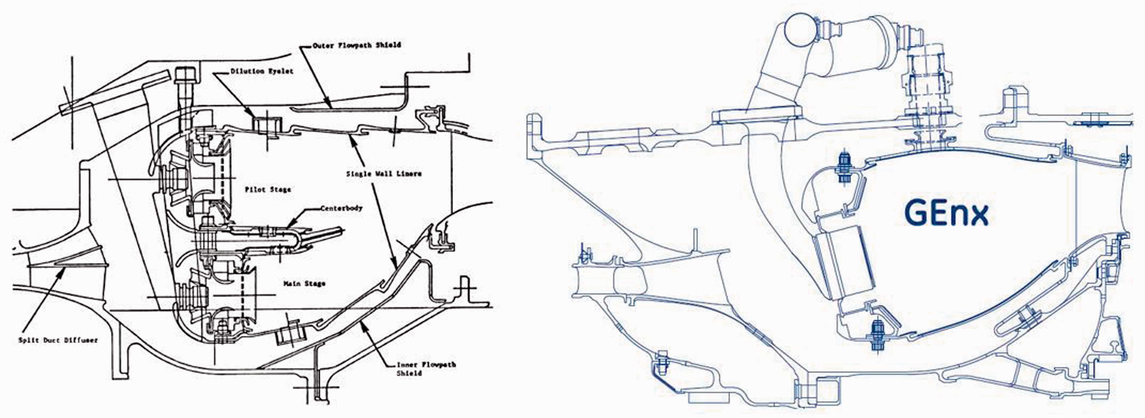
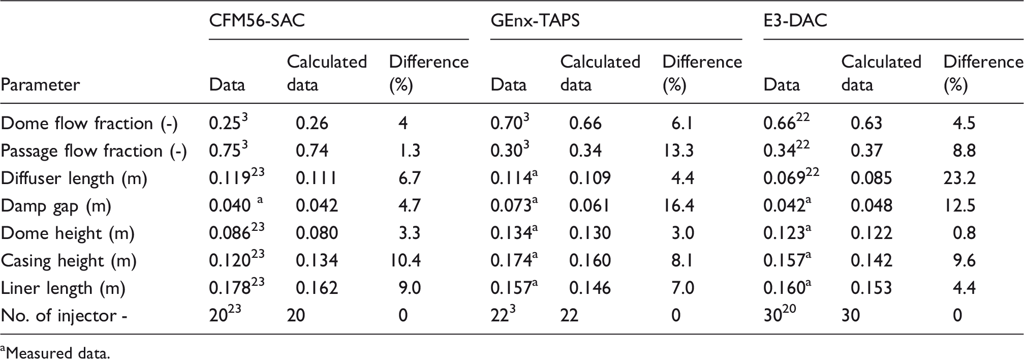
The results, in general, produce feasible dimensions and display reasonable agreement with the data. Most of the differences between the calculated results and data are within 10%. A notable deviation occurs in the calculation of diffuser dimensions (i.e., GEnx-TAPS case). A small dump gap is believed to prevent flow separations in the faired diffuser. However, further reduction of the gap would lead to excessive local acceleration and a large flow turning angle, thereby increasing pressure loss. Since the effect of the dump gap on flow distribution and pressure loss is not studied in this case, the current study estimates the value to be two times the combustor inlet height. Split flow diffuser is used in E3 design. The study reveals that a 50% reduction in pre-diffuser length can be achieved compared to a single passage configuration having the same AR.1,22The current design considers a single passage configuration, which results in a longer dimension.
Emission
The emissions are assessed on the same combustors in previous subsection, based on the available geometrical and performance information. The reactor layouts are shown in Figure 6. The overall reactor layout for the SAC version (i.e., CFM56) was created. Flame front zone is modelled by PaSR to take account of the inhomogeneous effect of mixing owing to diffusion-based combustion. The downstream zones are simulated by two PSRs considering the mixing process is enhanced due to air addition and increase of the flow residence time. A mixer is used to model the combustor exit. For E-3 DAC combustor, the network is established similarly to SAC but radially arranged. For internally staged configuration (Genx-TAPS), PaSR is chosen to model the diffusion combustion in the primary zone, and PSR is used to model the premixed combustion at the main stage. Near-wall cooling has a significant effect on emissions for this type of combustor.
1
Thus, near-wall reactors are created to model the lower gas temperature zone.
Reactor layout representaion for SAC (top left), DAC (bottom left) and Internally staged configuration (right).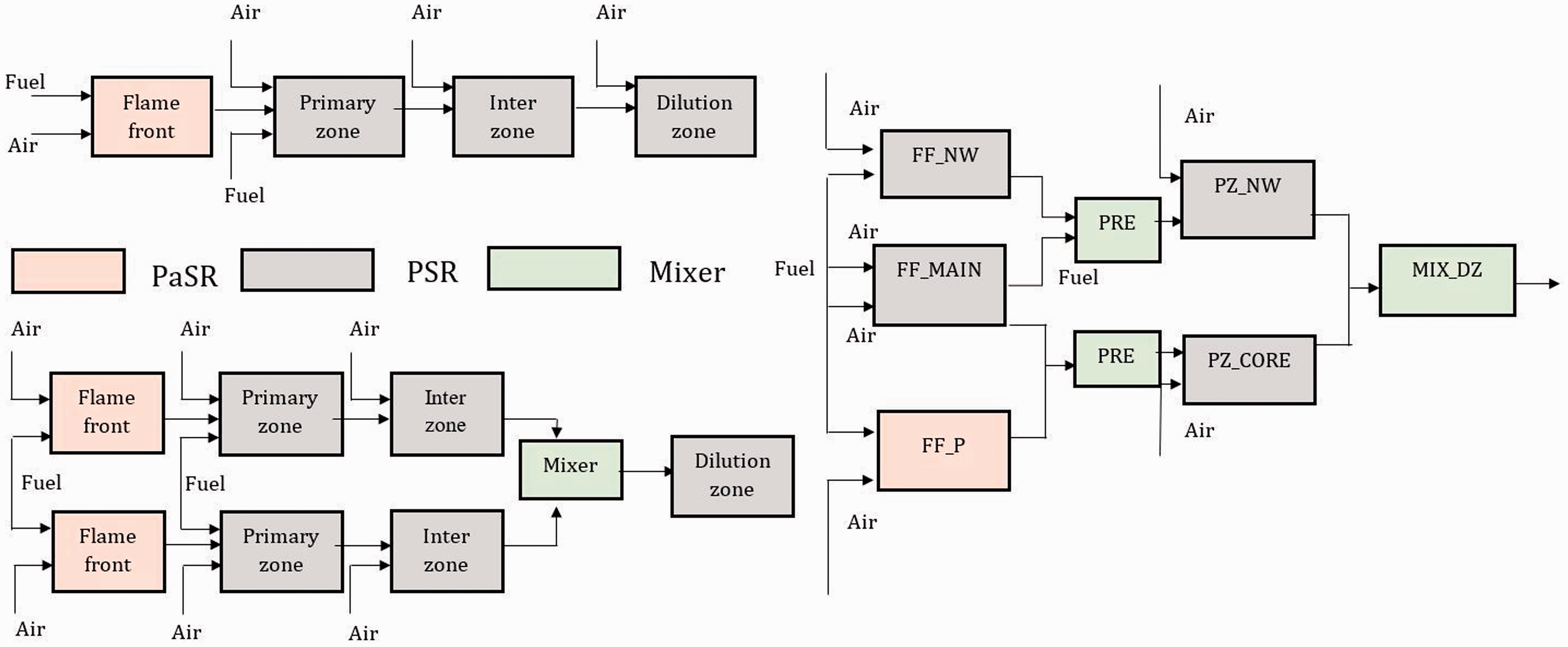
A comparison was made between the predicted results and the experimental data in ICAO emission data bank.
26
The experimental results are measured under the four operating modes (idle 7%, take-off 100%, climb-out 85% and approach 30%) at sea level, static and standard day conditions. The results show a reasonable agreement with experimental data in predicting NOx emissions at engine key power conditions (Figure 7). Overall, the predicted results display a slight underestimation of the measured values. One of the reasons is from the kinetics calculations: for thermal NOx calculations, the Zeldovich mechanism is assumed to be decoupled from the main combustion process, by using the local equilibrium values of temperature, stable and free radicals (e.g. Emission index- experimental data vs calculated results.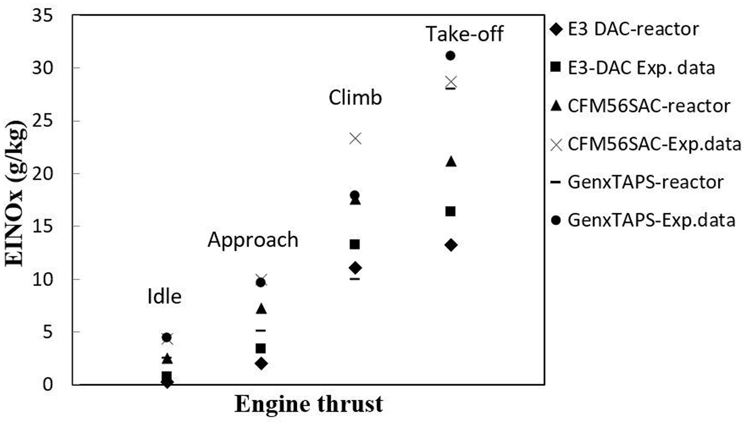
Heat transfer and cooling
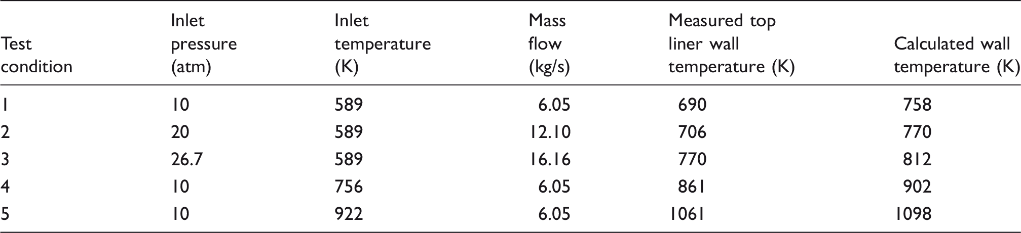
Measured liner temperature vs. predicted liner temperature at different powers.
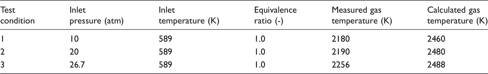
Comparisons between measured and calculated gas temperature.
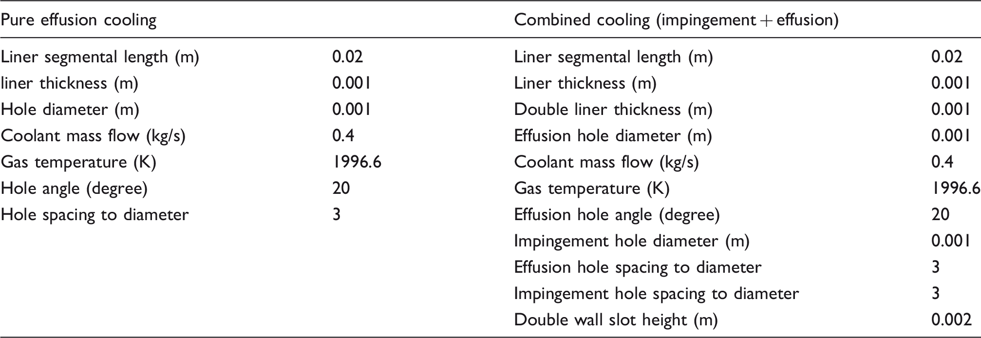
A second case study was conducted to verify the FDM approach. Two advanced cooling technologies were investigated (Table 9): Combined impingement and effusion cooling (Figure 4) and pure AEC (absence of impingement wall). The geometries for the effusion cooling remain the same for the two cases. Figure 8shows the calculated axial temperature distribution along the combustor liner. The analysis is restricted to a single cooling row. At the front sections, both cooling technologies yield similar temperature profiles with the temperature initially decreasing axially. The higher wall temperature for the combined system is due primarily to the cooling air takes the heat from the impingement along the backside of the liner surface before reaching the effusion holes. Downstream of the effusion hole, since the turbulence mixing process promotes the heat transfer process from the hot gas to the coolant, the cooling effectiveness decreases. This results in the increase in liner wall temperature, for both cases. With the presence of the jet impingement, the temperature can be reduced locally such that the overall peak temperature is minimised. The double-wall system gives a more efficient cooling performance than pure effusion.
Liner wall temperature distribution for two cooling technologies. Geometric and input parameters for two cooling technologies.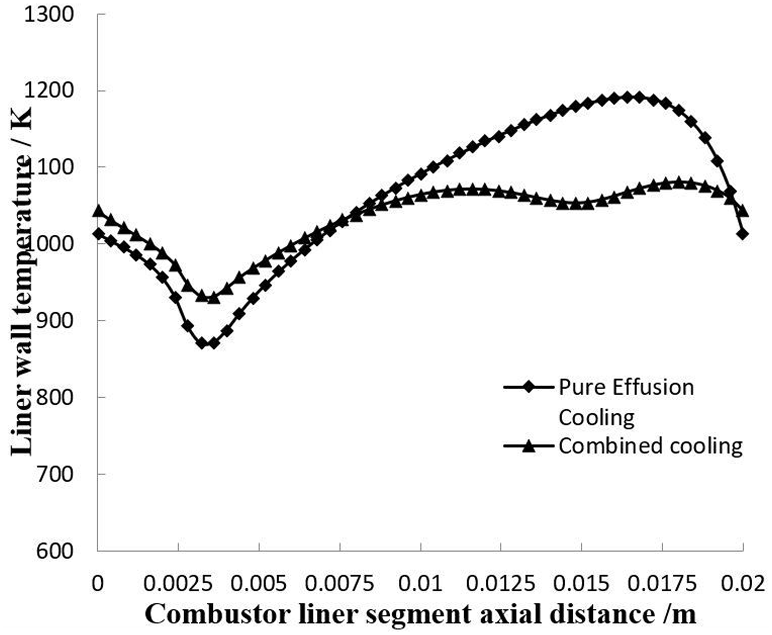
The case studies show that the heat transfer calculation is believed to evaluate liner wall temperature with reasonable accuracy. The developed FDM is capable of capturing a two-dimensional global prediction on liner temperature distributions for different cooling systems, as well as producing the physically sensible temperature predictions. It could be of use in the rapid identification of design solutions as well as initiating the optimisation of the design variables.
Performance
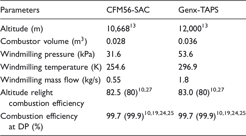
Performance prediction at altitude relight and design point.
Methodology application
Conceptual lean staged combustor
Combustor inlet parameters and design targets at DP condition.
The framework enables the automatic design process for the development of a conceptual lean staged low emissions combustor (Figure 9). The combined faired and dumped diffuser configuration is chosen to reduce the inlet flow Mach number with minimised pressure loss. All the air for combustion enters through the fuel–air mixer. Fuel staging is employed to address the low power stability issue, with local pilot stage equivalence ratio at idle close to stoichiometric value. Table 12shows the air and fuel distribution results. The primary hole and dilution zone are eliminated since the mixing is primarily achieved via the fuel–air mixer. The centre recirculation zone is established by the dome swirlers. The dome height is reasonably increased to reduce the dome airflow velocity, which promotes stable ignition and combustion, especially during the engine altitude relight. For the fuel–air mixer, the pilot stage adopts non-premixed combustion which effectively reduces the flashback risks. The pilot mixer comprises a pressure swirl atomiser, a two-stage air swirler, and a Venturi assembly. The primary swirler is responsible for fuel atomisation and the secondary swirler is to control the flow structure. The pilot swirling strength is sufficiently raised to initiate a relatively wide cone angle from the pilot outlet, which improves the ignition performance. In this case, the pilot overall SN is 0.6.
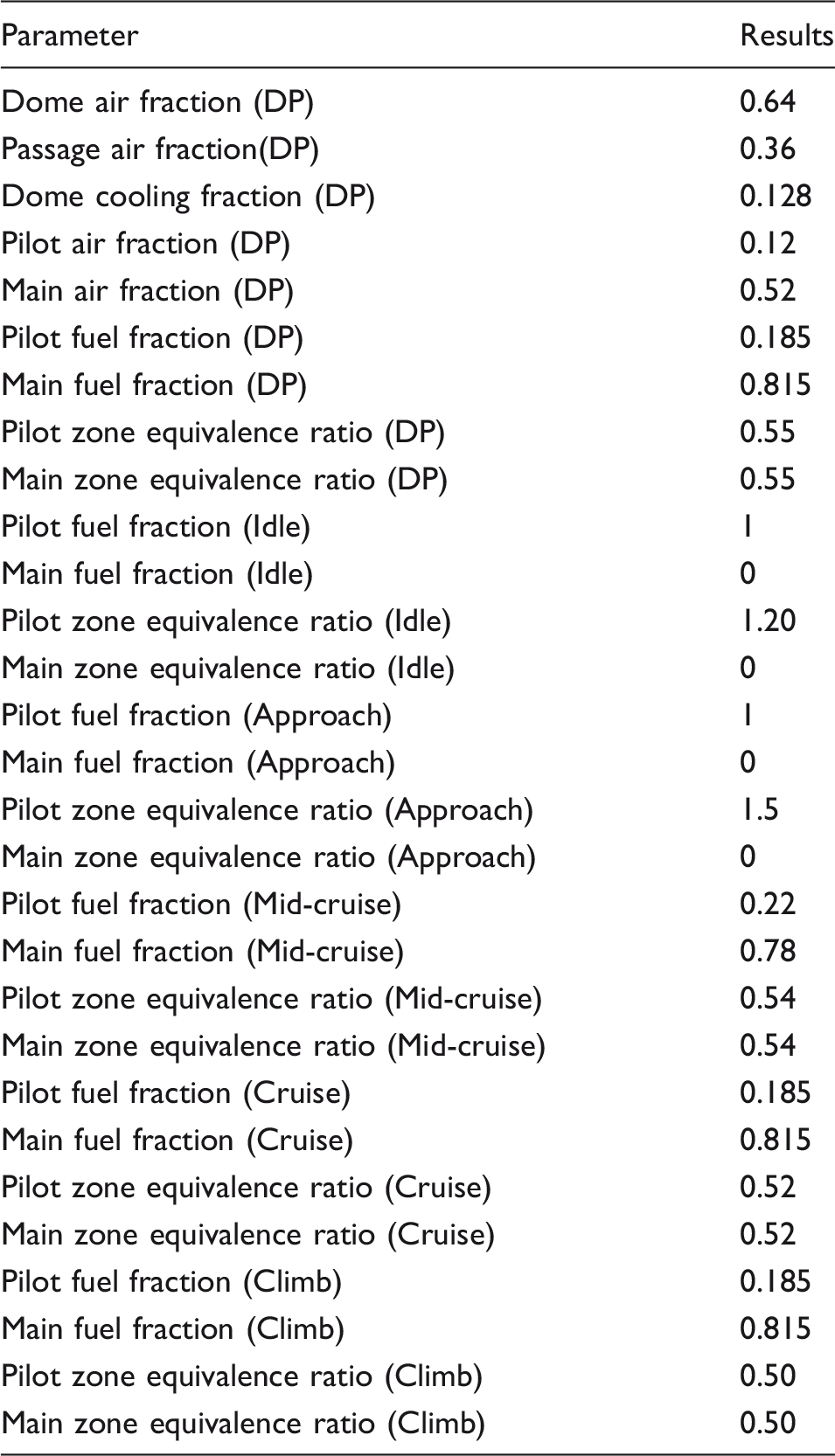
Designed conceptual lean staged combustor. Air and fuel split results.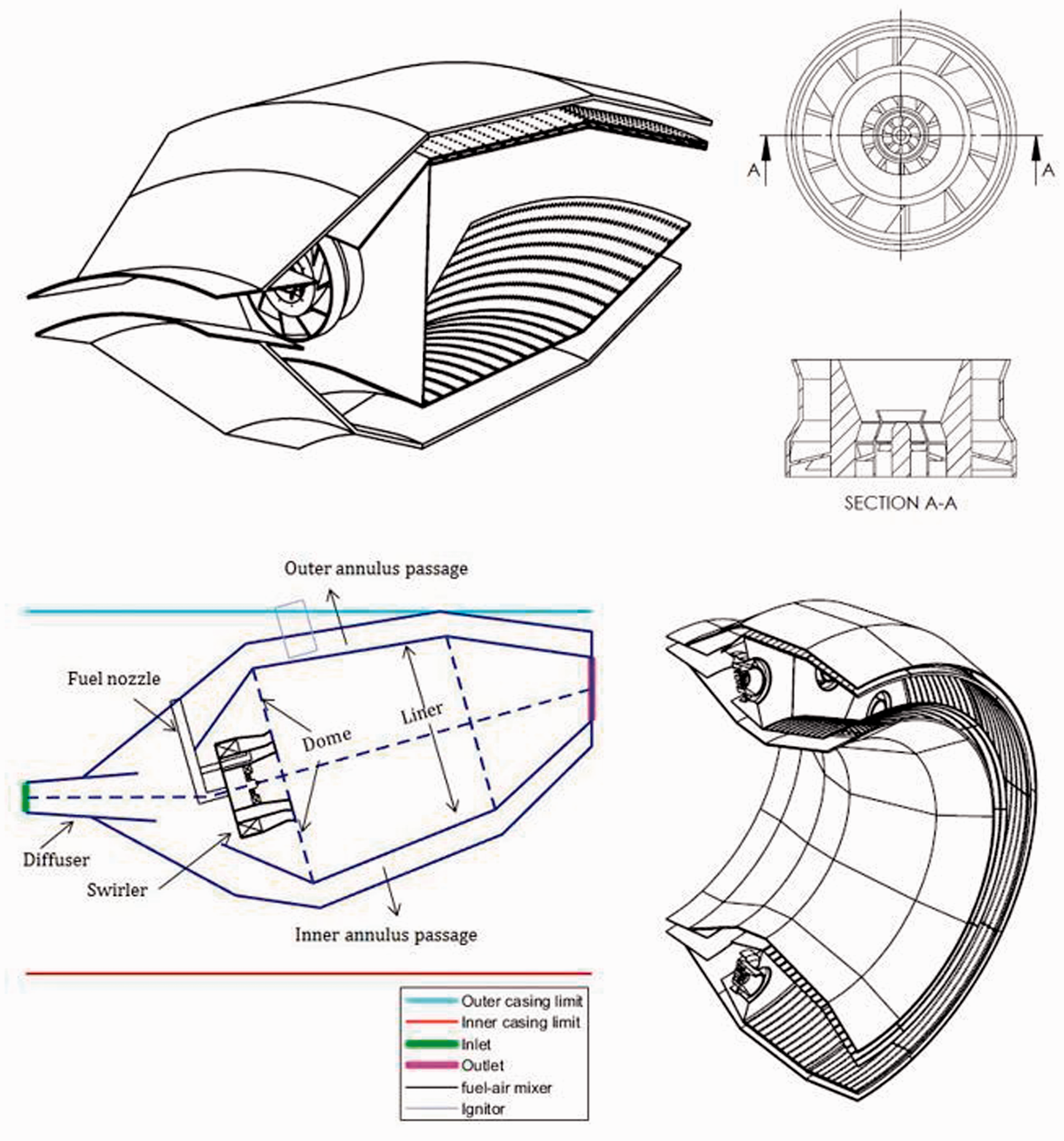
For the main stage, the current design employees partially premixed combustion. It consists of a mixing chamber, a fuel–air mixer that combines the multi-point cross-flow injection with an axial type of the air swirler. The number of the fuel orifice in cross-flow is equal to the number of the swirler vane, which is to enhance mixing in the circumferential direction. To control the auto-ignition, the mixing chamber of the main is designed such that the mean flow residence time does not exceed auto-ignition delays. A safety factor of 2 is imposed. The swirling strength of the main stage is reasonably reduced to some extent so that the axial flow speed along the centreline of the mixer can be increased to provide the resistance of the vertex bubble from moving upstream. Thus, the flashback can be effectively reduced. In this case, the SN of the main is around 0.45.
The impingement with AEC is selected for the outer liner. For the inner liner annulus, the AEC is adopted. For the effusion system, the hole angle is 20° and the hole diameter is around 0.7 mm. The spacing to the hole diameter ratio is around 4. For impingement system, the hole has a similar dimension, the impingement location is 0.75 of the total segmental length.
Design evaluation
Emissions
The emissions are assessed based on the developed physics-based method. Overall, the designed combustor produces NOxemissions increasing with power settings (Figure 10) with take-off EINOxpeaks at 8.2 g/kg. The exception is at mid-cruise. During mid-cruise, since the fuel is consumed during flight, the aircraft body is getting lighter. Therefore, less mission fuel is required. This results in a leaner burn in the combustor primary zone. In order to alleviate the risk of lean blowout, the fuel schedule (Figure 10) is employed such that part of the main is turned off. With this strategy, the local equivalence ratio and thus flame temperature can be raised. The result indicates the emission level is less than idle emission, which results from the local richer burn at the pilot only operating mode.
NOx emission at key engine power conditions and fuel schedule mode.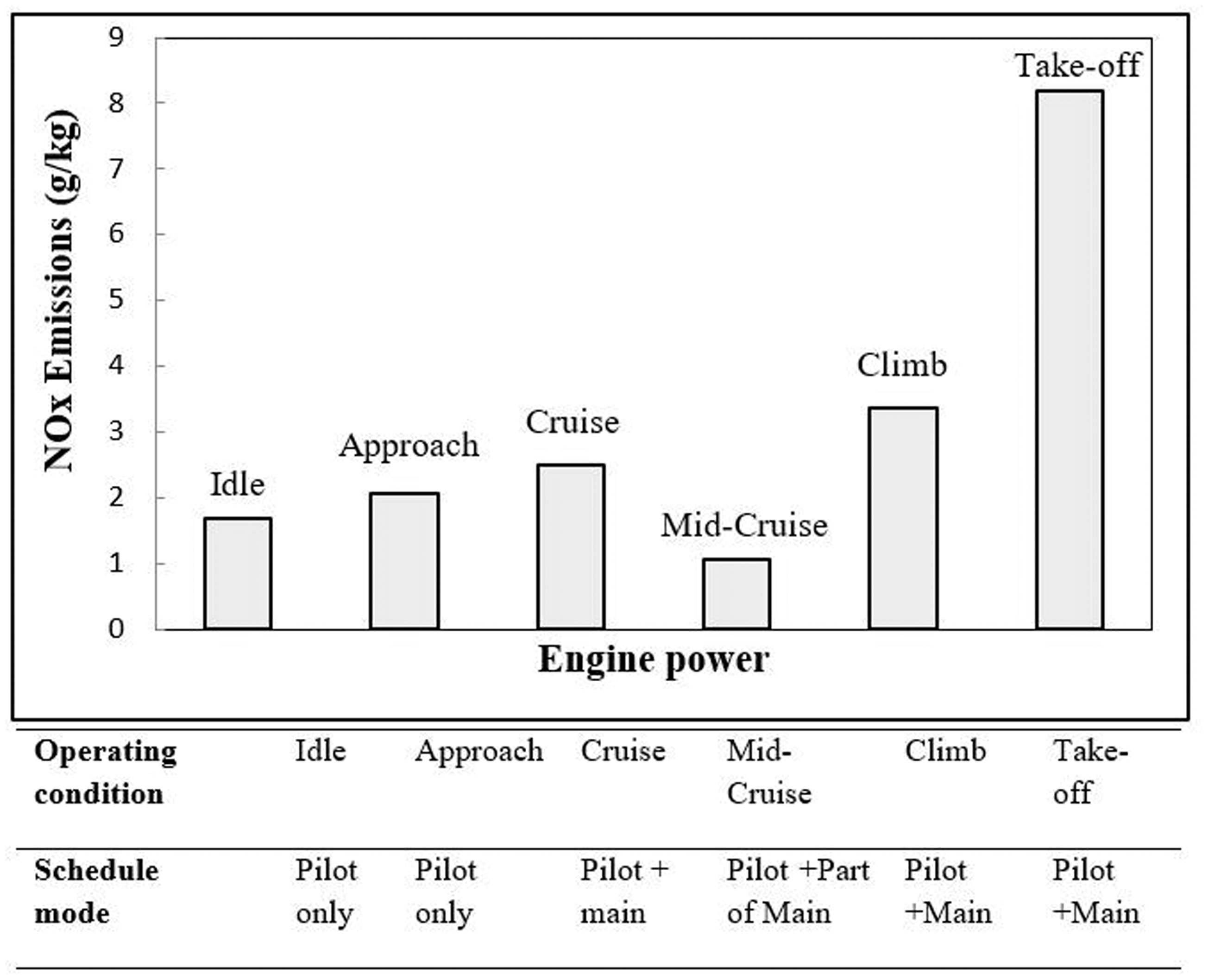
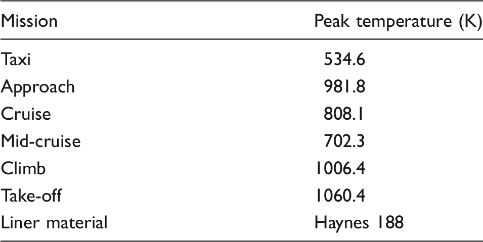
Liner wall temperature
Liner wall peak temperature at different engine thrust conditions.
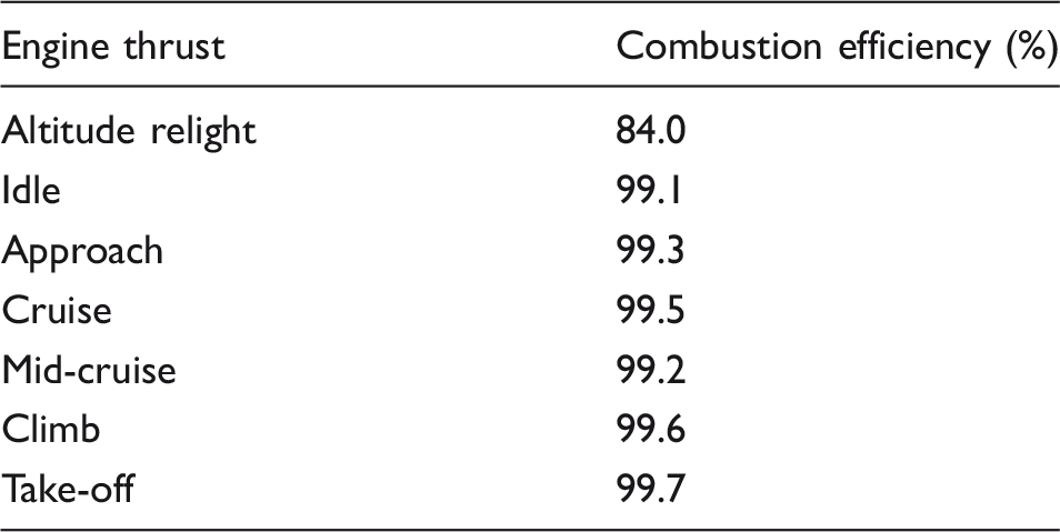
Performance
Performance evaluation for the designed combustor.
Sensitivity analysis
Sensitivity analysis – impact of assumed variables on design outcomes.
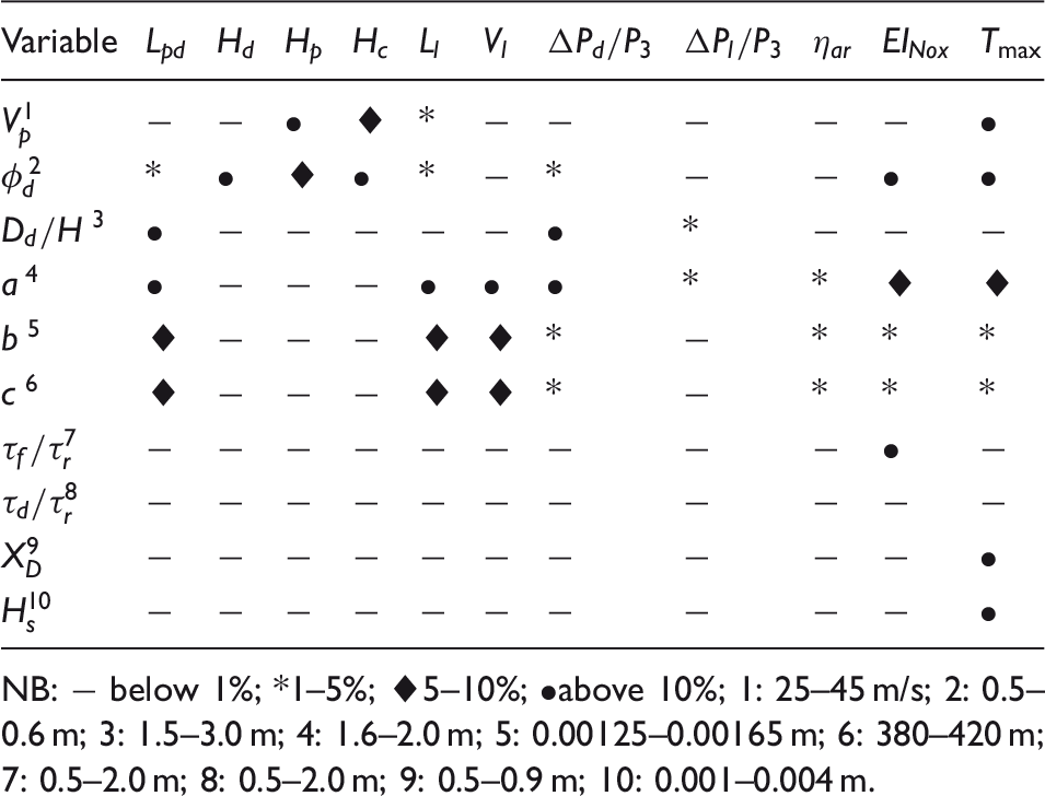
NB: − below 1%; *1–5%; ♦5–10%; •above 10%; 1: 25–45 m/s; 2: 0.5–0.6 m; 3: 1.5–3.0 m; 4: 1.6–2.0 m; 5: 0.00125–0.00165 m; 6: 380–420 m; 7: 0.5–2.0 m; 8: 0.5–2.0 m; 9: 0.5–0.9 m; 10: 0.001–0.004 m.
The change in passage velocity Vpmainly impacts on passage and casing dimensions. In terms of combustor performance, the liner wall temperature is dramatically affected due primarily to the influence of external convection of the liner.
The design variable dome equivalence ratio
The dump gap Ddwas assumed in the initial calculation. This parameter has a notable impact on the geometry of the pre-diffuser and hence the pressure loss.
The dimension of the combustor volume was evaluated using the semi-empirical loading parameter that is valid for the specific combustors. The pressure- and temperature-dependent coefficients in the parameter can vary for different combustors types. The values initially used in the calculations are a = 1.8, b = 0.00145, and c = 400. 13 Analysis indicates that the pressure-dependent coefficient, ais the most critical term that impacts the combustor sizing as well as emission and liner wall temperature due primarily to the change in flow residence time and coolant mass flow per unit of liner surface area.
Axial networking was applied in the emission calculations, and the flow recirculation effect is not explicitly modelled in the physical-based method. In this analysis, the effect of flow recirculation on NOx emission is studied by varying the reactor flow residence time τ. It can be observed that the emission level is mainly governed by residence time in the flame front zone
The geometrical cooling design variables: impingement location and double wall gap both lead to notable impact to the cooling performance.
Optimisation study
There are a number of conflicting design targets that exist in combustor design. The conventional iterative process by changing the design variables is inefficient to give optimum solutions. Therefore, multi-objective optimisation techniques are used to address the issue with conflicting requirements especially when one (or more) could not be met.
The designed combustor in previous section indicates that the combustion efficiency and liner temperature meet the design requirement. However, the NOx emission is greater than the required value. The optimisation was conducted at the design point. By conducting the parametric analysis at the design-point condition, the combustor meets the required efficiency level. Therefore, a focus is placed on the emission and liner temperature. For smaller gas turbines, the air mass flow is reduced and the ratio of combustor surface area to volume is relatively large, both result in a challenge in combustor liners cooling. In addition, a large proportion of the airflow is employed for lean combustion to control NOxemissions. This also leads to less air available that is challenging to maintain the low liner temperature. The notable conflicting design requirements lead to the optimal use of air and change of cooling geometries to control the emission and liner wall temperature.
Based on the classification of the optimisation problem, the current optimisation work is classified as (1) non-linearity, the problem to be solved presents a non-linear behaviour, and it is believed to be non-smooth and non-differentiable; (2) multi-objective, two objectives are to be investigated in this optimisation study, namely the NOx emission and liner wall temperature; (3) constrained, the parameters are constrained with certain ranges to limit the objective space; (4) real values: all variables in the optimisation problem are real numbers A controlled elitist genetic algorithm optimiser, a variant of NSGA-II, is incorporated in the current framework.
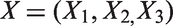
Input Since the design process can be automated using the optimisation techniques, the following design parameters should be considered as inputs:
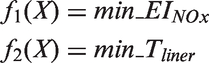
Combustor inlet/outlet Combustor architecture Fuel type, fuel mass flow Inlet/outlet pitch location and flow area Geometrical constraints of the combustor Objectives As mentioned above, as the current design meets the efficiency requirement, the main objectives in this design are focused on combustor emission and liner temperature. Therefore, the fitness functions Xis a vector that contains design variables The first objective function Variables The sensitivity study (previous subsection) indicates that the dome airflow distribution greatly impacts the emission and liner temperatures. Hence, the primary zone airflow parameter is selected as an optimising variable. The geometrical parameters affect cooling performance. As mentioned in ‘Combustor sizing’ section, during the cooling geometry calculations, the axial impingement position and height of the double-wall cooling are assumed design variables. From the sensitivity analysis, both parameters display sensitive behaviours and have substantial impacts on the liner temperature. Therefore, they are also selected as main variables in the optimisation process. Thus, the defined variables are
X1: a fraction of the air mass flow in the primary zone X2: the axial location of the impingement XD, namely the ratio of the distance from the trailing to the diameter of the cooling hole Coupled algorithms In order to find the optimum solutions to achieve the combustor emission and liner temperature goals, the related design tools should be integrated to conduct the optimisation task. Thus, the following algorithms are coupled in this problem:
Flow distribution Combustor sizing Emission Heat transfer and cooling Optimisation Constraints Based on the current design criteria which require the NOx emission at take-off condition is below 6 g/kg and the maximum permitted liner wall temperature is 1123 K, these two parameters are constrained in non-linear inequality form
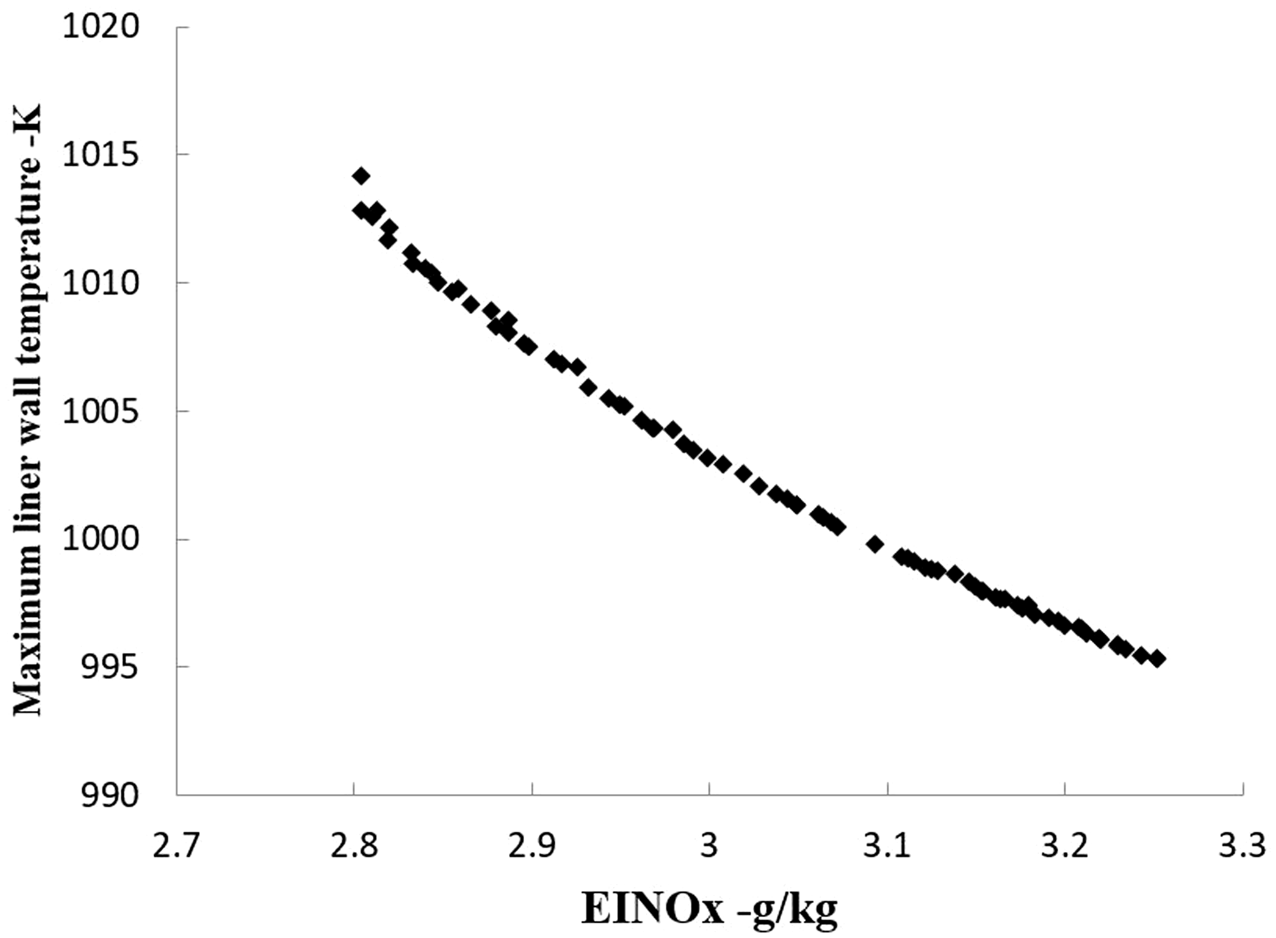
Tmis the maximum temperature identified in the combustor liner The stall generation is set to be 100, and the function tolerance is 1e − 4. Both setting parameters were tested and produce non-sensitive solutions. The optimiser produces the solutions shown in Figure 11. The shape of the Pareto front illustrates the objectives are in the form of the conflicting nature. The set of the optimal solutions yields the maximum liner wall temperature ranging from 995 to 1013 K and the NOXemissions from 2.8 to 3.25 g/kg. The produced sets of solutions satisfy the target at the design-point condition. The ranges for the corresponding design vectors are: Pareto front for NOx emissions vs Maximum liner wall temperature. It should be noted that the solutions are non-dominated and each point on the Pareto front curve can be regarded as an optimum solution. For selecting the final optimum point, decision making is required. This process is dependent on the personal choice of the designers and not further considered in the present work. However, some multi-attribute decision-making methods are available to help the designer to determine the final optimal point. These include additive utility method,
32
technique for order of preference by similarity to ideal solution method
33
and concordance and discordance analyses by similarity to ideal designs (CODASID) method.
34
Overall, the optimisation study using the developed methodology indicates that the developed work has the potential of identifying and resolving the potential design challenges at the early stages of the design process. In the future development, more design objectives (i.e., altitude relight combustion efficiency and outlet temperature distribution) will be coupled in the framework to allow more design variables to be optimised.


Conclusions
A detailed preliminary design methodology was developed for modern low emissions aero combustors. The inter-related design elements involving aerodynamic sizing, heat transfer and cooling, emission and performance are coupled in the design process. Different approaches are provided in detail.
Case studies were performed to assess the feasibility of developed work. The developed combustor sizing methodology produces reasonable combustor dimensions against real low emissions combustors in the public domain, namely CFM56-5SAC GEnx-TAPS, and E3-DAC combustors. The difference between most of the results is below ±10%.
The developed physics-based method is used to predict chemical emission. It provides a good agreement with experimental data, with the capability of producing a reasonable trend to represent the NOx emissions as a function of engine power setting.
The case studies show that the heat transfer calculation is believed to evaluate liner wall temperature with reasonable accuracy. The FDM is developed and applied to the modern cooling system (effusion, and impingement + effusion). It is useful to identify to the potential peak temperature (and location) hence liner durability prediction; the physically sensible trends resulting from the parametric studies indicate that the developed FDM could be used for optimisation and is capable of identifying the cooling solution in a relatively short timeframe, which is of great help in the preliminary design phase.
The methodology was then applied to design a conceptual lean staged combustor. A sensitivity analysis was performed and assess the impact of the design assumptions on outcomes. The overall performance of the designed combustor is then predicted. It shows the emission exceeds the design target. The optimisation of the air distribution and cooling geometrical parameters addresses the trade-off between the NOx emissions and liner wall cooling.
The developed design framework demonstrates the capability of rapid design space exploration and identification of different design solutions. It demonstrates the proposed methodology enables the automatic design process for the development of a conceptual lean staged low emissions combustor. The optimisation to addresses the trade-off between the NOx emissions and liner wall cooling, which shows that the developed work is capable of identifying and resolving the potential design challenges at the early stages of the design process.
Footnotes
Declaration of Conflicting Interests
The author(s) declared no potential conflicts of interest with respect to the research, authorship, and/or publication of this article.
Funding
The author(s) disclosed receipt of the following financial support for the research, authorship, and/or publication of this article: the AECC Hunan Aviation Powerplant Research Institute for funding the research.