
Abstract
The hydraulic shock absorber of a certain tractor suspension system is analyzed to determine the influence of the cross-sectional area ratio of the throttling holes of the restoration valve and the compression valve on the vibration damping performance of the whole vehicle, using a new method of machine-hydraulic co-simulation. First, the AMESim model of the hydraulic shock absorber is established, and the Kriging model is used to approximate the parameters of the AMESim hydraulic shock absorber model; the multi-island genetic algorithm and the gradient descent algorithm are used to obtain the three scenarios in which the cross-sectional area ratios of the throttle orifices of the same equivalent damping coefficients are greater than, equal to, or less than one. Then, a co-simulation model of 1/4 vehicle Recurdyn/AMESim and a co-simulation model of the whole vehicle with 162 degrees of freedom were established. The result show that, compared with the traditional method, this machine-hydraulic co-simulation method improves the calculation accuracy, calculation speed, and co-simulation model parameter accuracy. For low-speed conditions, when the throttle orifice area ratio equals 0.32, the minimum vehicle body center acceleration (root mean square value equal to 1.78 m/s2) is achieved. For high-speed driving conditions, when the throttle orifice area ratio is approximately 3.1, the minimum vehicle body center acceleration (root mean square value equal to 3.52 m/s2) is achieved.
Introduction
Due to poor road conditions in the field, such as uneven terrain, the vibration and noise of tractor operation are relatively severe, which leads to decreased work efficiency and can harm the health of personnel.1–3 Therefore, it is necessary to conduct research on suspension damping systems, of which hydraulic shock absorbers are important components of tractor suspension systems and are related to the damping performance of the suspension. 4 Hydraulic shock absorbers have obvious asymmetric nonlinear damping characteristics, and the ratio of the sectional areas of the recovery valve and compression valve determines their asymmetry.5–7 In automobile suspension design, the ratio of asymmetric damping of shock absorbers is generally set to 2-4 based on experience, 8 but the theoretical and methodological selection of this ratio has not been seen in the open literature.
Yuanyuan proposed a new mixed control strategy to supply a reference for the intelligentization of hydraulic shock absorber systems for tractors, 9 while Lielie improved the comfort of engineering vehicles by proposing an improved algorithm. 10 Both of which achieved the goal of improving comfort by improving the performance of the shock absorbers, but their approaches did not specifically address asymmetric damping.
C. Rajalingham et al. investigated the effect of shock absorber asymmetric damping on vehicle suspension travel. 10 Krishna Prasad Balike et al. investigated the dynamic response of shock absorber asymmetric damping on vehicles under ideal bumps and potholes excitations. 11 M. Silveira et al. studied the asymmetric with the objective of comfort dynamic mechanical behavior of vehicle suspensions with viscous shock absorbers. 12 J. C. M. Fernandes et al. investigated the effect of symmetrically damped suspension systems on vehicle form comfort. 13 They et al. used the mathematical models for hydraulic shock absorbers in vehicle vibration modeling.
For the convenience of designers, this paper directly studies the ratio of the sectional areas of the recovery valve and compression valve to analyze the effect of the asymmetric damping characteristics on the overall vehicle damping performance. Taking a certain type of tractor as the object, a Recurdyn dynamic simulation model and an AMESim hydraulic shock absorber model were set up and combined for simulation. 14 By using a combined optimization strategy to obtain three schemes of the sectional area ratio of the throttling orifices with equal effective damping coefficients, the influence of the sectional area ratio of the throttling orifices on the overall vehicle damping performance was compared and analyzed, and the optimal sectional area ratio of the throttling orifices was selected to provide theoretical guidance for the selection and design of hydraulic shock absorbers for tractors.
Modeling of hydraulic shock absorbers
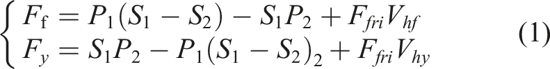
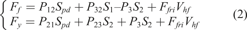
The schematic diagram of the hydraulic shock absorber is shown in Figure 1. F
f
and F
y
represent the damping forces during rebound stroke and compression stroke, respectively, while P1, P2, and P3 represent the pressures in the recovery oil chamber, compression oil chamber, and oil storage chamber, respectively. It can be expressed as follows: Hydraulic shock absorber structure diagram.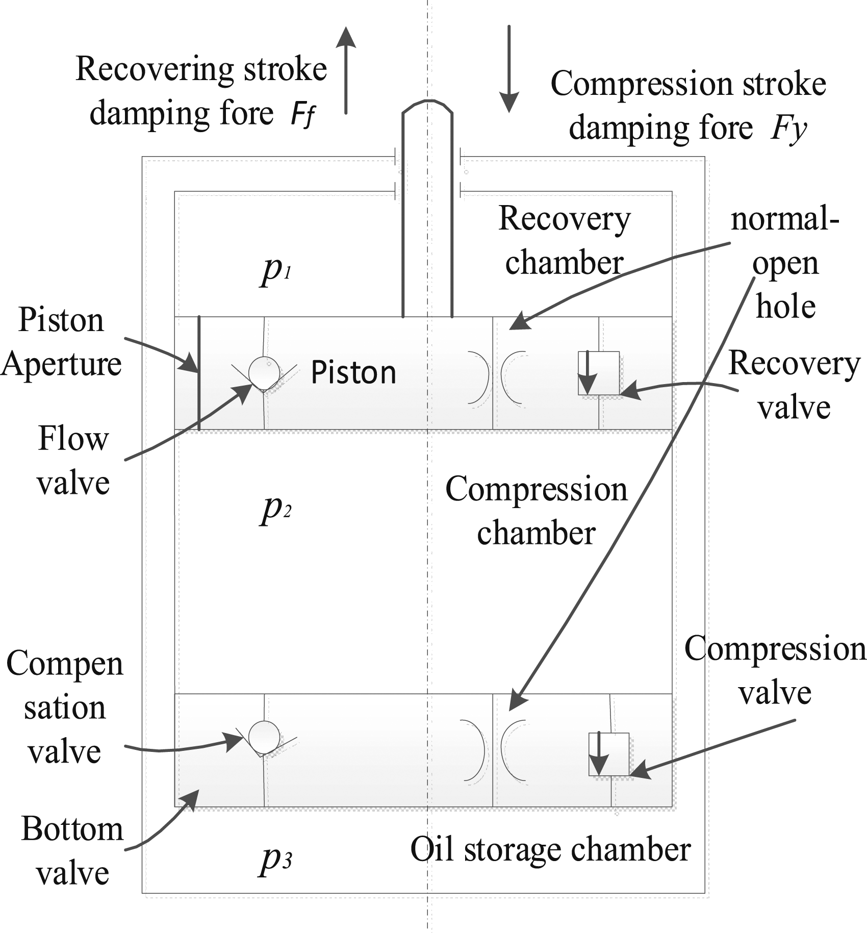
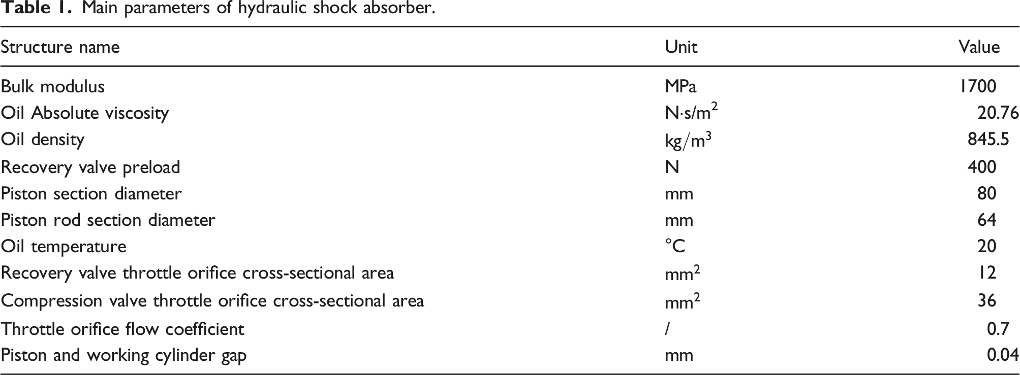
Main parameters of hydraulic shock absorber.
The mathematical model of the damping force of the hydraulic shock absorber using Simulink is shown in Figure 2, and the output curve of the damping force is affected by the flow rate, pressure difference, and other factors. Mathematical model of Simulink.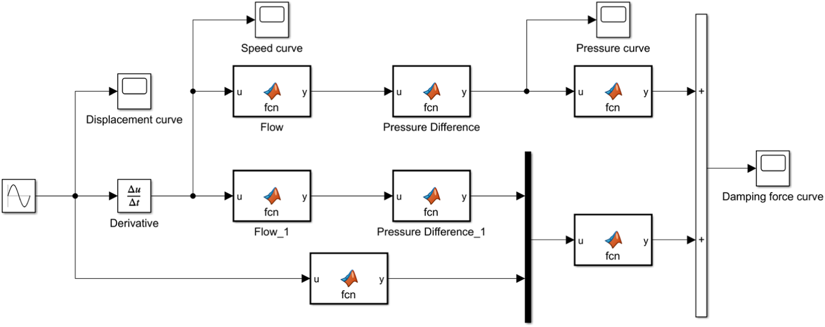
According to the hydraulic shock absorber structure sketch, mathematical model principle, model structure parameters and principle to establish AMESim model is shown in Figure 3. AMESim model of hydraulic shock absorber.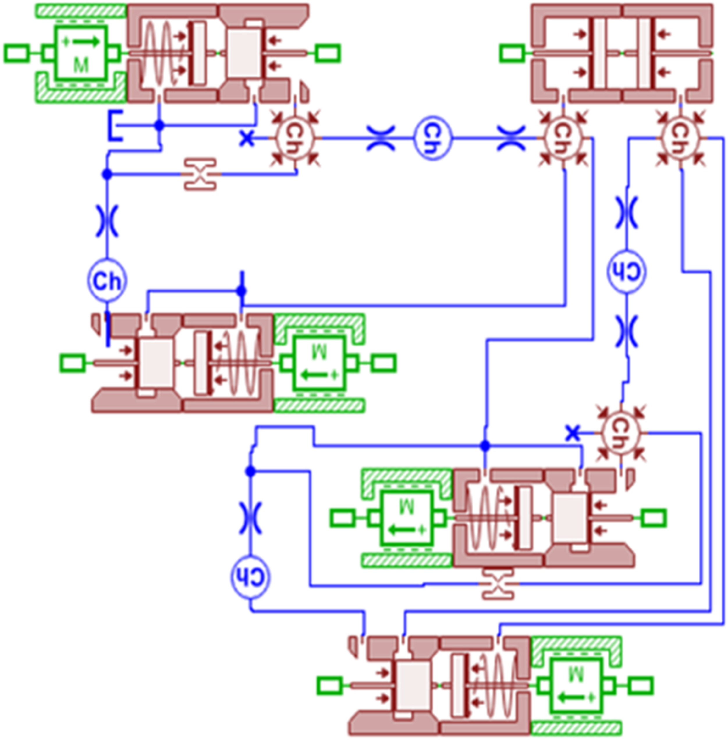
Throttle orifice hole schemes with equal equivalent damping coefficients
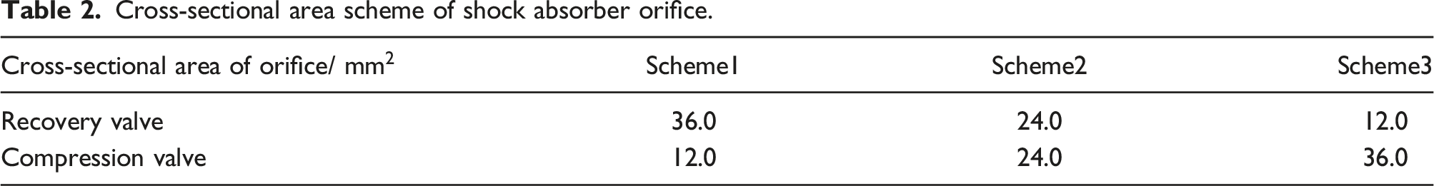
Since the cross-sectional area ratio of the throttle orifice of the recovery valve and the compression valve of the shock absorber determines its asymmetric damping, the ratio of the throttle orifice area of the recovery valve and the compression valve is defined as the asymmetric damping ratio (β = recovery/compression). In the case of equal equivalent damping coefficient, three schemes with orifice cross-sectional area ratio β greater than, equal to and less than one are proposed to analyze the influence of asymmetric damping on vehicle vibration reduction performance.
The AMESim shock absorber model is integrated with the Isight optimization software to achieve the results of three schemes with equal equivalent damping coefficients by changing the throttle orifice hole area of the recovery valve and compression valve.15–17 The Kriging model is used for approximation to improve the calculation speed of the model, and a combination optimization strategy of global and local algorithms is used for optimization.
The Kriging model is an interpolation method based on statistical theory, and its accuracy in interpolating unknown information from known information is extremely high. It generally consists of two parts: the regression process and the random process.
18
Let x0 be an unobserved point, x1, x2,… xN be the observed points around it, and the response values be y (x1), y (x2),… y (xN). The estimated value of the unobserved point is denoted by 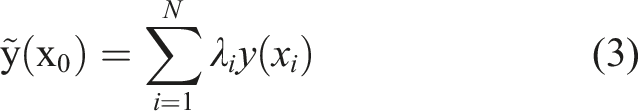
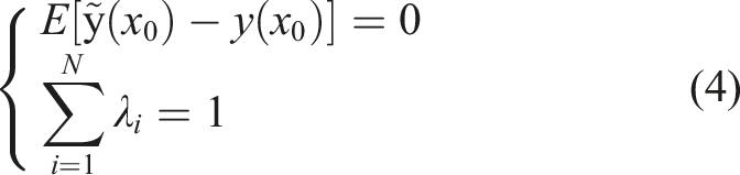
The special step in Kriging interpolation is to calculate its weight coefficients λ
i
, which must satisfy the following conditions: 1. Unbiased estimation Assuming the true value of the estimation point is y (x0), due to the actual existence of spatial variability, y (xi), 2. The variance of the difference between the estimated value
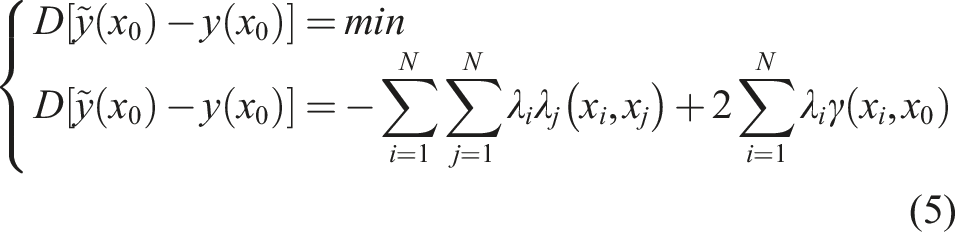
To find the minimum value of f(x), the gradient descent method is used, starting from a first point x(0), finding the direction that descends the fastest, and making it descend the most in the vicinity of the initial point, as given by the Taylor series expansion.
Due to the relationship
Therefore, the search direction p(k) in the gradient descent algorithm is the negative gradient direction 
The combined algorithm of Multi-Island Genetic Algorithms (MIGA) and Gradient Descent (GD) is used as the optimization strategy.19–21 Firstly, the MIGA is employed to locate the target extremum in the design parameter space, and then the GD is used to perform precise optimization in that region,
22
thus obtaining the optimized parameters with equal equivalent damping coefficients. Figure 4 shows the optimization process of the AMESim hydraulic software integrated in the Isight optimization software. Isight software integrates AMEsim to optimize the flow chart.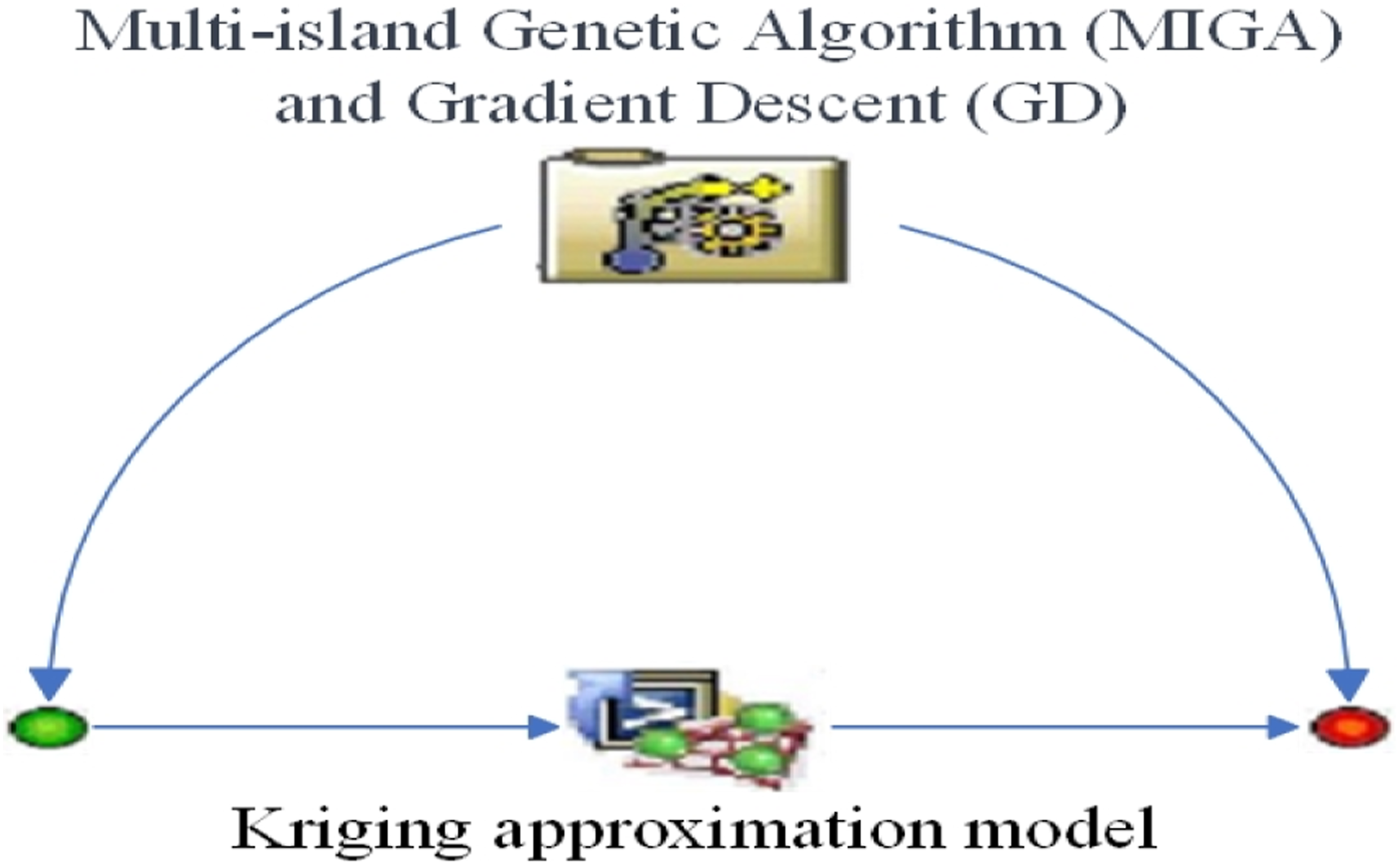
Cross-sectional area scheme of shock absorber orifice.
1/4 Co-simulation of 1/4 vehicle models
Mechanical-Hydraulic co-Simulation method
Recurdyn software specializes in the design and development of modeling of multi-body dynamics models, while AMESim is mainly a hydraulic modeling software. The co-simulation of the two can compensate for the limited accuracy of a single software simulation model. The path method of co-simulation is introduced, as shown in Figure 5, as the logic diagram of mechanical-hydraulic co-simulation. Thought of mechanical-hydraulic co-simulation.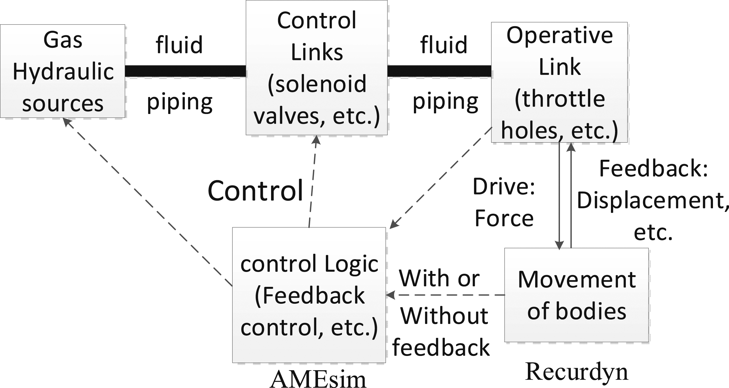
Establishment of 1/4 vehicle co-Simulation model
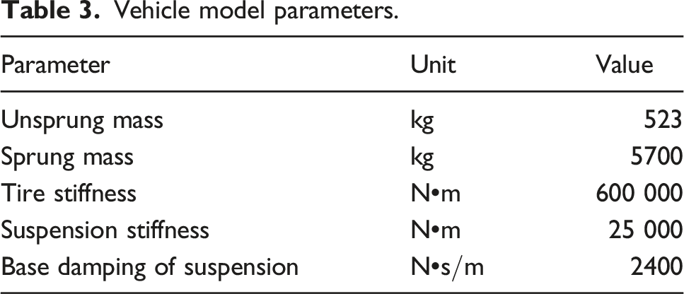
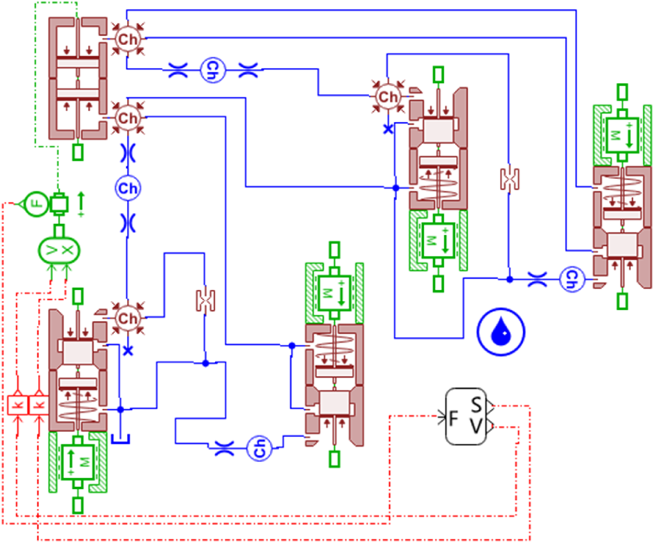
The 1/4 vehicle suspension system model is established using Recurdyn multi-body dynamics software, and the relationship between connecting pair and force is added for simulation analysis. The 1/4 vehicle suspension system model is shown in Figure 6. The suspension system model parameters are shown in Table 3. In this model, the damping characteristics of the shock absorber are output by AMESim and imported into Recurdyn software for co-simulation. The co-simulation model is shown in Figure 7. Recurdyn 1/4 vehicle model diagram. Vehicle model parameters. Co-simulation model of 1/4 vehicle model.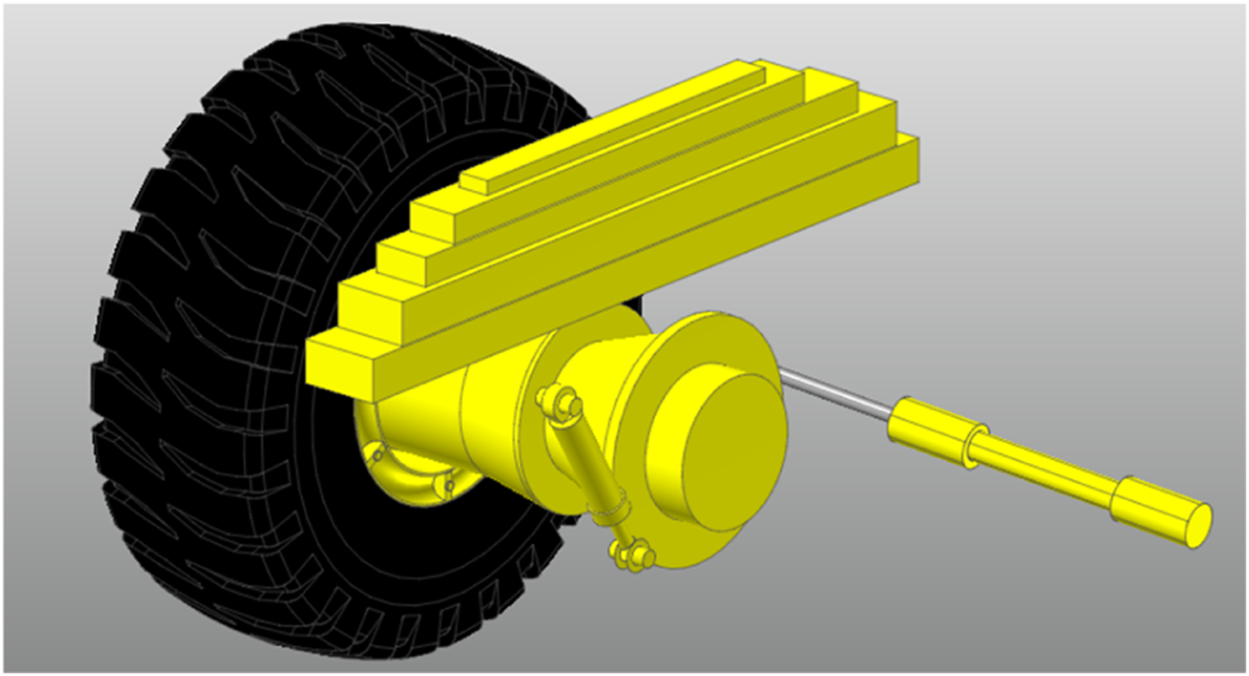
Verification of 1/4 vehicle co-Simulation model
The vibration response results of the Simulink hydraulic shock absorber mathematical model and the co-simulation model are compared. The road input is a B-class road surface with a 20 km/h speed. The time-domain curves of the vertical acceleration of the vehicle center of mass, the dynamic deflection of the suspension, and the dynamic load of the tire are obtained. The comparison results are shown in Figures 8 – 10. Comparison of suspension dynamic deflection time domain curves. Comparison of tire dynamic load time domain curves. Comparison of body centroid acceleration time domain curve.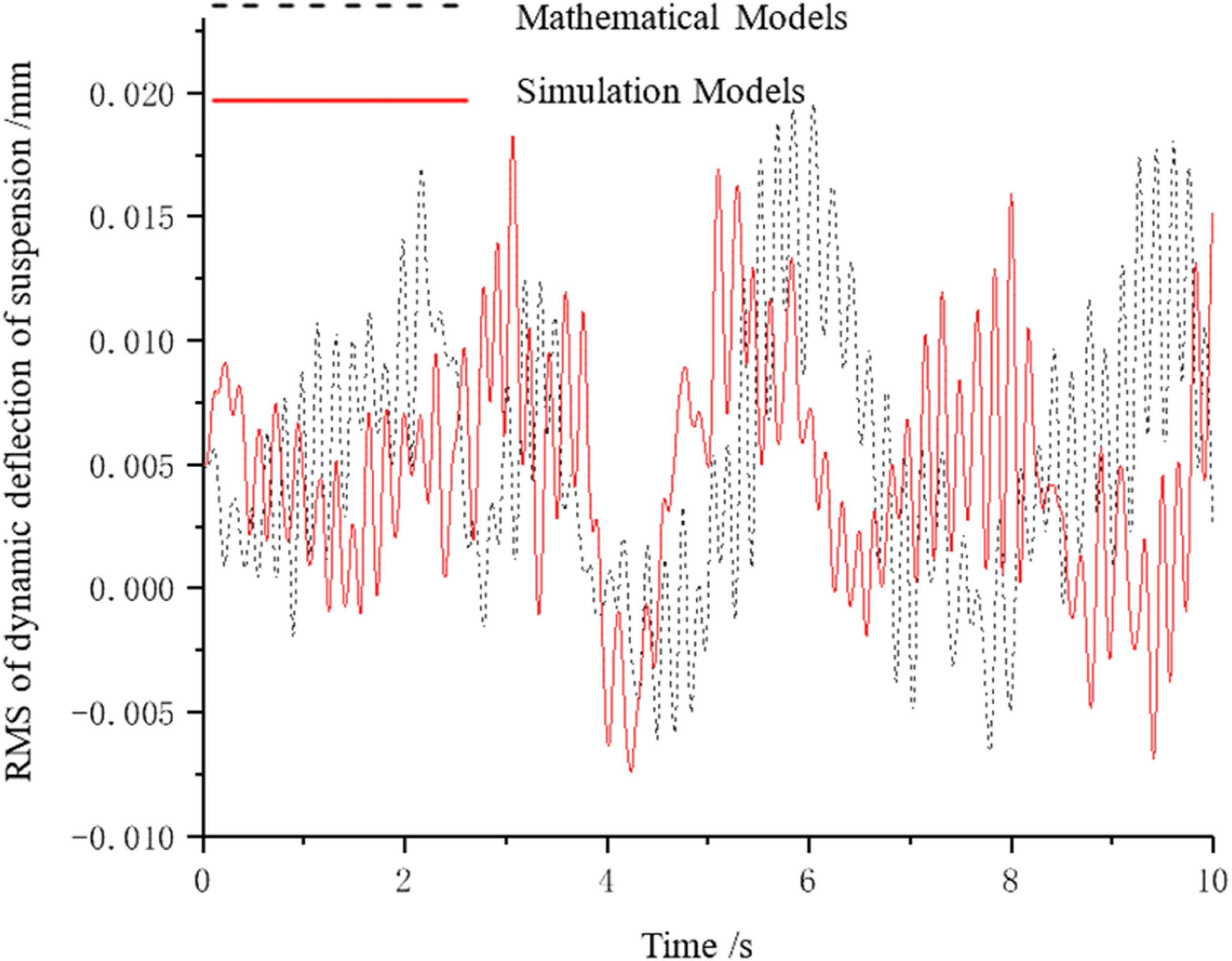
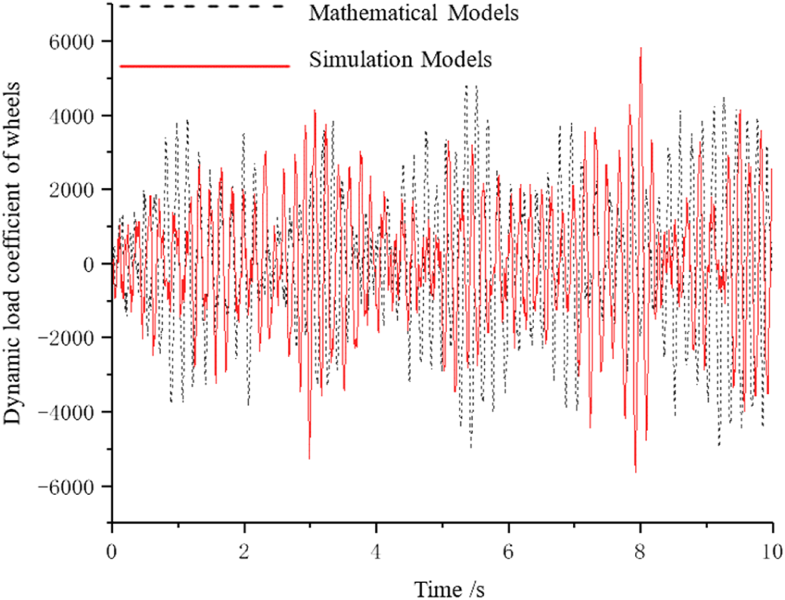
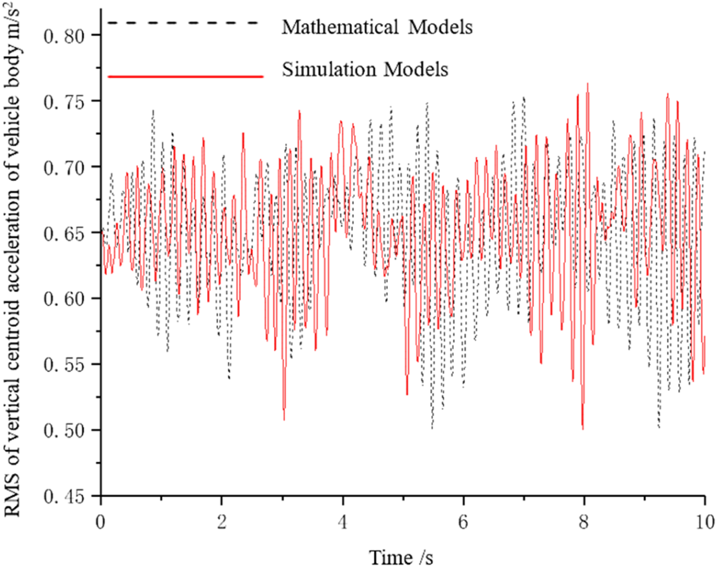
As shown in Figure 8 – 10, the mathematical model of 1/4 vehicle suspension system is in good agreement with the vehicle vibration response results of the co-simulation model, which proves the rationality and accuracy of the simulation model.
Vibration response analysis of 1/4 vehicle co-Simulation under harmonic excitation
The maximum displacement and maximum acceleration of the body are important indicators to measure comfort. The maximum displacement and maximum acceleration of the body under different excitation frequencies ωr are analyzed, taking three throttle orifice cross-sectional area ratios of β = 3, β = 1, and β = 1/3. The results are shown in Figures 11 and 12. As shown in Figure 11, in the frequency range of 0 ∼ 15 rad/s, the effects of the three schemes on the maximum displacement of the body show the same trend. In terms of general trends, in the frequency range of 0 ∼ 100 rad/s, β = 3 has less influence on the maximum displacement of the vehicle body than β = 1/3. Influence of bidirectional ratio on maximum displacement at different frequencies. Influence of bidirectional ratio on maximum acceleration at different frequencies.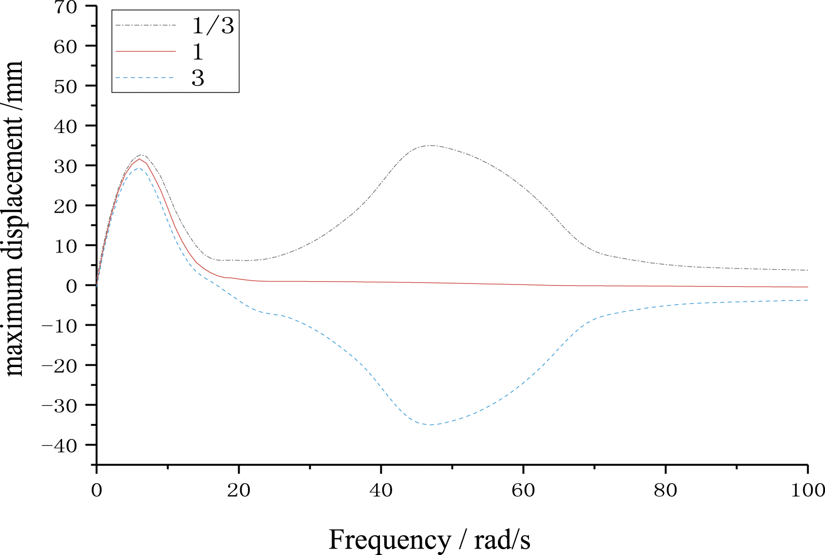
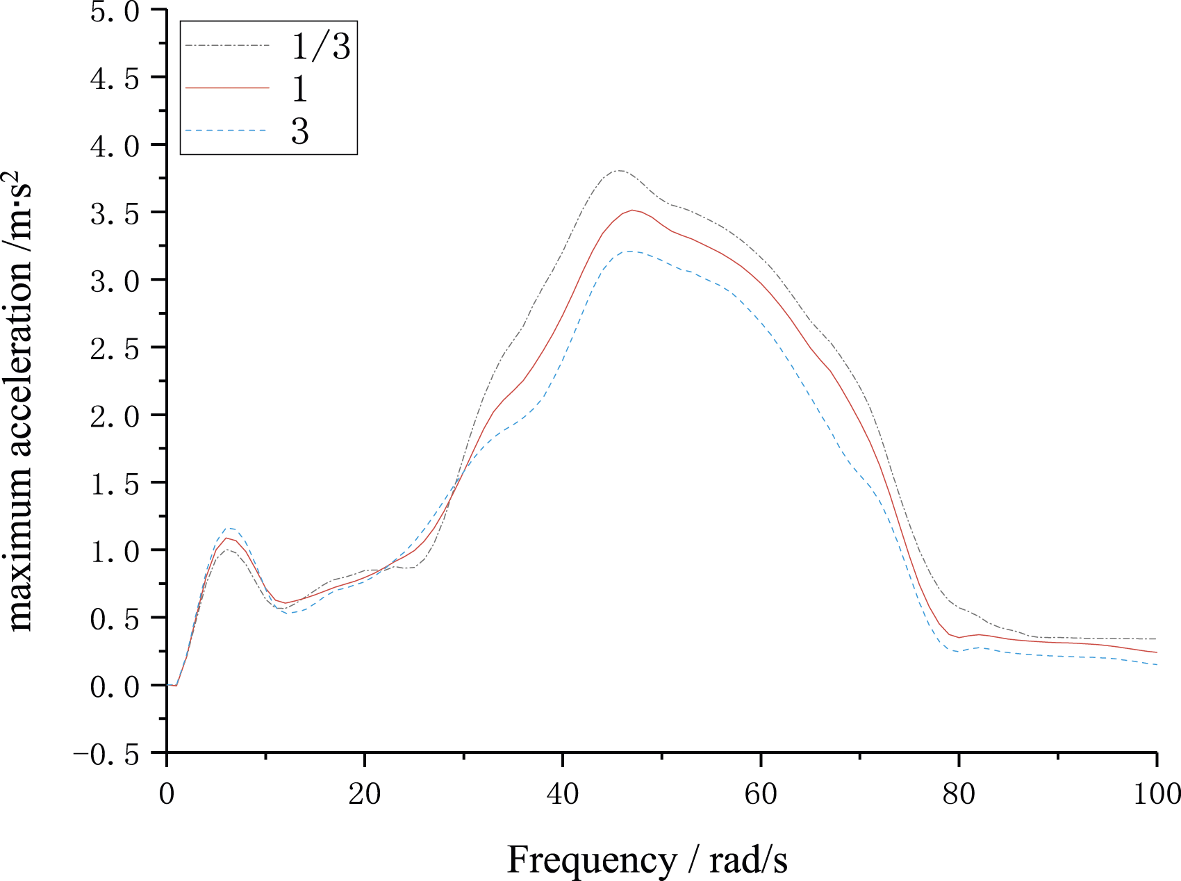
The low-frequency part of Figure 12 is locally amplified to obtain Figure 13, as shown below. Bidirectional ratio comparison curve of body acceleration approaching the first peak.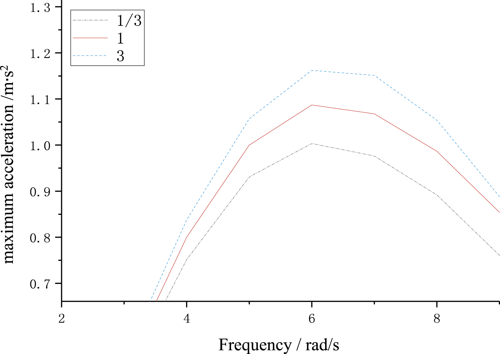
As shown in Figure 13, near ωr = 6 rad/s, the β = 1/3 scheme shows a lower body vibration acceleration than the β = 3 scheme. Compared with the β = 1 scheme, the body vibration acceleration of the β = 1/3 scheme is reduced by 14.31%. Compared with the β = 1 scheme, the body vibration acceleration of the β = 3 scheme is increased by 6.63%. Compared with the β = 3 scheme, the β = 1/3 scheme is reduced by 14.31%. The results show that the damping performance of the vehicle is better when the cross-sectional area ratio of the orifice of the hydraulic shock absorber is less than one under low-speed conditions.
The high-frequency part of Figure 12 is partially enlarged to obtain Figure 14, as shown below. Comparison curve of body acceleration approaching the second resonance peak.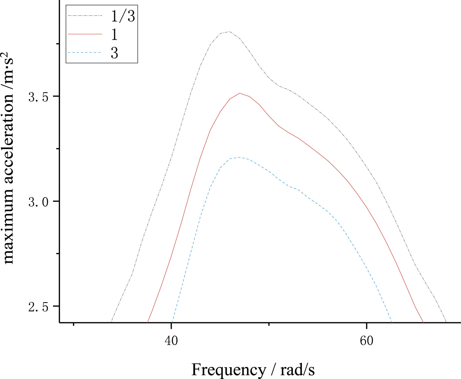
Figure 14 shows near ωr = 46 rad/s; the β = 3 scheme shows a lower body vibration acceleration than the β = 1/3 scheme. Compared with the β = 1 scheme, the body vibration acceleration of the β = 3 scheme is reduced by 8.17%. Compared with the β = 1 scheme, the body vibration acceleration of the β = 1/3 scheme is increased by 8.44%. Compared with the β = 1/3 scheme, the β = 3 scheme is reduced by 16.61%. The results show that the damping performance of the vehicle is better when the cross-sectional area ratio of the orifice of the hydraulic shock absorber is greater than one under high-speed working conditions, which is consistent with the value of the asymmetric damping ratio 2 ∼ 4 in the experience. 23
Vehicle co-Simulation
Establishment of vehicle co-Simulation model
The tractor model was built using Solidworks 3D modeling software and imported into Recurdyn dynamics software for simulation analysis. The model, as shown in Figure 15, has a total of 162 degrees of freedom and can realistically reflect the vehicle's vibration characteristics. In the suspension system of the model, the hydraulic shock absorber was modeled using AMESim hydraulic software and co-simulated with the Recurdyn dynamics model.24–27 Dynamics tractor model of Recurdyn.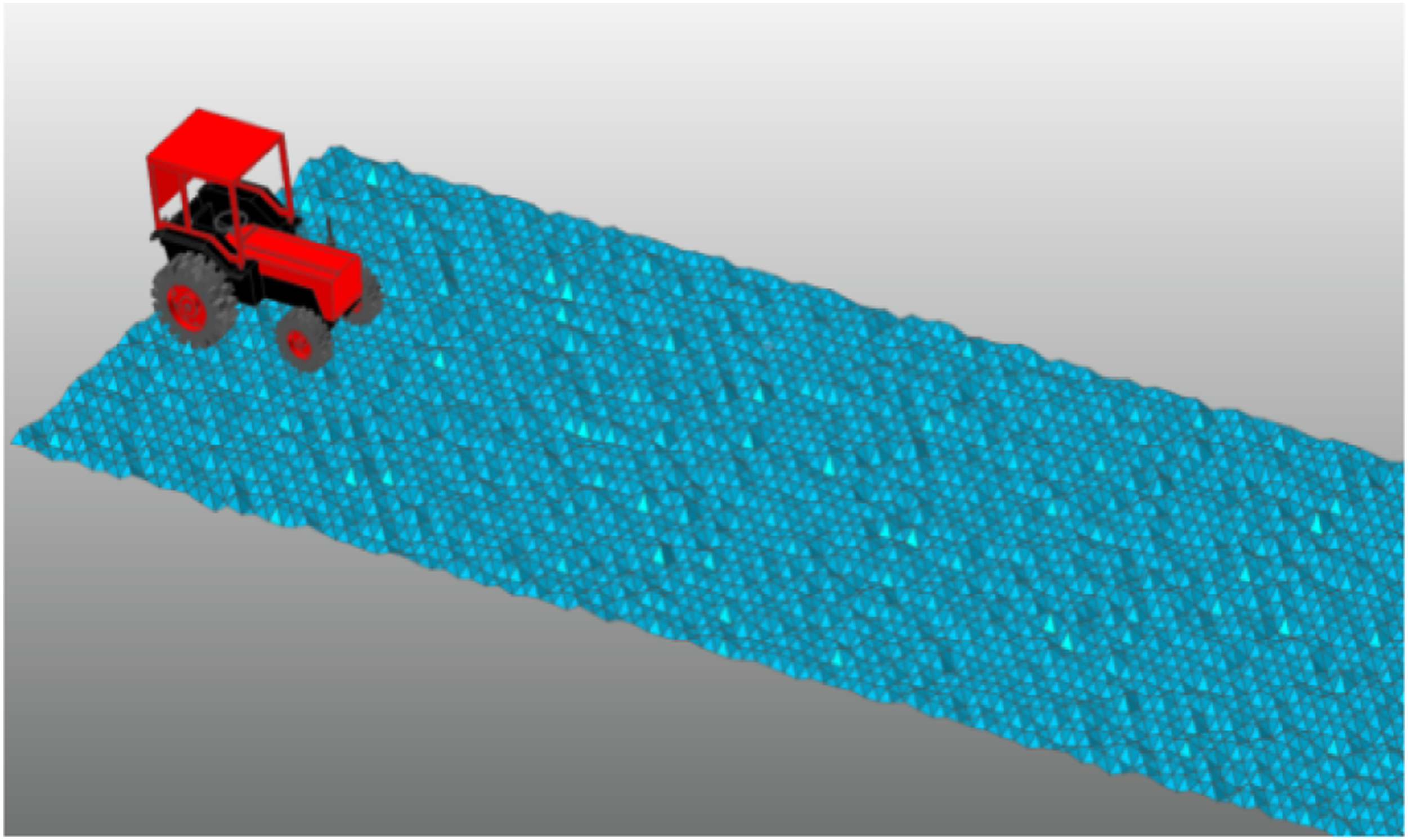
The accuracy of the model should be verified after its establishment, and this paper adopts the calibration method that compares the model’s vertical vibration intrinsic frequency with the empirical value.
28
The established model is placed at the center of mass 400 mm from the ground, and the free-fall simulation is set up. The static analysis of the model is carried out, and the signal is converted to a frequency domain signal. The results are obtained as shown in Figures 16 and 17. Acceleration response curve of vehicle body vertical vibration. Frequency domain curve of body vertical vibration acceleration.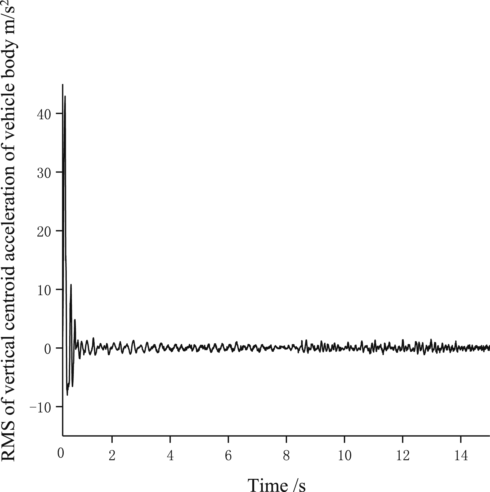
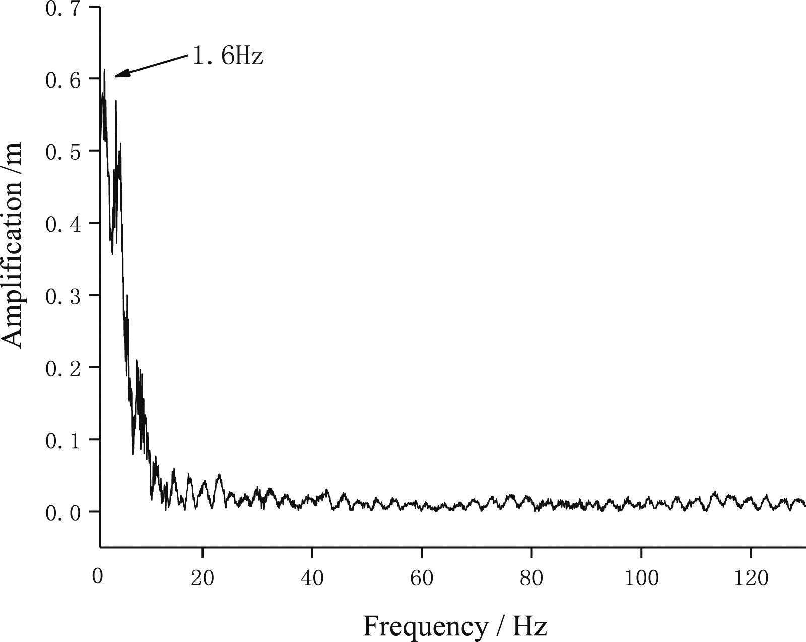
As shown in Figure s 16 and17, the model has a significant amplitude after contacting the ground and gradually reduces to 0. The intrinsic frequency of the vertical vibration of the center of mass of the body is about 1.6 Hz, which is closer to the actual empirical calculation of 1.5 Hz, and it can be proved that the model is reasonable.
The combined simulation model of Recurdyn and AMESim is shown in Figure 18, where the AMESim hydraulic shock absorber model does not consider the deformation of the shock absorber internal structure caused by changes in oil hydraulic pressure and temperature.
29
AMESim and Recurdyn co-simulation model.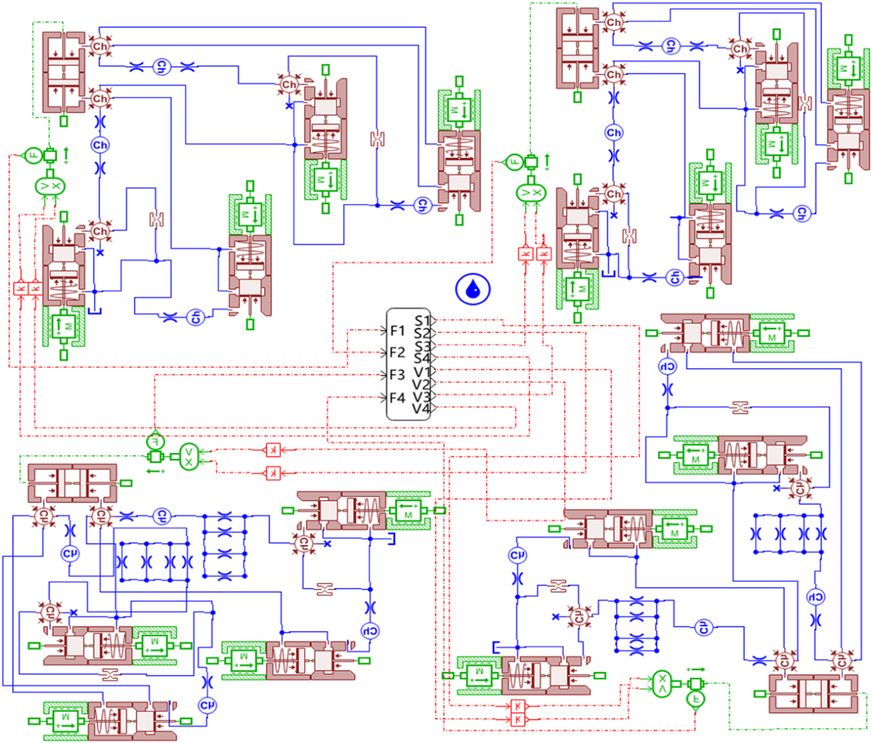
Influence of orifices on vehicle suspension performance
Based on the three orifice area schemes mentioned above, a comparative analysis was conducted using the Recurdyn and AMESim co-simulation models. The vibration responses of the vehicle's vertical acceleration of the center of mass, suspension deflection root-mean-square (RMS) value, and tire dynamic load coefficient under the Class A road spectrum at different speeds are shown in Figures 5 – 7, respectively.
As shown in Figure 19, when the vehicle speed is low (less than 10 km/h), the RMS value of the vertical acceleration of the center of mass is the smallest for the β=1/3 (scheme 3), followed by β=1 (scheme 2), and β=3 (scheme 1) is the largest. However, after the vehicle speed exceeds 15 km/h, the situation is reversed, and the β=3 scheme results in the smallest RMS value of the vertical acceleration of the center of mass, while the β=1/3 scheme leads to the largest value. Influence of cross-sectional area ratio of the throttle orifice on RMS vertical acceleration of vehicle body at different speeds.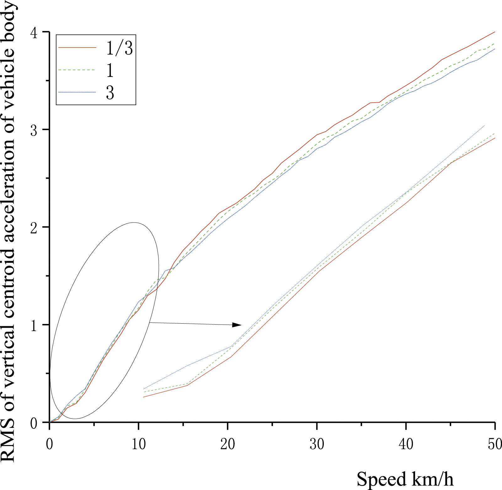
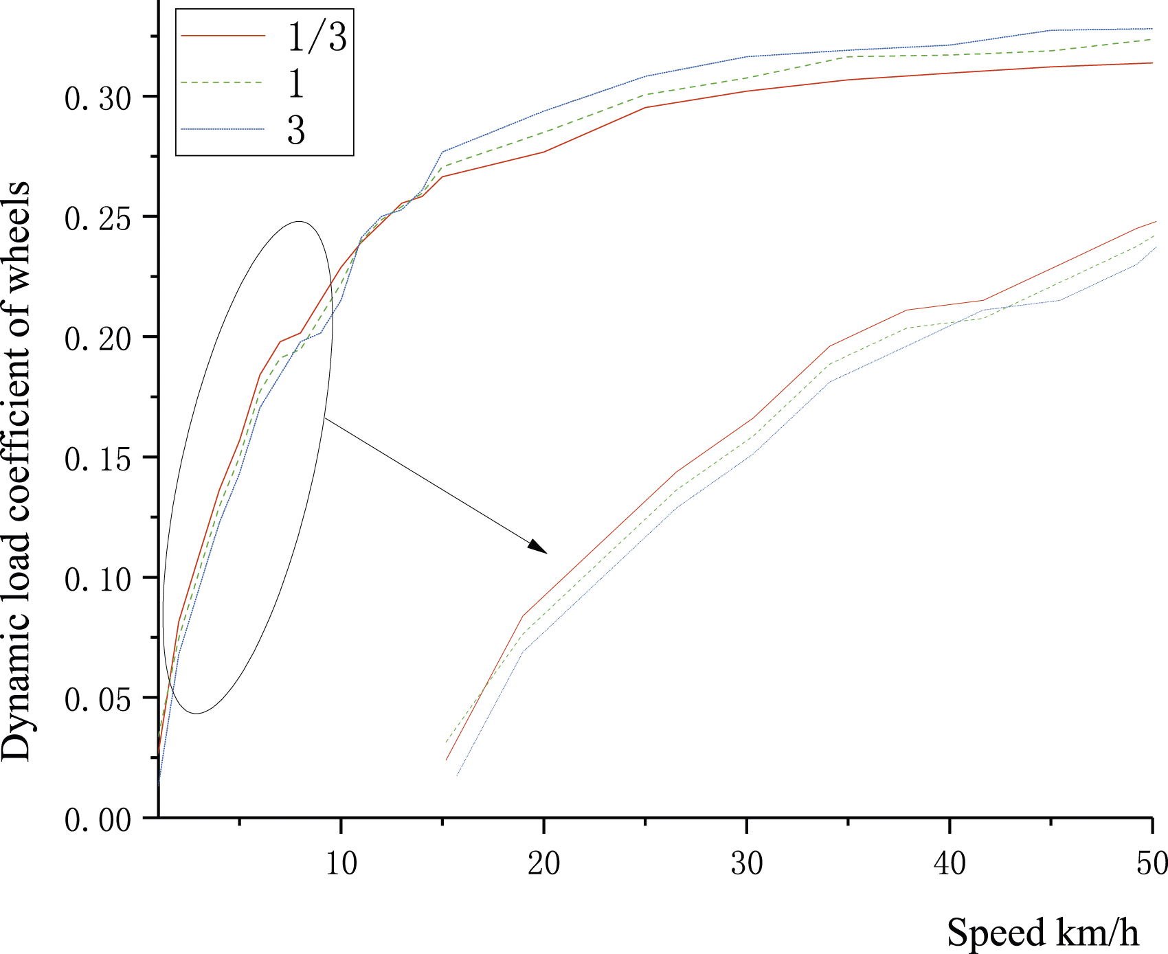
As seen in Figures 20 and 21, when the vehicle speed is low, the suspension deflection RMS value and the tire dynamic load coefficient are both the smallest for the β=3 scheme and the largest for the β=1/3 scheme. However, after the vehicle speed exceeds a certain threshold, the opposite is true, with the β=1/3 scheme resulting in the smallest values and the β=3 scheme leading to the largest values. Influence of cross-sectional area ratio of the throttle orifice on RMS of dynamic deflection of suspension at different speeds. Influence of cross-sectional area ratio of the throttle orifice on dynamic load coefficient of wheels at different speeds.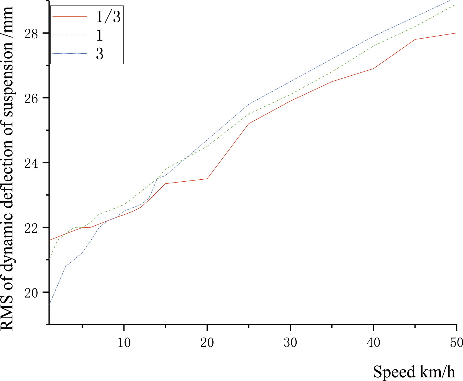
Selection of throttle orifice hole area ratio
1. Low-speed working tractors
Since the optimization of damping coefficient for hydraulic shock absorbers is relatively unified,
30
this paper selects the cross-sectional area ratio of the throttle orifice under the determined damping coefficient. Figure 22 shows the relationship between the cross-sectional area ratio of the throttle orifice (0<β<1) of this type of tractor on a D-class road surface at 5 km/h and the root mean square values of the vertical acceleration of the vehicle body and suspension deflection. The relationship between the cross-sectional area ratio of the throttle orifice and the vibration response of the vehicle at the speed of 5 km/h.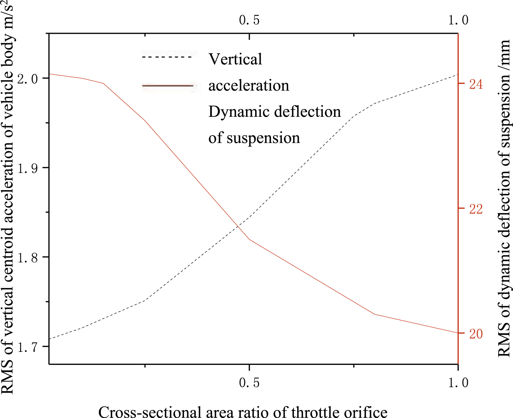
The suspension limit travel of the tractor is 70 mm, and the root-mean-square value of the suspension deflection is set to one-third of the limit travel, i.e., 23 mm, at which the probability of suspension breakdown is less than 0.135%.
31
In Figure 8, each cross-sectional area ratio of the throttle orifice (β) corresponds to a unique vertical acceleration of the vehicle's center of gravity and a root-mean-square value of the suspension deflection. Therefore, with a suspension deflection root-mean-square value of 23 mm, the corresponding β can be obtained as 0.32. At this point, the root-mean-square value of the vertical acceleration of the vehicle's center of gravity is minimal, at 1.78 m/s2, and the tire dynamic load factor is 0.25, meeting the requirement of not exceeding 1/3 and having good tire grounding [16]. 2. Height-speed working tractors
Assuming this type of tractor as a vehicle driving at high speed and selecting the cross-sectional area ratio of the throttle orifice, the relationship between the cross-sectional area ratio of the throttle orifice (1 < β < 25) and the root-mean-square value of the vertical acceleration of the vehicle's center of gravity and the root-mean-square value of the suspension deflection is obtained under the condition of A-level pavement and a speed of 50 km/h.
Assuming a suspension limit travel of 85 mm, the suspension deflection root-mean-square value is set to 28 mm. The same method is used to select the cross-sectional area ratio of the throttle orifice as that for the low-speed working tractor described above. The corresponding cross-sectional area ratio of the throttle orifice is obtained as 3.1 in Figure 23. At this point, the root-mean-square value of the vertical acceleration of the vehicle's center of gravity is minimal, at 3.32 m/s2, and the tire dynamic load factor is 0.32, not exceeding 1/3. The relationship between cross-sectional area ratio of the throttle orifice and vehicle vibration response at vehicle speed of 50 km/h.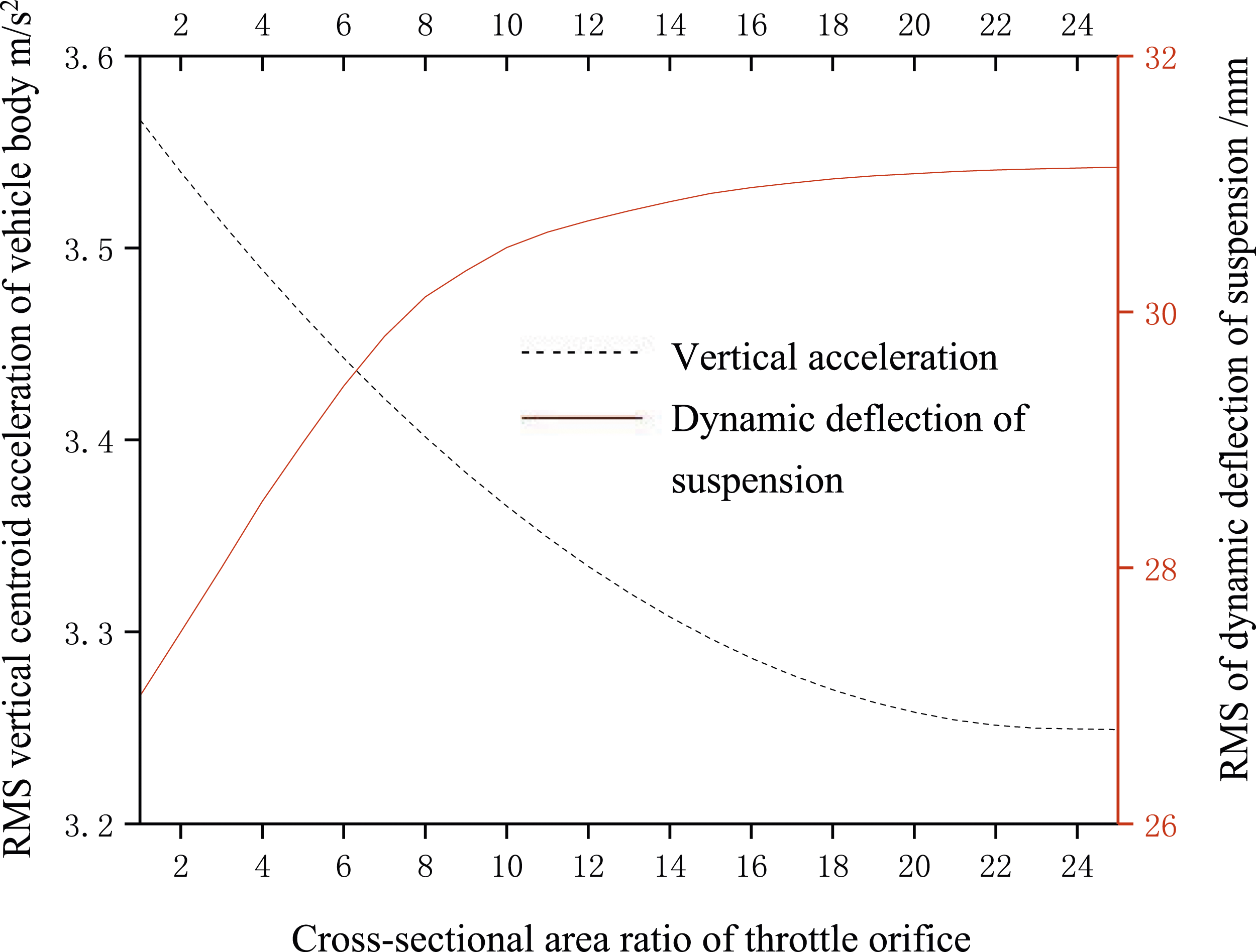
Conclusion
1. In this study, a combined approach of mechanical and hydraulic systems was employed, which, compared to linearizing the nonlinear damping forces using a purely mathematical model, enhanced calculation accuracy to a certain extent. Utilizing the kriging model for approximating the AMESim hydraulic shock absorber model parameters improved calculation speed. The multi-island genetic algorithm and the gradient descent algorithm are used to obtain three schemes with equivalent damping coefficients. Effectively enhancing the precision. This method also provides reference significance for the design of structural parameters for other vehicle shock absorbers. 2. Under harmonic excitation, the results of the quarter-vehicle simulation model for the vehicle indicated that near the frequency ωr = 6 rad/s, with β=1/3, the vehicle's body vibration acceleration was approximately 0.98 m/s2, lower than the values for the other two scenarios. However, near the frequency ωr = 46 rad/s, with β=3, the vehicle's body vibration acceleration was approximately 3.23 m/s2, also lower than the values for the other two scenarios. 3. The simulation model of the entire vehicle analyzed the body center acceleration, suspension deflection, and tire dynamic load for the three scenarios with β = 3, β = 1, and β = 1/3 under an A-level road spectrum over the range of 0 to 50 km/h vehicle speeds. In low-speed conditions (vehicle speed <10 km/h), β = 1/3 resulted in the minimum body center acceleration, with relatively larger values for suspension deflection and tire dynamic load. Conversely, in medium to high-speed conditions (vehicle speed >15 km/h), β=3, produced the same results. For low-speed conditions (5 km/h) under a D-level road spectrum, an analysis of body center acceleration and suspension deflection within the suspension travel limit revealed that β = 0.32 resulted in the minimum body center acceleration (1.78 m/s2). In high-speed conditions (50 km/h) under an A-level road spectrum, β = 3 yielded the minimum body center acceleration (3.52 m/s2).
The research results of this paper indicate that for low-speed conditions, the throttle orifice area ratio β of the hydraulic shock absorber should be kept as small as possible, preferably less than 1, to reduce body vibration acceleration and enhance comfort. However, for high-speed conditions, it is preferable to have greater than 1. These conclusions are drawn based on body acceleration and suspension deflection indicators under typical conditions, and further research is needed in the future to explore additional operating conditions and comfort evaluation metrics.
Footnotes
Declaration of conflicting interests
The author(s) declared no potential conflicts of interest with respect to the research, authorship, and/or publication of this article.
Funding
The author(s) disclosed receipt of the following financial support for the research, authorship, and/or publication of this article: This work was supported by National Natural Science Foundation of China (Item No. 52272401), Basic Research Project of Shanxi Province, China. (Item No. 202203021211185), and Graduate Education Innovation Project of Taiyuan University of Science and Technology. (Item No. SY2022055).