
Abstract
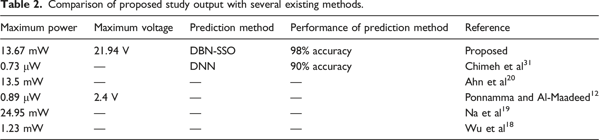
This work fabricated the piezoelectrical material using PMMA (polymethyl methacrylate) and Ce-doped ZnO nano-powders. The study was conducted to validate the piezoelectric performance of the proposed material and its suitability for the cantilever structure. The PMMA/Ce-ZnO makes the cantilever structure more flexible and performs better. The frequency response is applied to the beam using an electrical circuit to analyze the power and voltage output. The acceleration is given to the cantilever beams to analyze their resonant frequencies. The change in resonant frequencies results in a high voltage and power output. The resistive loads are used in the circuit to find the electrical load. The frequency response is analyzed in three different inner (18 mm, 20 mm, 22 mm) and outer (23 mm, 25mm, 27 mm) active layer lengths of beams. As a result, the maximum voltage of 21.94 V with 13.67 mW power and 2.9 mA current is obtained at a resonant frequency of 51.06 Hz and 1g acceleration amplitude, which are approximately 42%, 45% and 15% higher voltage, power and current obtained from the lowest performer of proposed piezoelectric cantilevers. The experiment results are validated using the hybrid DBN-SSO (Deep Belief Network based Salp Swarm Optimization) machine learning technique. The proposed DBN-SSO achieved 0.9998 and 0.9966 regression coefficients for voltage and power outputs, thus proving the fitness of predicted results with the experiments. As per findings, a 27 mm inner and 18 mm outer active layer based energy harvesting system is suggested as a suitable energy source where ever 10-12 mW power, 2.5-2.9 mA current and 20-21.94 V voltage are applicable.
Keywords
Introduction
In less consumption-based electronic components, sustained electricity is achieved through recent energy harvesting approaches. The commonly utilized energy harvesting approaches are mostly based on electromagnetic, piezoelectric, electrostatic principles, etc. 1 Due to the capability of maximum electromechanical efficiency and simple structural nature, recent researchers have familiarly used certain piezoelectric energy harvesters. This harvesting technique applies to radio frequencies, triboelectric, photovoltaic, thermoelectric technology, etc. 2 Piezoelectric materials are one of the basic materials utilized for smart structure applications due to the immediate and converse piezoelectric effects that allow them to be used as actuators and sensors. Besides, such materials are commonly utilized in intelligent structures, sensing devices, vibration control devices, and various other fields. The piezoelectric materials often respond to temperature variations in variable temperature conditions.3,4 Therefore, several researchers have been involved in developing different piezoelectric-based nanogenerators using different techniques.
Several researchers were highly involved in developing different piezoelectric-based nanogenerators using different techniques. Song et al. 5 developed a textile-based piezoelectric nanogenerator and tribological units for mechanical energy harvesting. The doctor blading method optimized polydimethylsiloxane (PDMS) multi-walled carbon nanotube and graphite nanoparticle based flexible composite film. A new model for a hybrid nanogenerator was introduced, and promising results were obtained from the research. Zhou et al. 6 developed a carbon coating modulation-based piezoceramic nanoparticles/PDMS composites for energy harvesting. The piezoelectric property was enhanced by poling process and pictured by Lewis diffusion theory. Lin et al. 7 developed a high-frequency vibration sensor for monitoring structural health. The presented novel self-powered sensor-based nanogenerator has high vibration sensing with broad frequency response. The sensor having the next-generation vibration sensor feature applies to detecting fractures in rail tracks, monitoring automobile engines, etc. Different inorganic materials, namely BaTiO3, ZnO, and PZT, are commonly used in this aspect. Besides, organic materials such as polytetrafluoroethylene (PTFE), polyvinylidene fluoride (PVDF), etc., are also contributing to the piezoelectric-based energy harvesting applications. 8 PMMA and PVDF are outstanding polymers due to their convenient processing, lighter weight, flexibility, and stability under maximum electrical effect.9,10
In the view of inorganic nanoparticles, ZnO, BaTiO3 based Nano generators are majorly reported in different kinds of literature. ZnO is widely utilized in LED, laser, and various electronic device applications because of its enhanced binding energy. 11 Besides, BaTiO3 possesses better ferroelectric properties. Ponnamma and Al-Maadeed 12 proposed flexible nano-composite films which use inorganic BaTiO3 as filler material. The author observed enhanced polymer properties on the energy harvester with a maximum 2.4V output voltage. Also, several existing research works incorporate organic and inorganic materials for energy harvesters. Signore et al. 13 analyzed the thermal, dynamic, mechanical, and photoelectric response of incurable Nano cellulose/AlN acrylic flexible films. X-ray Diffraction (XRD) and Scanning Electron Microscopic (SEM) analysis were used to evaluate the thermal and mechanical properties of the proposed piezoelectric material. Besides, root mean square open circuit voltage was used to evaluate the piezoelectric behaviour. The ZnO nanostructure into the AlN improves the photoelectric response and output voltage. Reghat et al. 14 used graphene for coating in glass fiber composites to enable strain monitoring. The property analysis showed an increase in normalized resistance but showed a decrease in flexural strength and tensile strength. Zhang et al. 15 developed a Graphene Oxide (GO) and Lead Zirconate Titanate particles (PZT) reinforced Poly (vinylidene fluoride) (PVDF) composite. The composite was fabricated with different proportion rates of GO particles assisted with the extrusion casting process. By varying the polarization field effect, better electromechanical properties are recorded. The highly stiffened graphene reinforced PVDF piezoelectric composite was developed by Mao and Zhang 16 based on a vibratory motion under linear and non-linear conditions.
Several existing types of research focused on the cantilever-based piezoelectric harvester, which provides maximum output due to its hinged end. In this type, an external disturbance is performed at the end of the beam, assisted with mass and other excitations such as rotational, vibratory, magnetic-based systems, etc.17,18 The analysis of a magnetically coupled bimorph cantilever beam connected with a permanent one has been conducted by Na et al. 19 The increased voltage range was observed due to the increased wind speed from 2.5 m/s to 6.5 m/s, and the maximum power of 24.95 mW was achieved from that research. Ahn et al. 20 have fabricated a cantilever-based energy harvester connected to the ball (tip mass). The vibration amplitude of the ball analyzes the output behaviours. Besides, at the resonant frequency of 15 Hz, 13.5 mW was observed as the maximum power. By enhancing the applications of the cantilever, a bistable L-shaped beam was developed by Yao et al. 21 The author proved that the proposed model achieves better power output and stiffness hardening. The rotational excitation is usually achieved by piezoelectric DC motors and can result in a larger amplitude range and sometimes cause damage to the piezoelectric materials. 22
During magnet-based excitation, the piezoelectric material is deformed by the magnetic force generated by the stator and rotor. But in some instances, the material gets highly deformed due to the effect of the higher maximum reaction force magnetic field. 23 Rui et al. 24 developed a rotational piezoelectric energy harvester with limiters and analyzed it for application. The harvesters expect a high energy harvest, but in this model, the energy harvesting is limited, and life is improved in the long-term perspective. The study also found that stiffness had a minimal effect on limiting effects. The experimental analysis has shown no change in output. Rui et al. 25 developed a new design for a piezoelectric harvester. The author introduced theoretical models for the frequency adjustment relationship, where the tuning process changes the length between the center of rotation and mass.
Besides, due to the advanced technologies in engineering experiment prediction, simulation and optimization of solutions, Chen and Bedekar 26 modelled a piezoelectric broadband energy harvester using COMSOL multi-physics software. The simulation was carried out on three different geometries of piezoelectric bimorph beams. Based on the result, the author concluded such simulation modelling tools can reduce the experimental cost and material wastage while enhancing the performance of energy harvester devices. Similarly, using a finite element tool, Nabavi and Zhang 27 numerically designed certain piezoelectric micro energy harvesters by changing their width and length. The author also implemented a Genetic Algorithm (GA) method to optimize the geometry of the designed piezoelectric material. By comparing the results with several existing simulation models, the GA optimized the results accurately at less run time than the existing methods. In another work, Bagheri et al. 28 have proved that applying a well-trained Artificial Neural Network (ANN) and GA together can predict the output voltage of a piezoelectric cantilever energy harvester and optimize its geometry. The developed ANN-GA model achieved a significant regression coefficient over 0.9 for both the training and testing stages and showed better fitness values while optimizing output voltage and efficiency of the energy harvester unit as well.
However, there is a need for adequate amplitude for efficient energy harvesters. 29 To resolve these issues, rotary and gravity-based techniques are employed in this work for better piezoelectric performances. Also, the validation of experimental outcomes using neural networks in various similar research works to prove the effectiveness of experimentation 30 motivated to use of the machine learning method in the validation of study outcomes. Based on the literature, Chimeh et al. 31 achieved better optimization results from a deep learning method called Deep Neural Network (DNN) coupled GA optimizer. In this manner, the present study adapted Deep Belief Network (DBN) from Wang et al. 32 as a deep learning algorithm and Salp Swarm Optimization (SSO) from Mirza et al. 33 as an optimization algorithm due to their convincing performances while solving similar engineering issues. Furthermore, this research work aims to improve the electrical properties of piezoelectrics by doping them with nanoparticles. In this regard, a new piezoelectric bimorph cantilever beam is developed with a piezoelectric composite and a thin acryl sheet as an inner active layer and outer elastic layer. Therefore, the piezoelectric excitation is provided by applying mass gravity and DC Motor. So, both rotational and gravitational effect is performed in a piezoelectric energy harvesting system. Also, the tip mass balances the higher amplitude generated due to rotation speed. However, not sufficient works have been conducted to develop the piezoelectric bimorph cantilever beam with various layers, as presented in this study. By changing the length with the application of tip mass, the bending moment is produced in the cantilever structure; thereby, power output is achieved during this study. The accuracy of this experiment is also verified by validating with the proposed Deep Belief Network-Salp Swarm Optimization (DBN-SSO).
The research work is organized in the accompanying ways that the proposed methodology and experimental strategies are specified in section 2. The research outcomes and discussions are elaborated in section 3. The last section 4 contains the conclusion and future scope of current research work.
Materials and Methods
Theoretical background of this study
The piezoelectric cantilever energy harvester system with magnetic tip mass at its free end is planned to construct in this study. The piezoelectric cantilever structure is allowed to vibration, which is caused by attractive and repulsive magnetic force excited by another magnet fixed on the rotating disc of the DC motor. Due to this vibration produced in the piezoelectric cantilever beam, the strain is developed on the piezoelectric material at its fixed end; thereby, a voltage difference is accumulated in the energy harvester. More voltage difference and power generation can be obtained from the proposed piezoelectric cantilever energy harvester when subjected to larger strain and faster strain change rate. 18 Furthermore, this study attempts to improve the rate of strain change and the amount of accumulated strain on the cantilever by changing the length of the inner and outer active layers. In addition, a novel piezoelectric composite material will also be investigated, which can help improve the output power and voltage generation of the proposed energy harvester.
Proposed method
The piezoelectric composite is used as an inner active material, and the acryl sheet is the outer active material. The piezoelectric composite is developed using a casting process by PVDF, PMMA, BaTiO3, and ZnO powders. The mass ratio of BaTiO3 and ZnO Nanoparticles is 1:1. In this work, experimentation is carried out by applying a cantilever beam of different lengths, such as 27mm, 25mm, and 23mm. A thin Acryl sheet is used as an outer active layer for piezoelectric composite cantilever beam structure because these acrylic sheets are thin and transparent plastic sheets, easy to bond by adhesive force. The length of the Acryl sheet is kept smaller than the cantilever beam in order to attach a tip mass. The attached tip mass mainly generates an enhanced peak to peak voltage range due to vibration and broadened frequency bandwidth. Therefore, the lengths of the Acryl sheet are 22mm, 20mm, and 18mm. The energy outcomes from the proposed piezoelectric composite are measured by varying the excitation frequency range 0Hz to 200Hz at a different motor speeds of 500 r/min, 1000 r/min, and 1500 r/min. Finally, the hybrid DBN-SSO approach is used to validate experimentally determined electrical results and verify the effectiveness of the results, as shown in Figure 1. Proposed flow of work.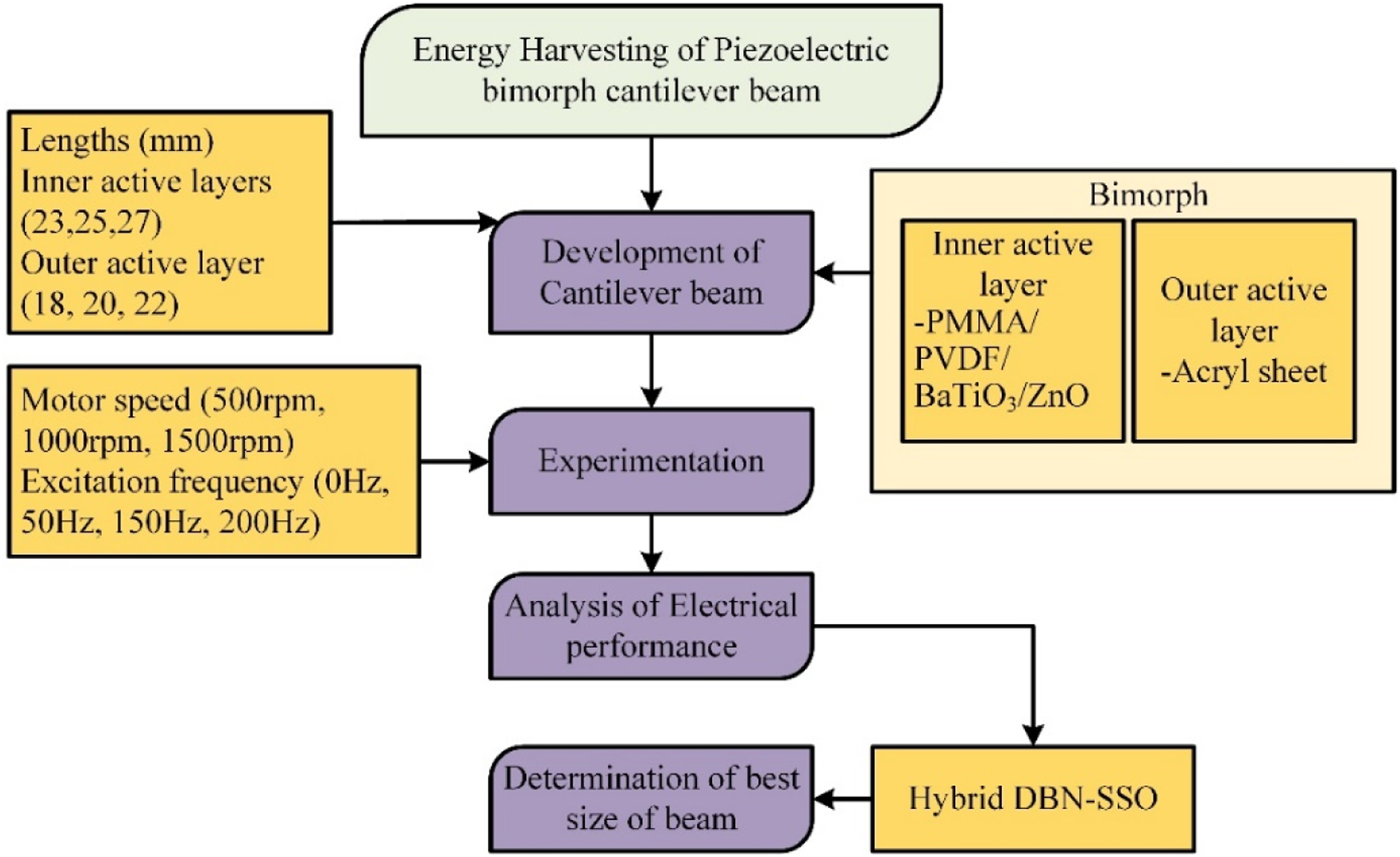
Experimental and testing procedures
Initially, entire powders are dispersed uniformly using the Dimethylformamide (DMF) solution with a powder to DMF mass ratio of 1:10. The uniform dispersion is achieved by magnetic stirring behaviour for 2 h at a constant temperature of 25°C. Finally, the sample suspension is achieved by continuously stirring for 45 min, maintaining 75°C. Then, the composite sheet is prepared by the doctor blade casting technique with a thickness of 45µm. The prepared composite is allowed for isostatic pressing under warm conditions for around 30 min at 60°C and 23 MPa. The developed composites (inner active layer) and acryl sheet (outer layers) are bonded using adhesive epoxy resin to develop the bimorph piezoelectric cantilever model. From Figure 2, the grey dots represent the dispersion of ZnO particles throughout the surface of the piezoelectric composite (PMMA/PVDF/ZnO/BaTiO3), whereas the reinforcement of BaTiO3 represents white shades. Micro craters are found in the SEM images of proposed piezoelectrics due to reinforcement of ZnO and BaTiO3 in PMMA/PVDF composite. However, this composite piezoelectric material could generate energy when subjected to a strain. Therefore, experiments are performed with a cantilever made of PMMA/PVDF/ZnO/BaTiO3 composite material. SEM image of prepared piezoelectric composites (PMMA/PVDF/ZnO/BaTiO3).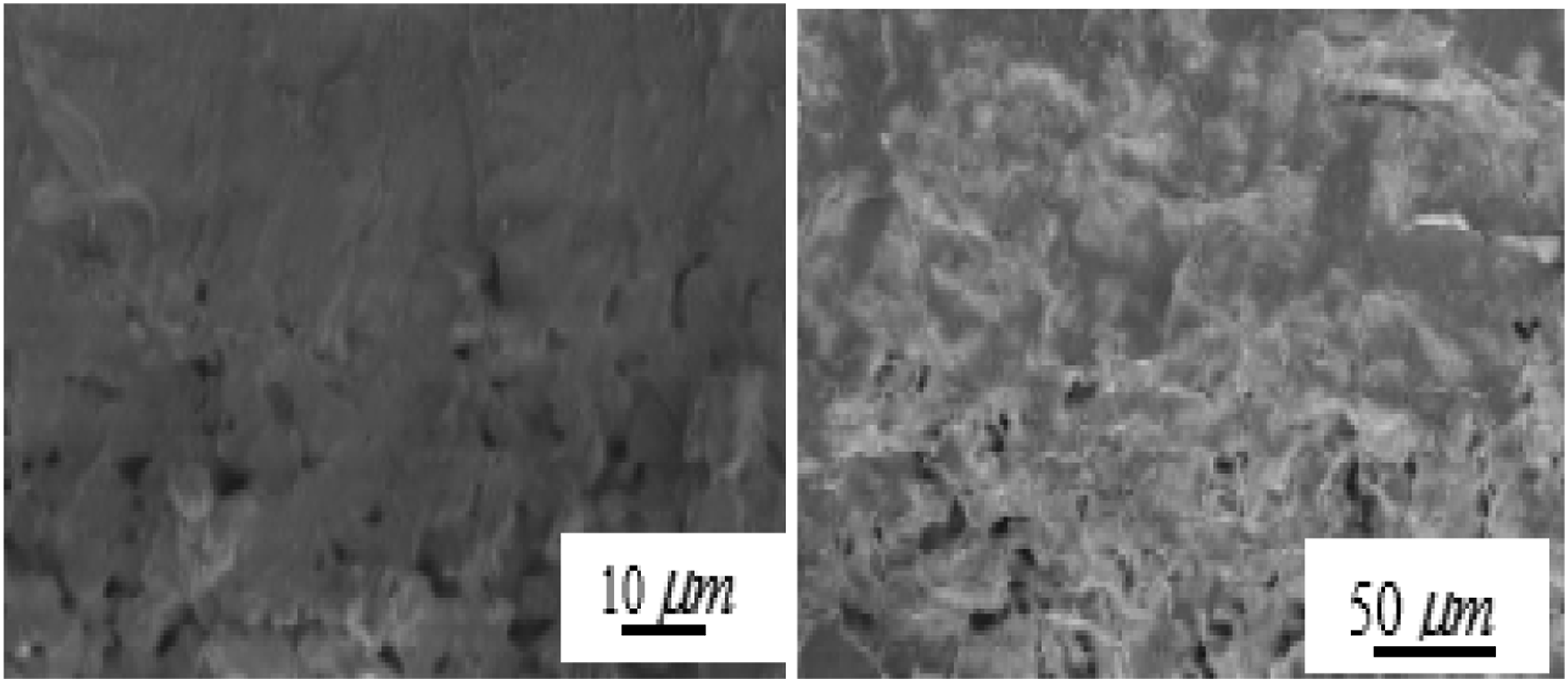
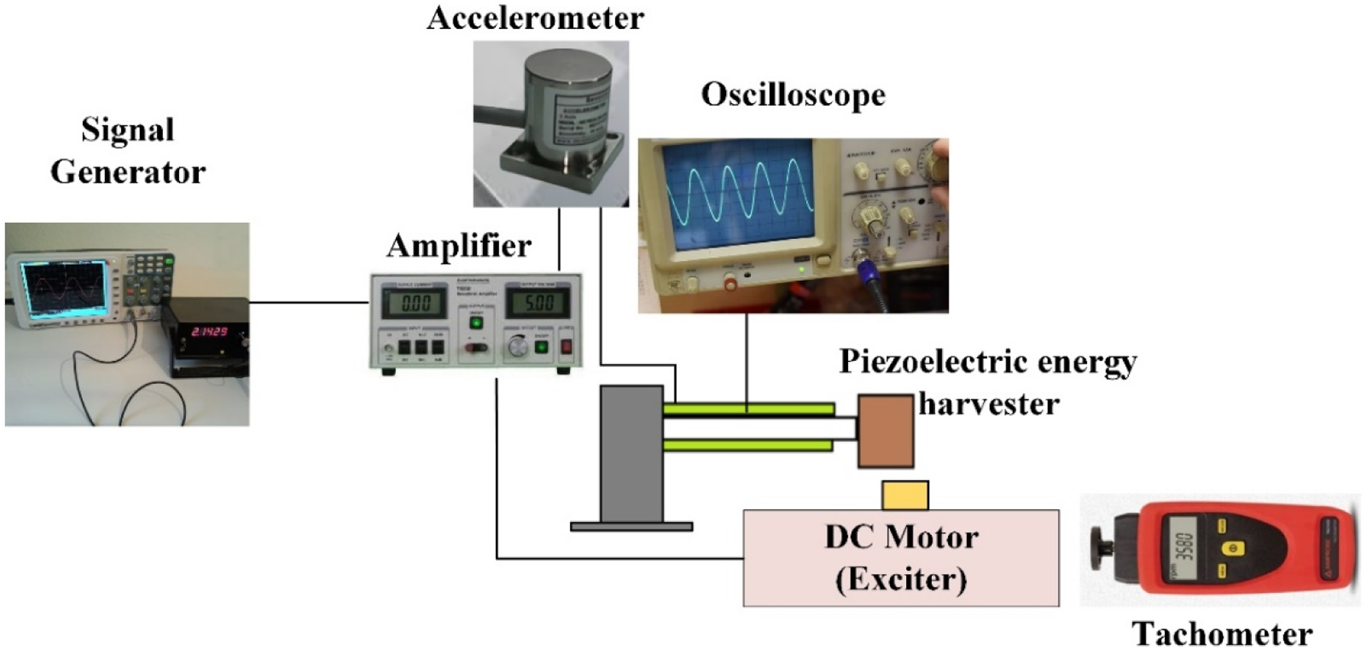
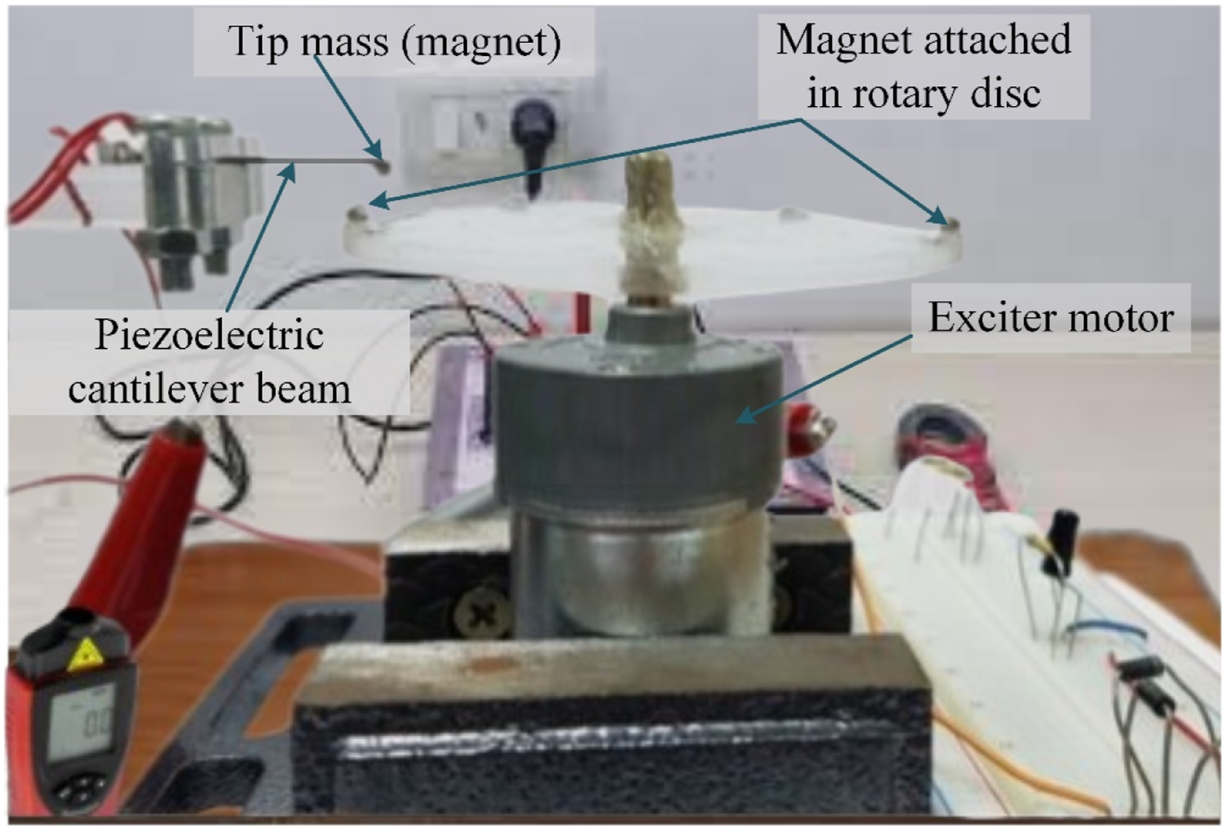
An open-circuit output voltage of the hybrid piezoelectric composite is measured using an Oscilloscope. The cantilever beam gets disturbed by the magnetic field induced by the rotary motion of a DC motor with an acrylic disc and magnets on its rotary pin. The rotational speed of the DC motor is measured through Tachometer in real time. The mass connected at the cantilever’s end also has magnetic behaviour to respond towards attractive and repulsive magnetic forces produced by motor rotation. The deformation of the proposed piezoelectric bimorph cantilever beam structure is represented in Figure 3. To avoid any direct contact or fusion between two magnets 1.5mm gap is maintained between the piezoelectric cantilever beam and acrylic disc after trial experiments. The layers’ width and thickness are 7.5mm and 0.2mm in the bimorph system. During the experiment, the composite-based piezoelectric cantilever harvester is connected to the fixture, and a vibration exciter is placed below the harvester system, as given in Figure 4. The power amplifier controls the beam’s vibration and receives the signals produced by the generator. In order to measure the vibrational acceleration of a cantilever beam, an accelerometer is connected at the fixed end of a cantilever structure. The piezoelectric cantilever energy harvester with magnetic rotary exciter used in this study is given in Figure 5. Positions of an excited and non-excited piezoelectric cantilever beam. Piezoelectric energy harvester layout. Piezoelectric cantilever beam and rotary exciter setup.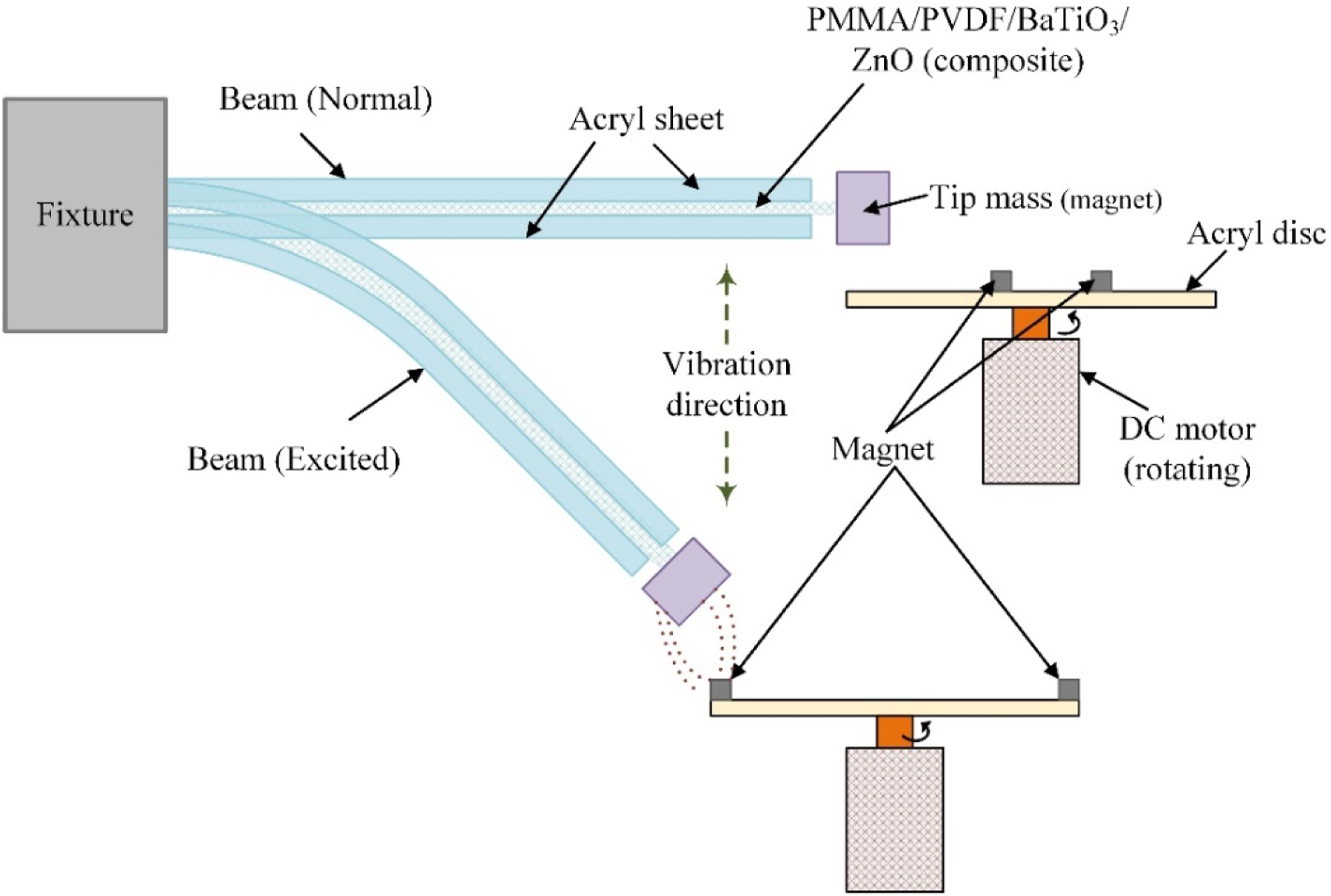
Deep belief network -salp swarm optimizer (DBN-SSO)
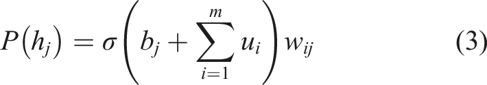
The deep learning technique based on the stack of restricted Boltzmann machines and the number of the output layer is defined as the deep belief network. RBM has several layers connected with other layers, but the connections do not link with each layer (Figure 6). The visible units in the layers are connected with the hidden units. Layout of DBN.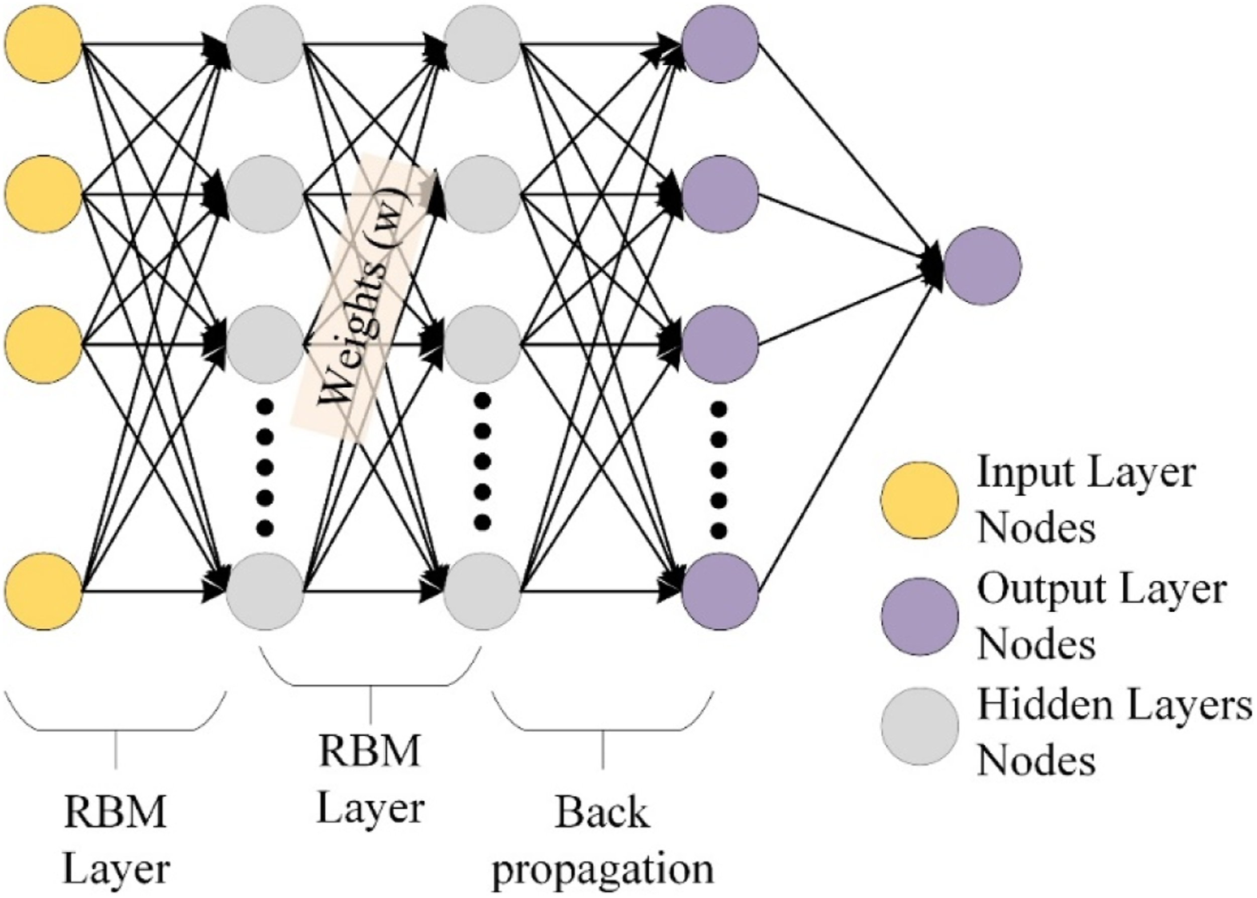
The multilayered RBM is considered the bottom layer of the DBN structure. In this, the visible layer is connected to the hidden layer. The trained output values obtained from the visible layer act as the hidden layer inputs.32,34
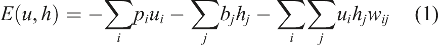
During the training stage, unsupervised learning is performed. The energy function of the visible and hidden layers are given as,
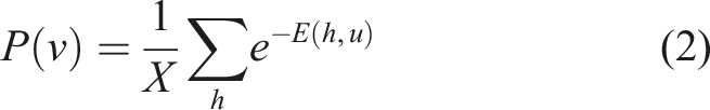
The probability function of the visible layer is,
In the hidden layer unit, the probability function is defined as,
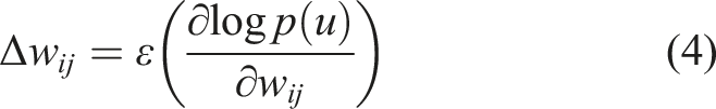
The random weight values are selected to validate experimented variables in the DBN network. With the aim of optimal weight selection, the hybridization of neural networks with SSO has to be performed. Such optimized weights are used to provide minimum validation errors. The SSO Algorithm is framed as a chain using leaders and followers to get the prey.
33
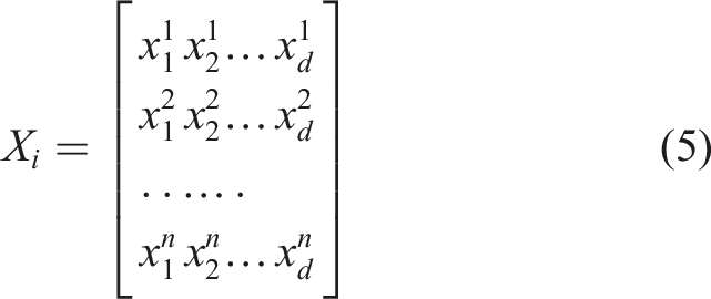
The weight values are separated as both leaders and followers in this work. The leader is responsible for initiation behaviors, and the rest of the followers follow the leader’s movements. Using equation (5), the population
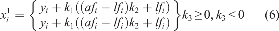
The position for the weight value with the leading role is given in ,
In this optimization algorithm, the major objective is the selection of the best weight values for providing the minimum error through validation.

To update the position of the followers, equation (9) is used,
By considering the optimization time,
Equation (10) is mainly responsible for the optimal weight selection.
Results and Discussions
The comparison of voltage achieved from the same and variable layer lengths of the cantilever beam loaded with tip mass is shown in Figure 7. During beam vibration, a better driving effect from the beam with variable layer lengths is observed. The result proved that the peak to peak voltage is optimal for the cantilever with variable lengths than the same sized beam. The variable-sized cantilever beam has broadened frequency bandwidth, and it helps to enhance the range of peak to peak voltage. Using the uniform lengths of both active layers tends to deform less than the variable length. The maximum bending tendency is optimal for the beam with variable layer size. In this case, the total mass is completely distributed in the inner active layer alone, resulting in more deformation. This also enhances the power output due to the mass and rotary effect. The peak to peak voltage for both the proposed and the conventional bimorph piezoelectric cantilever is 9.2 V and 8.09 V. Comparison of voltage outcome of proposed and conventional approach of a piezoelectric cantilever beam.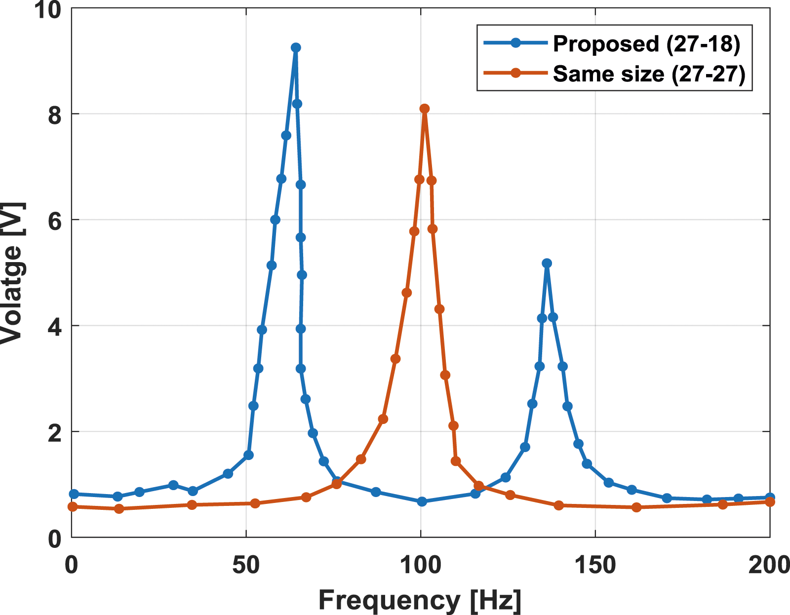
This section examines the influence of layer lengths in the bimorph cantilever beam on power generation. Figure 8 represents the peak to peak voltage analysis obtained from different cantilever beam’s inner and outer active layer lengths. The power generation is superiorly affected by the two-layer lengths. Three lengths were used for the inner active layers (Composite) and the outer active layers (Acryl sheet). The lengths of composite layers are 27 mm, 25 mm, and 23 mm. Analysis of output voltage from the different lengths of the cantilever beam. (a) Inner active length 27 mm. (b) Inner active length 25 mm. (c) Inner active length 23 mm.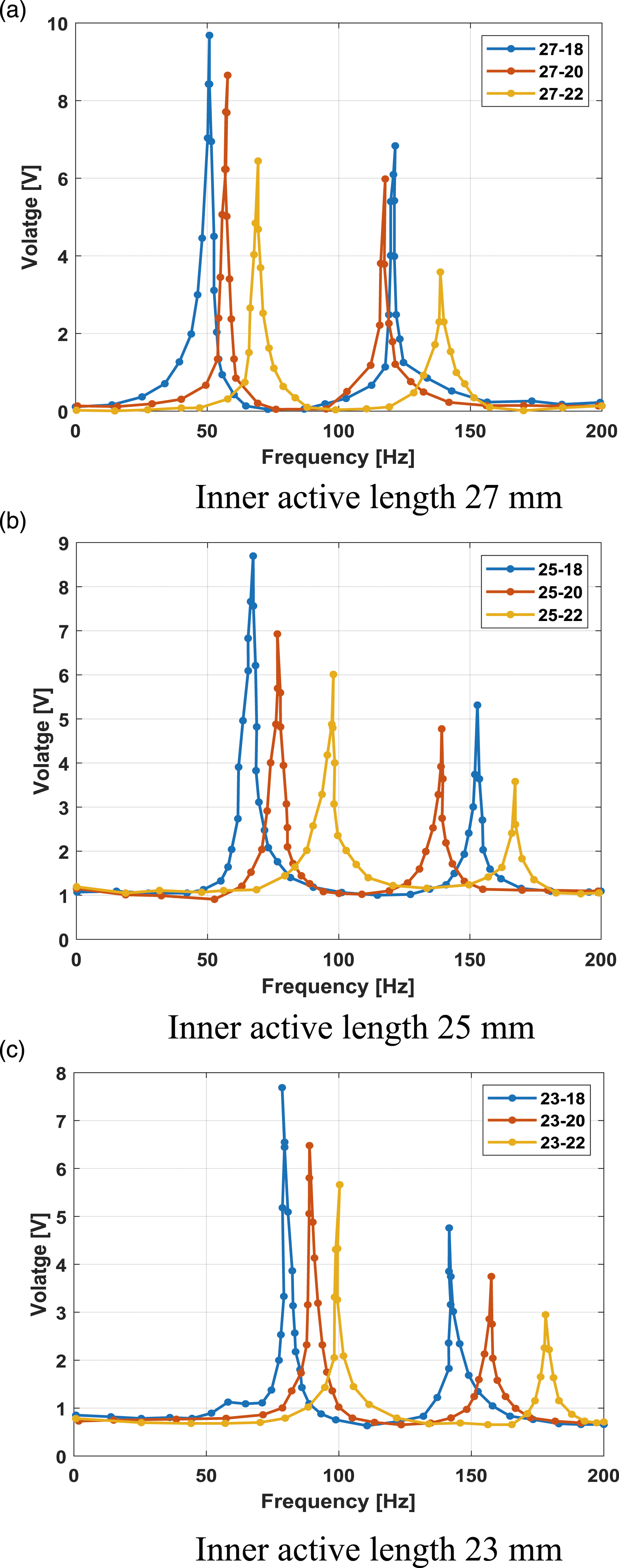
The lengths used for the Acryl sheet are 18 mm, 19 mm, and 20 mm. Compared to the inner active layer, this work considers the minimum length for the acryl sheet due to its lesser weight. In the experiments, the voltage range of the bimorph cantilever is analyzed by varying the excitation frequency up to 200 Hz with the excitation amplitude of 700 mV. As per Figure 7, the maximum amount of voltage is gained from partially distributed layers than the fully distributed layers. In other words, the minimum voltage is observed using the same lengths of both active layers. The figure represents the voltage responses of the cantilever beam with different layer lengths. Figure 8 (a)-(c) proved that the maximum length of piezoelectric composite with minimum outer layer length provides an increased output voltage range.
Voltage Results of a cantilever beam with optimal inner active layer length of 27 mm.
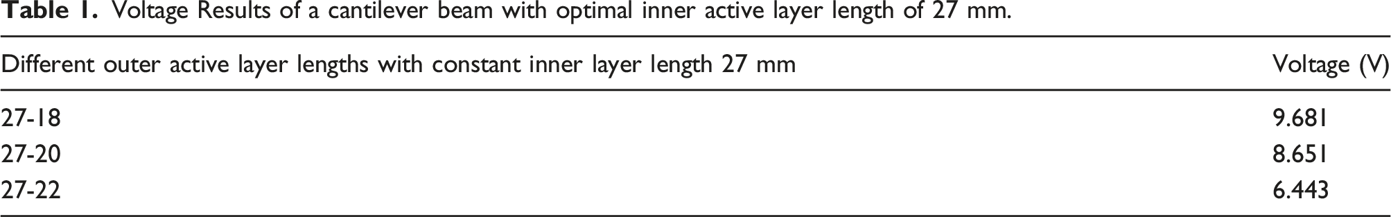
Figure 9 represents the output open-circuit voltage of the optimum piezoelectric cantilever beam (layer length 27-18) for different motor speeds (500 r/min to 1500 r/min) at several resistive load conditions. The gap between each layer is maintained at 7.5 mm during the motor rotation. The result shows that the increased voltage is observed during the maximum motor speed of 1500 r/min. At maximum excitation, the harvester should increase both the vibration and the amplitude level. In addition, the tip mass connecting at the end of the beam contributes to sufficient amplitude generation with minimized resonance conditions. The tip mass works as a damper in this proposed harvester application. The increased voltage range is gained by increasing the motor’s rotating speed and resistive load conditions. At 1500 r/min, the maximum output circuit voltage observed from the proposed composite-based piezoelectric cantilever beam is 21.94 V. By increasing each motor speed level, approximately 2.5 V gets improved. Besides, 1.5 V gets increased during the increase of each resonant condition. Output Circuit Voltage of the optimal cantilever beam (27-18) under different Resistive load conditions for different motor speed.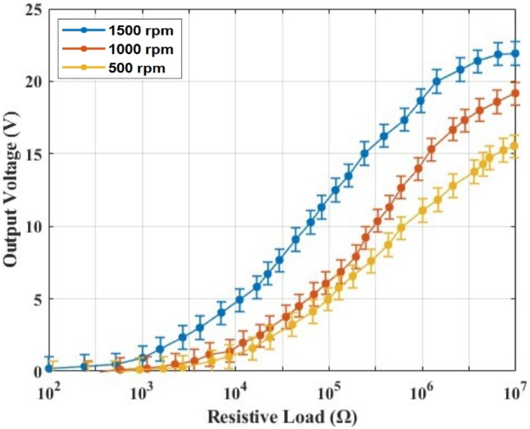
The plot for the overall output power and current of the optimum piezoelectric bimorph cantilever beam is shown in Figure 10 (a) and (b). Like the output voltage, the best power and current characteristics are achieved using the DC motor with a maximum speed of 1500 r/min. However, this trend is the opposite for the resistive load conditions compared with the output voltage. By increasing the resistive loads, the current value tends to be reduced. According to the Gaussian function, the output power is obtained at specific load resistance when multiplying the output circuit voltage and current plot. While the motor rotating speed is 500 r/min and 1000 r/min, the minimum output current is observed to be less than 2.7 mA. Such a similar trend is observed for the output power. The peak power observed at 500 r/min is 9.8 mW, and 1000 r/min is 11.18 mW. However, somewhat dramatic favorable variations are observed the rotating speed of the motor exceeds 1000 r/min. The power obtained from the motor speed of 1500 r/min is 2.5 times higher than that of 1000 r/min. This variation occurs due to the increased rotational frequency. Thus, at 1500 r/min, the peak power and current are 13.67 mW and 2.9 mA. From the figures, both the output voltage and current depend on the resistive load, affecting the peak power. Besides, the magnitude of the current is minimized considerably when the voltage increases. Electrical characteristics of the cantilever beam (27-18) under different Resistive load conditions for different motor speed. (a) Overall Power Analysis. (b) Current Analysis.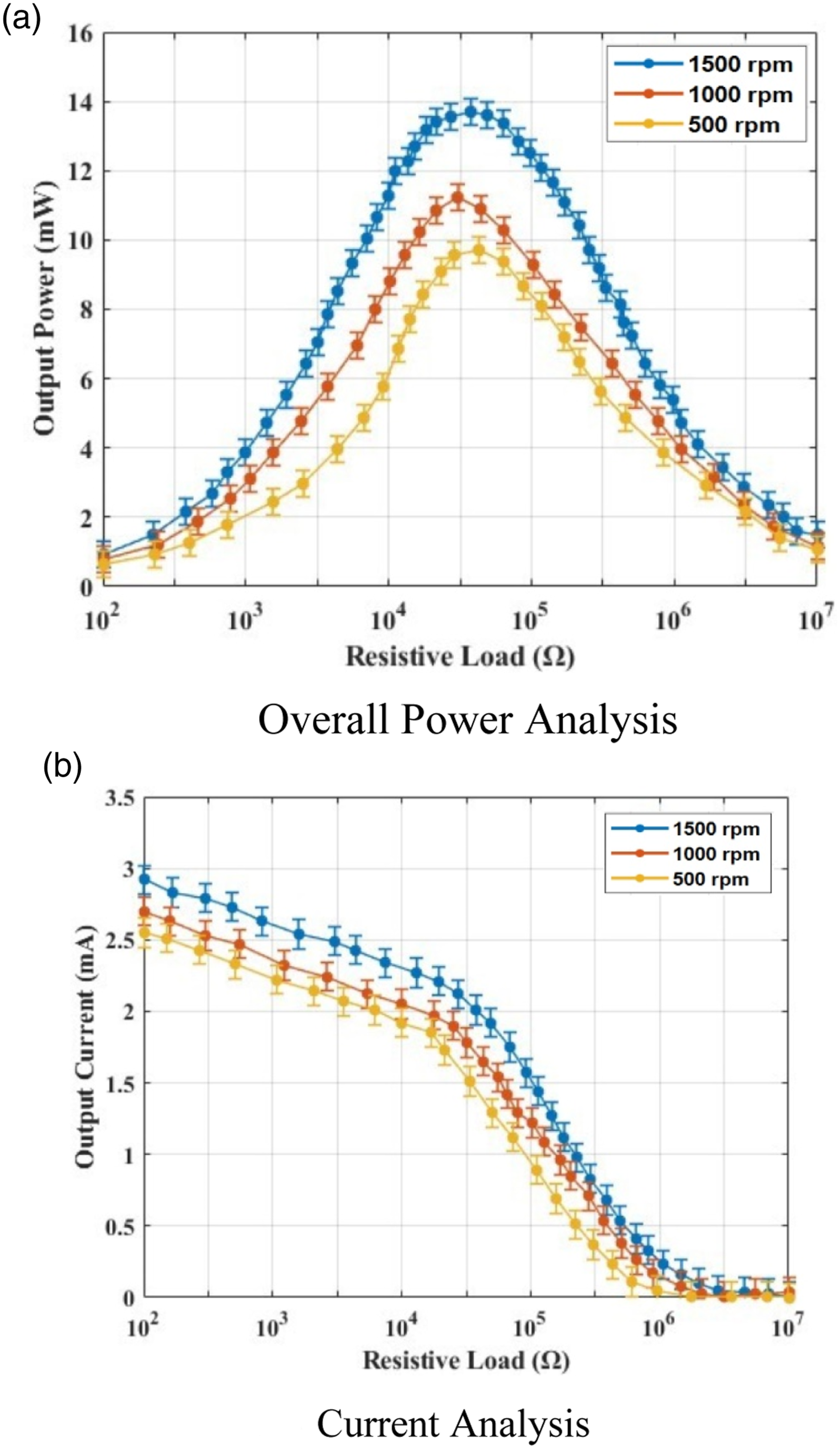
The optimal outcomes obtained from the experimental work are validated using a hybrid Deep Belief Network (weight-optimized DBN-SSO) and are shown in Figure 11. The comparative prediction results for output voltage are represented in Figure 11 (a) and power in Figure 11 (b). From the experimentation, the optimal results are obtained at the motor speed of 1500 r/min. The proposed validation outcomes are also compared with DBN (non-hybrid). The experimental electrical outcomes, such as power and voltage, are better validated in the proposed DBN-SSO model. In hybrid DBN, the Salp Swarm optimization is used to optimize its weights based on the target. As a result, the predicted results are closer to the experimental values and in perfect agreement with each other. At the same time, the weights are randomly updated in the DBN model, so there is a chance for variation in the target values. Comparison of Experimental and validation results obtained from proposed DBN-SSO and DBN. (a) Prediction results of Output Circuit Voltage. (b) Prediction results of overall peak power.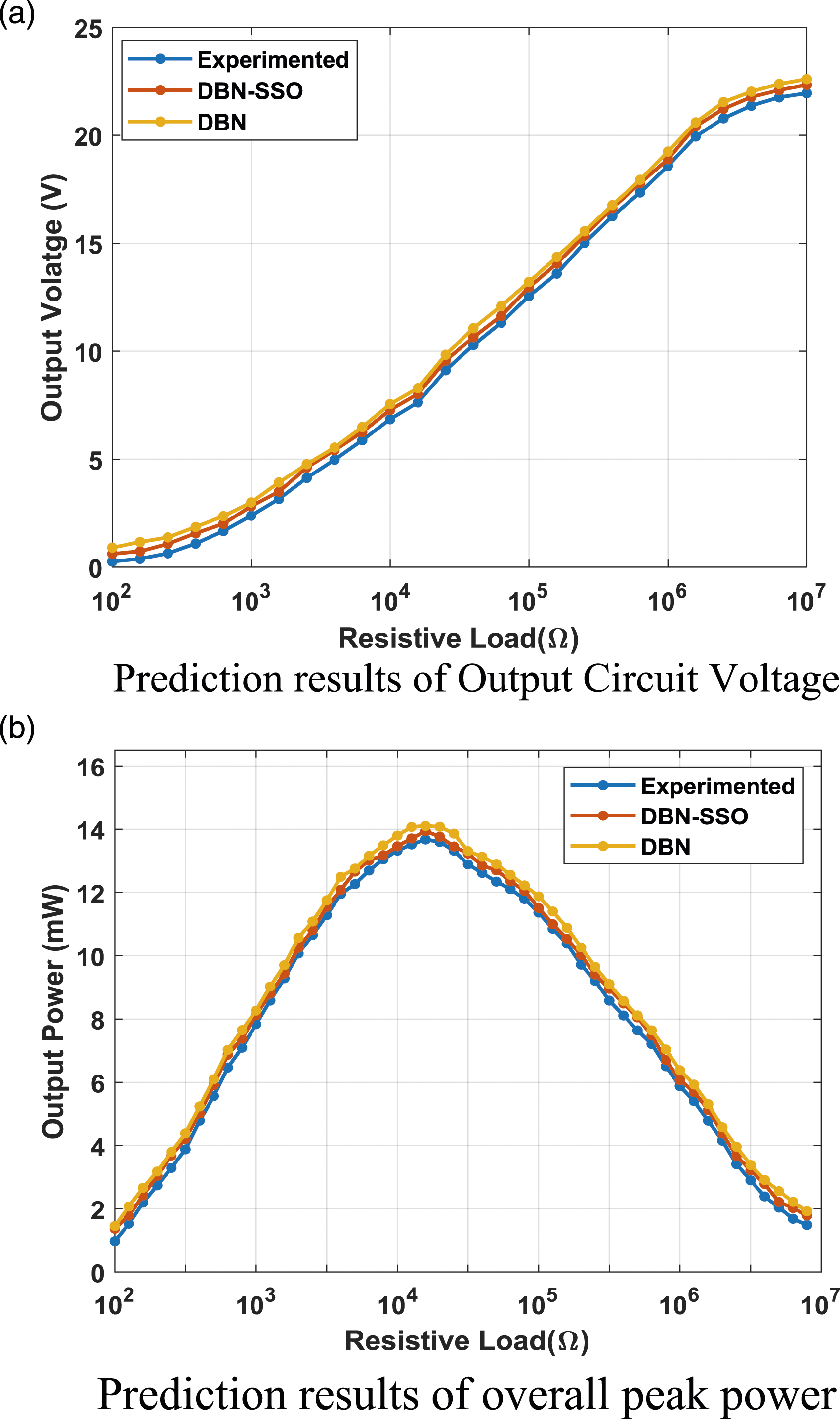
The maximum power and voltage gained during experimentation are 13.67 mW and 21.94 V. The validated range of power achieved from both DBN-SSO and DBN is 13.79 mW and 13.94 mW. Similarly, the validated voltage outcomes are 22.51 V and 22.92 V. The correlation analysis of the proposed DBN-SSO is given in Figure 12. Figure 12 (a) represents the correlation between output circuit voltage and output power, and the correlation graph is given in Figure 12 (b). The validated values are almost closer to or overlap with experimental values, so they are highly correlated (R>0.95). The achieved R-value is greater than 0.99 for voltage and power outcomes in both training and validation cases. Regression analysis. (a) Output voltage. (b) Output power.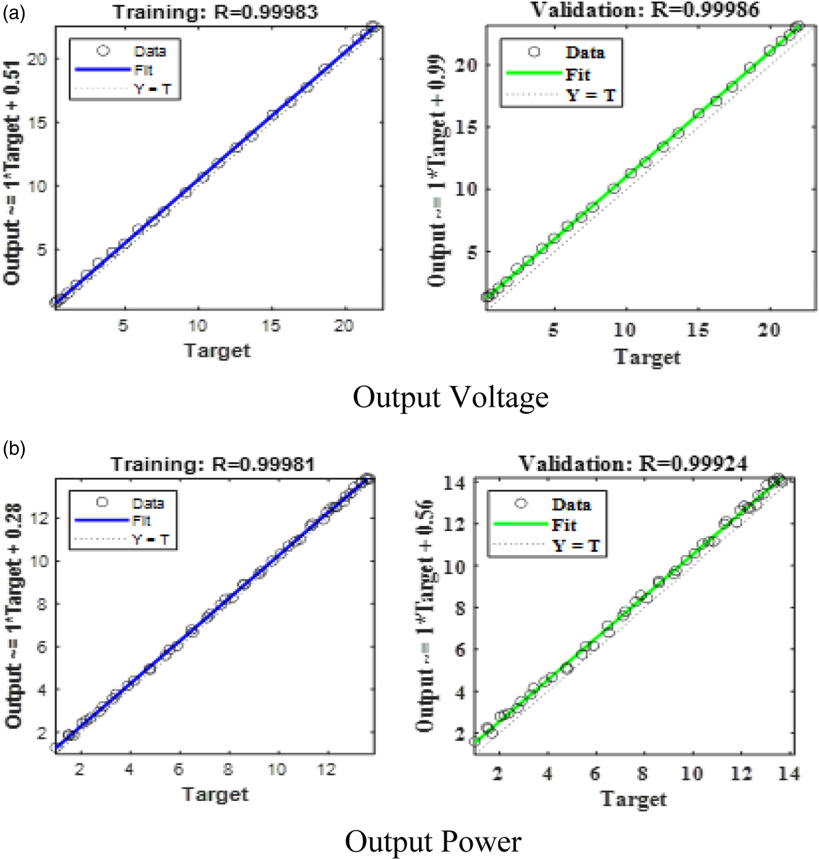
Figure 13 represents the Root Mean Square Error for hybrid (DBN-SSO) and non-hybrid (DBN) prediction models. According to the result, the maximum error is obtained from the DBN due to updating randomized weights. Controversy, in the hybrid DBN model, minimal errors are observed. During the validation of power, the gained RMSE of hybrid DBN and DBN are 0.03 and 0.045. Similarly, the RMSE of 0.23 and 0.32 are obtained from the voltage prediction. Error analysis of both prediction models DBN-SSO and DBN.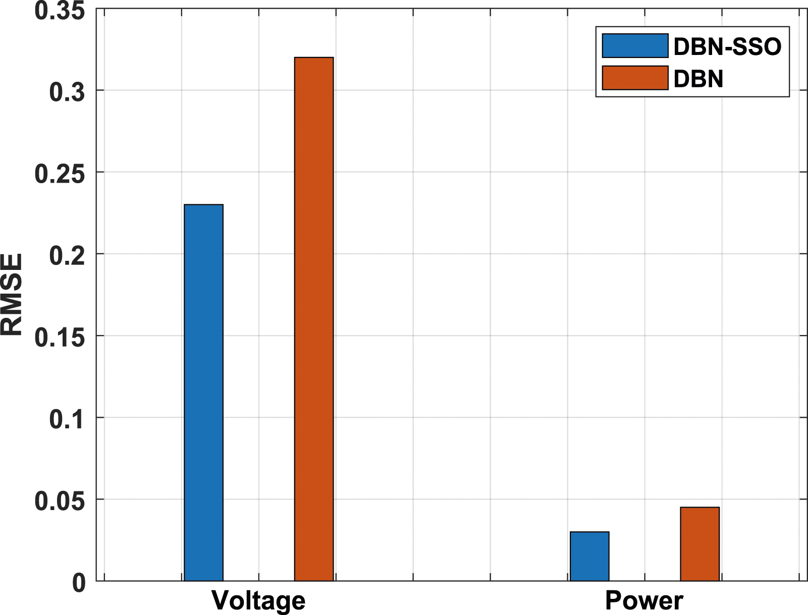
Comparison of proposed study output with several existing methods.
Conclusion
This work analyses the electrical characteristics of the piezoelectric bimorph cantilever beam of different piezoelectric layer lengths. According to the result, the proposed piezoelectric composite performed well and enhanced the output voltage and power of the cantilever energy harvester as expected. In particular, the applied magnetic force is successfully induced adequate vibration in the cantilever beam, thereby strain is accumulated on the proposed piezoelectric material. The optimum motor speed and piezoelectric layer length of the proposed energy harvester are achieved in this study. Finally, the experimental outcomes are validated with the help of Hybrid Deep Belief Network based Salp Swarm Optimization (DBN-SSO). The conclusions derived from this study are discussed as follows, • The increased voltage is observed for the cantilever beam composed of larger inner active layer lengths than similar lengths. The optimum voltage outcomes are obtained using the maximum inner active layer length and the minimum length of the outer active layer (27-18). By varying the frequency from 0 to 200 Hz, an optimal voltage of 9.681 V is observed at 51.06 Hz and 1g acceleration. • The electrical properties of the optimized piezoelectric beam are exceeded at an elevated motor speed of 1500 rpm with different load resistance criteria. • At 1500 rpm, the optimal current, power and voltage results are 2.9 mA, 13.67 W, and 21.94 mV. The peak power achieved at a motor speed of 1500 rpm is 2.5 times higher than at a motor speed of 1000 rpm. • The predicted outcomes gained from the hybrid DBN-SSO and DBN model are 13.79 mW and 13.94 mW of power. Similarly, the validated outcomes for voltage are 22.51 V and 22.92 V. • The proposed DBN-SSO outcomes agree with the experimental values, with a better validation correlation of around 0.99. Also, a very small error rate (i.e.) 0.32 RMSE ensured the reliability of the proposed optimization model. • Besides, the studied geometry of the proposed piezoelectric energy harvesting system is limited due to some difficulties during the fabrication of the cantilever beam (like material wastage, piezoelectric beam damage etc.). Therefore, studies on the proposed piezoelectric length and various beam thicknesses at different mass magnitudes are highly recommended in future works. In addition, advanced machine learning optimization methods can also be implemented to optimize the efficiency of the proposed piezoelectric energy harvesting method.
Footnotes
Declaration of conflicting interests
The author(s) declared no potential conflicts of interest with respect to the research, authorship, and/or publication of this article.
Funding
The author(s) received no financial support for the research, authorship, and/or publication of this article.