
Abstract
Interlocking Particle Structures (IPS) are geometrically stable assemblies, usually fabricated from plate type elements that are interconnected by slotted joints. IPS are demountable and their components have the potential to be used and reused in different structures and configurations. This paper explores the applicability of birch plywood panels, which are characterized by a high surface hardness, for this type of structural system. Experimental tests were conducted to determine the mechanical properties of birch plywood plates. Moreover, IPS connections with different geometrical properties were investigated for two different load exposures: bending and rotation. The characteristics under bending exposure are influenced by the orientation of the face-veneers. For the rotational load exposure, very small strength and stiffness properties have been identified. A linear elastic finite element model is presented that shows a wide agreement with the test results. The study serves as an initial probe into the performance of IPS structures at the component level. Various aspects that are relevant for the design of IPS, such as the assembly, the accuracy and challenges regarding digital fabrication, the durability, and the structural performance are discussed.
Introduction
Over the past decade, advances in digital fabrication and in the development of engineered wood products have substantially increased the design possibilities for geometrically advanced structures made of timber components. One of the first timber structures that featured robotically fabricated elements and joints was the ICD/ITKE Research Pavilion 2010. 1 More recent examples for this are the Wood Chip Barn, designed and built at the Architectural Associations Hooke Park facilities, 2 and the Sequential Roof, developed by Gramazio Kohler Research at ETH Zurich. 3
The focus of the present paper is on Interlocking Particle Structures (IPS), the design and construction of which heavily relies on digital tools and state-of-the-art engineered wood products. Suitable engineered timber products for the basic components are plywood, laminated veneer lumber (LVL), or cross laminated timber (CLT). IPS can be described as geometrically stable assemblies of plate shaped elements that mutually support each other and that are interconnected by linear slotted joints. 4
The basic principle of this assembly technique is not new. It can be found in furniture, sculptures and in other applications. Over the past years, there has been an increased interest in this assembly principle in academia. The New View pavilion, for example, is a spatial structure consisting of mutually supported curved plywood elements that are interlocked via U-shaped cuts. 5 The use of U-shaped incisions in timber panels to form folded and interlocking structures has also been examined in research and research-based teaching at EPFL.6,7
Some IPS configurations, like the one discussed in this paper, are similar to Reciprocal Frame structures, 8 to which some scholars also refer to as Nexorades, 9 or Topologically Interlocking Assemblies. 10 . In the past few years, several computational tools for the design of such structures has emerged.11,12 One of the more recently built examples is the Serpentine Pavilion designed by Alvaro Siza and Eduardo Souto de Moura with Cecil Balmond, in which the interlocking of the structural members is facilitated by mortise and tenon joints.
One of the advantages of IPS is their demountability, which is rooted in the simplicity of the joining principle. The structure can be dismantled and reassembled without causing considerable damage to the components. Using such structures could help to establish a circular economy within the building construction sector. Since the connections in IPS can be easily made and provide clear-cut points for assembly, they are well suited for use in spatial structures. The load-bearing capacity and the load-displacement behavior of the structural system is principally dependent on the material properties of the plates themselves, as well as the connection properties. This paper focuses on investigating the performance of the base modules under certain loading conditions. Similar studies have recently been carried out by Imperadori et al. 13 and Robeller and Weinand. 14 In the case of the latter study, it is observed that the snapping mechanism might make it difficult, if not impossible, to reuse components without having to cut them first.
It is well known that the most efficient way of load transfer in spatial structures is along the axis of the elements it is composed of (Larsen. 15 ) In spatial structures adopting interlocking panels, the main loading scenarios that affect the structural stability are (i) transverse loads that give rise to bending, (ii) loads that give rise to rotation about the main axis of the connection, and (iii) in plane loads causing pull-out. The resistance to pull-out forces of an individual connection is mainly dependent on the friction at the connection interface and accordingly on its fabrication accuracy. Nevertheless, in IPS, pull-out failures are usually prevented by interlocking arrangement of the plates and due to the systematic arrangement of the plates, pull-out loads are usually prevented. In this paper, the focus is on assessing the performance of the base modules under transverse loads that give rise to bending and rotation. The resistance of the connections regarding pull-out forces was not investigated.
Material and methods
The experimental investigation is performed on a prototype, fabricated for an exhibition at Aalto University (Figure 1, left). The structure consists of six interlocking birch plywood plates
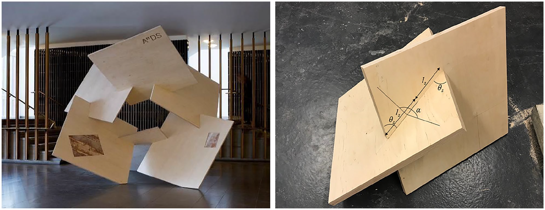
Interlocking birch plywood at the exhibition area at Aalto University (left). Image: Anne Kinnunen. Illustration of a typical test specimen including all relevant geometrical parameters of the connection (right).
Material properties
The base modules were composed of Finnish birch plywood. Birch plywood is an engineered wood product that finds applications in both vertical and lateral load resisting structural elements as well as in miscellaneous applications like decking for transportation vehicles and the hulls of boats. For a comprehensive summary of the mechanical behavior of Finnish birch plywood, refer Veistinen and Pennala. 16 Birch is a good raw material for plywood because of its aesthetic appearance, favorable mechanical properties, and surface hardness. In order to improve its weather resistance, edge sealants are generally used.
The plywood panels used in this study had a nominal thickness of 27 mm. As the panels have been sanded, the measured thickness of the panels was about 26 mm. The panels were conditioned in an environment where the temperature was maintained at
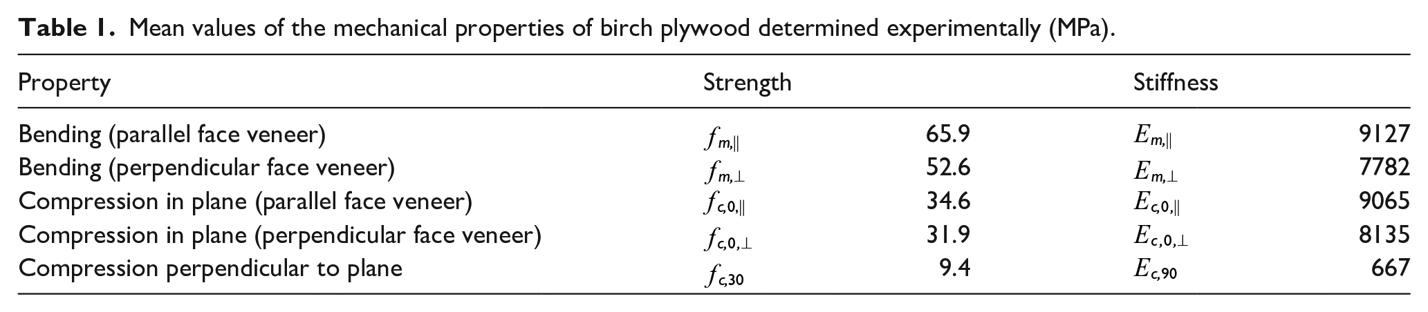
Material tests were performed to determine the strength and stiffness properties in bending and compression. On an average, five specimens were tested to determine each property. The bending tests were carried out in accordance with EN 408 17 and the compression tests were tested according to the provisions in EN 789. 18 For both bending and in-plane compression tests, specimens of two different configurations were used- one in which the load was applied along the direction of the face veneer and the other in which the load was applied perpendicular to the face veneer. The material properties that were determined experimentally are listed in Table 1. In bending, the failure was brittle and characterized by fracture of the veneers on the tension side of the specimen. Under compression loads, both in-plane and perpendicular to the plane, ductile failure was observed. For a more detailed description of the experimental investigations, refer to Aranha et al. 19
Mean values of the mechanical properties of birch plywood determined experimentally (MPa).
Test specimens
For the experimental tests, the pieces were cut from four of the original plywood plates. Each specimen consists of two panels (500 mm ×500 mm) that are interlocked via their slots. The length of the slot was rather similar for all panels
Mechanical properties of panel specimens tested.
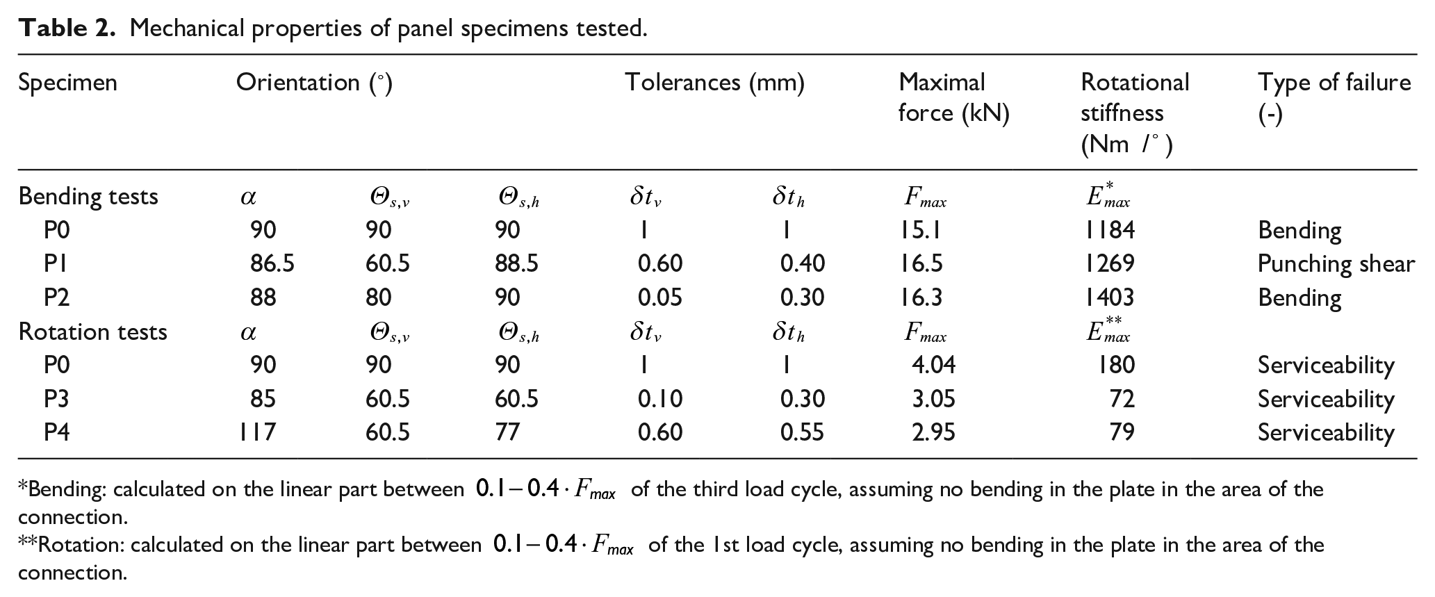
*Bending: calculated on the linear part between
**Rotation: calculated on the linear part between
Test procedure and test set-up
The aim of the tests was to determine the in-service stiffness and load capacity of the base modules. Two types of short-term monotonic tests were conducted on the specimens:
Bending test: Transverse load acting in line with the connection which gives rise to bending.
Rotation test: Transverse load which gives rise to rotation.
The set-up was devised such that the panel on which the load is applied, is orientated horizontally (at the beginning of the test), irrespective of the dihedral angle α. The other panel is held in its position (depending on the geometrical characteristics of the slot) and is fixed at the base. The upward movement of the vertical panel is restrained by a steel frame system such that it does not induce any additional stress in the panel. The load was transferred from a 50 mm diameter cylinder onto the surface of the horizontally held plate through a 50 mm × 50 mm steel section of 10 mm thickness (a plywood plate is used to attach the steel section to the panel). A vertical transducer (designated as 9, in Figure 2, left) was used to measure the displacement below the point of application of the load. Vertical transducers3,4,6,9,17–20 were mounted close to the four corners of the slot in the vertical panel on both the upper and lower surfaces. For the rotational test, four additional transducers1,8,13,15 were mounted close to the slot to measure the horizontal opening of the connection between the panels. For most of the specimens
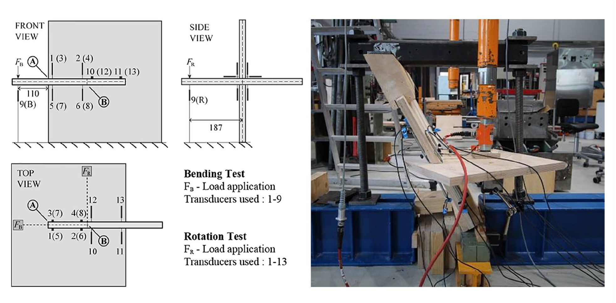
Schematic drawing of experimental setup showing the position of the loading points and the LVDTs, dimensions in mm (left). Illustration of the test setup of specimen P4 (right).
On the reference sample P0, at first, a rotation test (local plastic deformation at slot involving no visible damage to the other parts of the specimen) and subsequently, a destructive bending test was performed. For the rotation tests (specimen P0, P3, P4), a pre-load
Results
Bending tests
When loading the specimens in bending, significant deformations within the loaded (horizontal) plate were observed. Figure 3 illustrates the vertical displacement of the horizontal plate in the interlocking area: The black lines show the deformation near the edge of the slot (Location A, average value of transducer 1, 3, 5, 7), the gray lines show the uplift at the end of the slot (Location B, average value of transducer 2, 4, 6, 8). Specimens P0 and P1 had comparable large tolerances (see Table 2), resulting in large slips (uplift) at a very low load level. With increasing load the rotation of the horizontal plate increases. At the corner (location A), local damage due to compression stresses perpendicular to the grain occurred (see Figure 4).
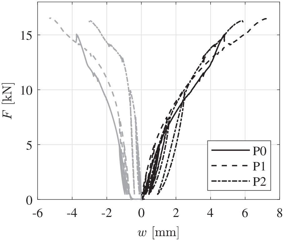
Load displacement curves of the specimens P0, P1, and P2 under bending load. The black lines show the deformation in A (average value of transducer 1, 3, 5, 7), the gray lines show the uplift in B (average value of transducer 2, 4, 6, 8).
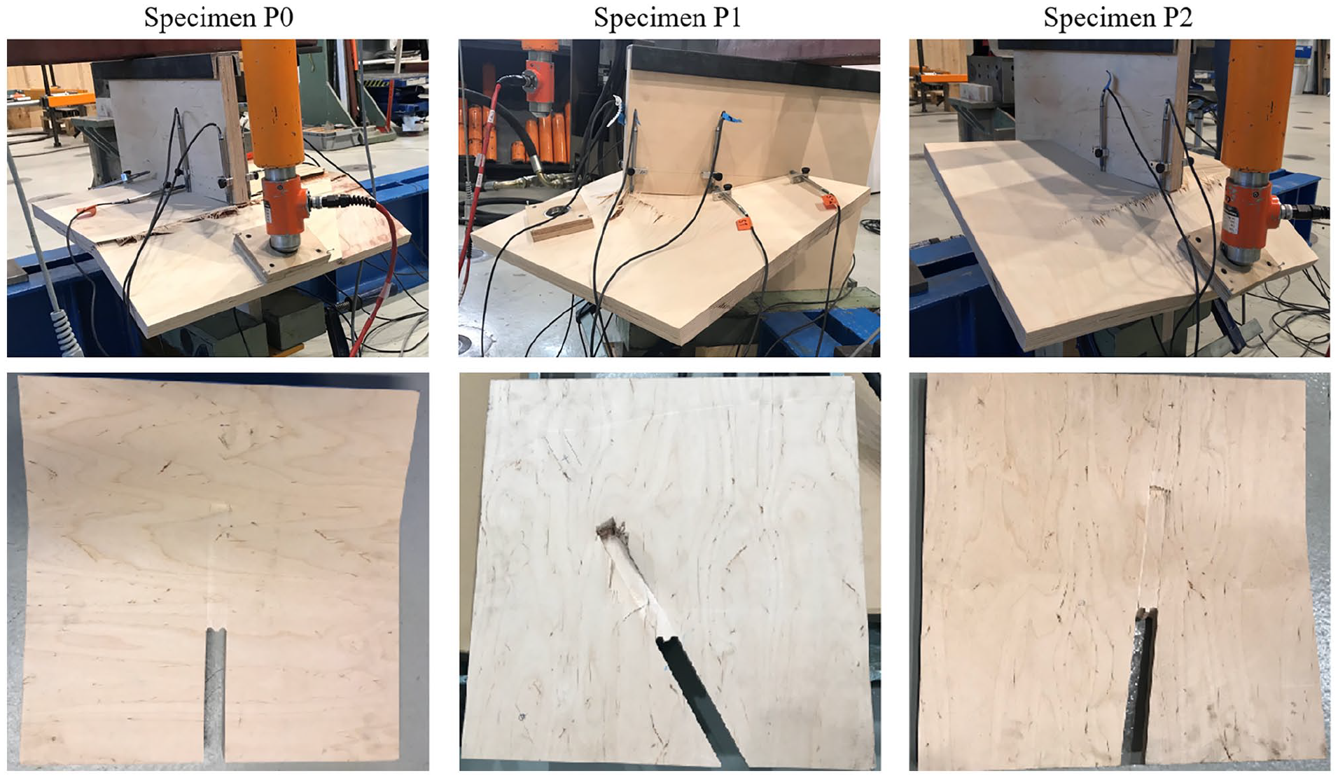
Failure of specimens P0, P1, and P2. Deformation at maximum load (top). Compression areas in the horizontal panel after the test (bottom).
Based on the load-displacement curve, the rotational stiffness of the connection (rotation at the corner) was calculated on the linear part between
The maximum load and failure mode of the specimens are listed in Table 2. In comparison to the rotational stiffness, the variation of the maximum load is rather small, but also related to the orientation of the face veneer. In Figure 4 the failed specimens are illustrated. Two different failure modes can be observed: Bending failure and punching shear failure. Specimens P0 and P2 failed in bending. In these specimens, with increase in load, the lower surface of the horizontal panel bears on the vertical panel and fibers start to undergo crushing because of compression perpendicular to the panel. With a further increase in load, the upper surface of the horizontal panel, which is in tension, starts developing flexural cracks close to the slot. Thereafter, with the increasing load, the cracks propagate through the width of the specimen and failure occurs when the cracks extend through the depth to the core veneers of the horizontal panel. For specimen P0, the flexural cracks extended throughout the entire width of the specimen, while the flexural cracks in specimen P2 only extended up to 80% of the width. This results from the grain direction of the face veneer that was perpendicular to the applied load for P0 and about
In the case of specimen P1 a punching shear failure was observed. During the test a local compression of the lower face of the horizontal panel in the vicinity of the slot was observed. With increasing load, tensile cracks along the grain direction of the face veneer appeared close to the slot. The localized crushing of fibers on the compression face escalated into a punching shear failure.
The specimen size of panels was significantly reduced compared to the original structure. This influences the type of failure and should be considered in the design of an IPS system.
Rotation tests
The panels were found to be highly deformable in the rotation tests (see Figure 5, right). Failure in all cases was due to excessive rotation, meaning the load transmission was not possible anymore. The maximal force for specimen P0 was higher than in specimens P3 and P4. The maximum opening recorded by the horizontal transducers was about 10 mm for all specimens.
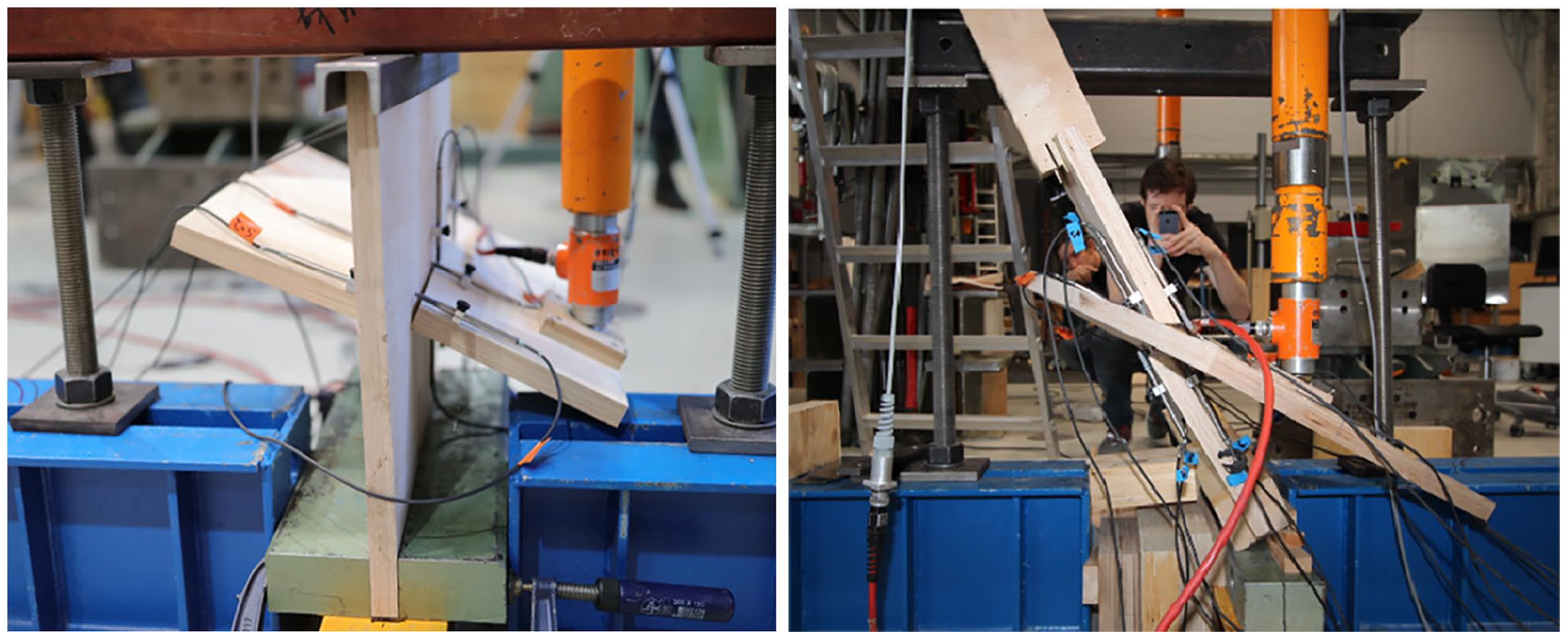
Deformation at maximum load: Specimen P0 (left). Specimen P4 (right).
Figure 6 illustrates the vertical displacement of the horizontal plate at the end of the slots (location B): The black lines show the deformation at the side were the load is applied (average value of transducer 2, 6), and the gray lines show the uplift at the opposite site (average value of transducer 4, 8). The tolerances of specimens P0 and P4, resulted in a slip at a very low load level. Based on the load-displacement curve the rotational stiffness of the connection (rotation at the corner) is calculated on the linear part between
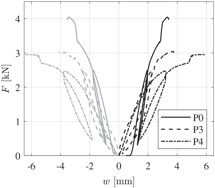
Load displacement curves of the specimens P0, P3, and P4 under rotational load in B. The black lines show the deformation at the side where the load is applied (average value of transducer 2, 6), the gray lines show the uplift at the opposite site (average value of transducer 4, 8).
Finite element model
A 3D solid model was developed using the finite element (FE) software ABAQUS. The mesh consisted in 10-noded quadratic tetrahedral elements (C3D10). The mesh density was specified by restricting the element size to 10 mm. Plywood was defined as an elastic orthotropic material using nine engineering constants. The values for the Youngs moduli and density were taken from the experimental tests. The experimentally obtained values were very similar to the corresponding values given in the Finnish plywood handbook. Since no shear tests were done at the material level characterization, the modulus of rigidity for planar and panel shear were taken from the handbook.
16
The values of Poissons ratio were derived from the values given for birch by Dinwoodie.
20
The material properties are:
Since shear and normal forces are transferred at the connection interfaces of the base modules, surface-to-surface contact was defined. The frictional forces in the tangential direction of the contact surfaces were incorporated by assuming the friction coefficient
Using the FE model the locations of highest in-plane tensile and compression perpendicular to the plane stresses in the specimens could be identified (see e.g. Figure 7). Since the failure of plywood in tension is brittle, it can be assumed that the regions where the stresses exceed the tensile strength of the material correspond to the fracture location. A comparison of the vertical displacement below the loading point with the results from the experimental investigations (Transducer 9) shows a wide agreement for the elastic region. The drawback with the linear elastic model is that it does not simulate the plasticizing behavior in compression. Due to the limited number of specimens tested, it was challenging to define a suitable elasto-plastic behavior representative of the plywood. Since IPS structures are designed with a high degree of redundancy, with an aim to keep the behavior of the structure linear elastic and avoid overstressing and subsequent excessive deformation at the connections, only a simple linear elastic model was developed.
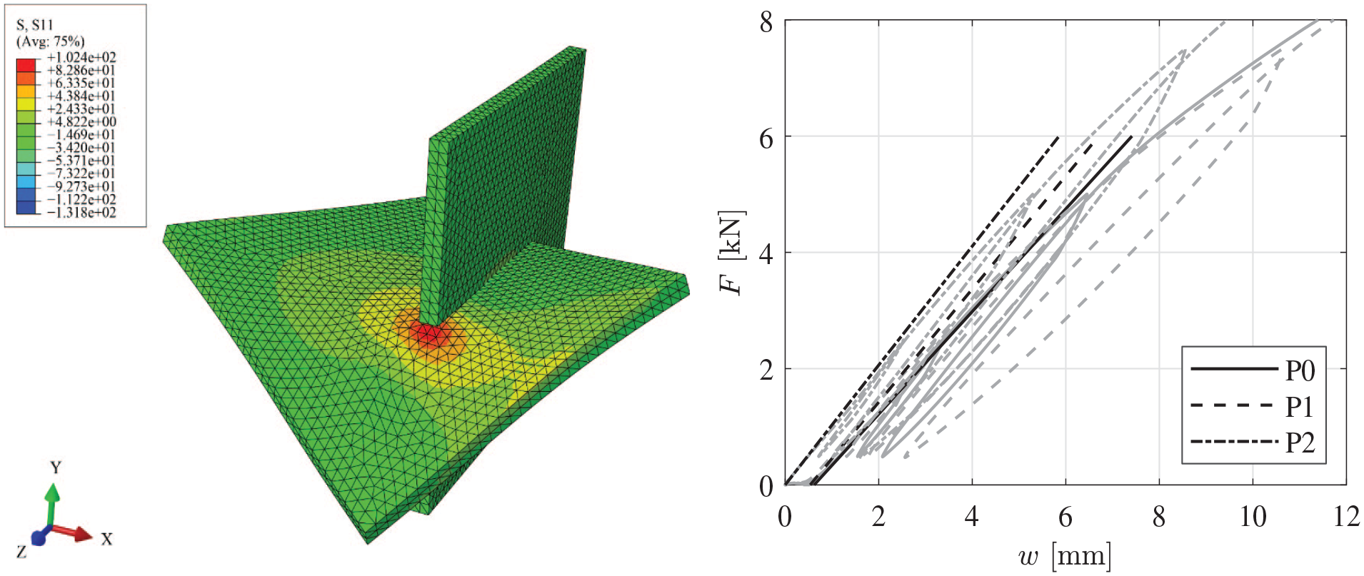
Distribution of the in-plane principle stresses (MPa) along the direction of the face veneer of specimen P1 (left). Comparison between the measured and the simulated deformation below the load application (Transducer 9) (right). The black lines represent the linear elastic numerical curves and the gray lines represent the experimentally obtained curves.
Further aspects
Digital fabrication
As mentioned in Hudert et al., 23 the geometry of the angled incisions and the tolerances involved in their fabrication play an important role for the ease of assembly and the stability of IPS. CNC milling employs cylindrical cutting bits, which results in filleted corners. This is problematic, as the final relative position of two panels, respectively their shared surfaces of contact, cannot be determined in a precise way. Ideally, two panels would be interlocked in such a way that they have one common planar contact surface perpendicular to the axis of insertion. In order to achieve this, the milling of the panels was carried out in two passes. The final geometry of the incisions is visible in Figure 4. In the case of this demonstrator, the fabrication of the cuts was not very challenging. Other configurations with lower angles would require a different and more laborious milling set-up. During the assembly of the demonstrator, the chosen tolerance turned out to be challenging. The cuts were partly too tight for the assembly process. It was rather difficult to fully interlock the panels, due to deformations caused by the self-weight of the panels, as described below.
Assembly
The IPS configuration discussed in this paper consists of three pairs of plywood panels arranged in parallel, see Figure 1. Due to the underlying geometric logic of this configuration, the final assembly step requires the interlocking of two clusters with three panels each. This in turn requires the simultaneous insertion of two panels of one cluster into two of the other one. In the case of the here discussed demonstrator, one cluster was manually lifted and then inserted into the second one from above. The difficulty here were deformations caused by the cluster’s self-weight and the coordination of a simultaneous insertion of the two panels, in order to avoid jamming. The low tolerance of the incisions made this challenging. The assembly location did not make things easier, either. Due to the low ceiling height, it was not possible to use a mechanical crane. The effort related to the assembly is justified by the resulting geometrical interlocking, which, in theory, should also work with higher tolerances. This would also make it easier to disassemble the panels again.
Durability
Wooden structures should always be designed with particular attention regarding weather exposure. For the here-presented IPS this is even more relevant as the load transfer is very local (load concentrations) and takes place in areas of grain-cut timber. The load-bearing capacity of timber depends on the duration and intensity of the applied load. In combination with change of moisture the strength reduction will further increase (see Svensson 24 for a comprehensive overview about the duration of load effect). For outdoor applications, a weather protection is necessary, accordingly.
Summary and conclusions
This paper investigates the structural potential of Interlocking Particle Structures (IPS), which are geometrically stable assemblies, usually fabricated from plate type elements that are interconnected by slotted joints. IPS are ideally configured such that the deadweight of the panels sufficiently counteracts potential pull-out forces. These systems are demountable and their components have the potential to be used and reused in different configurations. The focus of the paper is on the performance of the connections under different loading scenarios. Moreover, it explores the use of birch plywood panels, which are characterized by a high surface hardness, for this type of structural systems.
The paper presents the results of several experimental tests, which were conducted to determine the properties at the material level, and subsequently to identify the elastic stiffness of the connected panels under bending and rotation. The test results are summarized and compared with a linear elastic finite element model. Various aspects that are relevant for the design of ISP structures are discussed, such as the assembly procedure, the role of accuracy, and the constraints of digital fabrication. The latter affects the joint tolerances, which need to be aligned with the assembly requirements in order to avoid overstress during or after assembly. Other relevant aspects are the durability, as well as the structural robustness. The key insight from this study is the low load-bearing capacity of the connection when rotationally loaded around its longitudinal axis. The tests also indicated that the rotational stiffness of the connection is very low. It is therefore necessary to arrange the plates and slots in order to prevent rotational load exposures around their longitudinal axis. This is an important input for the design of geometrically different IPS configurations in the future.
The featured studies serve as an initial probe into the performance of IPS at the component level. Since the tests were performed on a very limited number of specimens, a correlation of the rotational stiffness with the joint tolerances is not provided. The specimens were cut from an exhibition structure and accordingly there was no choice in the selection of the angles. It must be also noted that the tests were carried out on conditioned specimens with stable temperature and humidity levels. Large changes of the moisture content will obviously affect the stiffness and strength properties of the panels themselves and should therefore be avoided. For moderate changes in environmental exposure, the plywood plates are assumed to be form-stable, with minimal impact on the overall behavior.
The authors would like to thank everybody that contributed to the fabrication and erection of the demonstrator as well as the testing of its joints, and in particular the head and team of Aalto Universitys Chair of Design of Structures.
Footnotes
Declaration of conflicting interests
The author(s) declared no potential conflicts of interest with respect to the research, authorship, and/or publication of this article.
Funding
The author(s) received no financial support for the research, authorship, and/or publication of this article.