
Abstract
In vitro test methods are challenged by the multi-factorial nature of head-neck taper connection tribocorrosion due to the consequences of simplification. Incorrect study design and misinterpretation of results has led to contradictory findings regarding important factors affecting head-neck taper tribocorrosion. This review seeks to highlight important considerations when developing in vitro test methods, to help researchers strengthen their study design and analyze the implications of others’ design decisions. The advantages, disadvantages, limitations and procedural considerations for finite element analyses, electrochemical studies and in vitro simulations related to head-neck taper connection tribocorrosion are discussed. Finite element analysis offers an efficient method for studying large ranges of mechanical parameters. However, they are limited by neglecting electrochemical, biological and fluid flow factors. Electrochemical studies may be preferred if these factors are considered important. Care must be taken in interpreting data from electrochemical studies, particularly when different materials are compared. Differences in material valence and toxicity affect clinical translation of electrochemical studies’ results. At their most complex, electrochemical studies attempt to simulate all aspects of headneck taper connection tribocorrosion in a bench top study. Effective execution requires in-depth knowledge of the tribocorrosion phenomenon, the involved mechanisms, and their measures such that each study design decision is fully informed.
Introduction
Modularity in hip replacement prostheses has become increasingly popular to reduce the necessary stock and aid accurate reconstruction of the patient’s anatomy. 1 The femoral head and stem connect via matching tapers. Common metals used for these components (cobalt-chrome and titanium alloys) rely on a passive oxide film to resist corrosion. However, excessive loading causes micromotion and fracture of the oxide films, exposing the underlying bulk material to corrosive attack. Over time, repetitive loading and repassivation develops a corrosive crevice environment within the taper connection, leading to significant component wear, debris release, and revision surgery in severe cases.
Tribocorrosion is the synergistic combination of tribological and corrosive material degradation. Depending on mechanical, electrochemical, material, and environmental factors, tribocorrosion synergism may be protective, as is the case with self-healing or self-lubricating surfaces, or may be harmful and accelerate material degradation. 2
Tribocorrosion may be harmful where corrosion follows removal of a metal’s passive oxide layer by sliding, fretting, microabrasion and/or erosion wear. Sliding wear occurs when two bodies move relative to one another under pressure. Third body wear may occur if there is abrasive debris between the two bodies. Fretting is similar to sliding wear, except it occurs under small amplitude reciprocal motion. Fretting is a combination of abrasive and adhesive wear following the slip-stick mechanic occurring with each reciprocation. Microabrasion is the result of wear due to microscopic abrasive material, such as with a slurry formed from wear debris. Erosion may occur following relative motion or impingement between a surface and cavitation bubbles, liquid flow, or solid particles. Each of these tribological wear mechanisms could result in depassivation and corrosion where in their absence the metal would otherwise be relatively inert. Tribocorrosion may be extended to include biological factors such as bodily fluids or presence of particular cell types (termed bio-tribocorrosion). As such, tribocorrosion research requires expertise from mechanical, chemical, electrical, biological, medical and material science fields. The importance of the interaction between these fields is gaining recognition, with biomedical research interest in tribocorrosion growing far faster than the individual tribology or corrosion domains. 3 Tribocorrosion at the head-neck taper connection involves material degradation by mechanical and corrosive means via complex interplay of tribological, electrochemical, fluid mechanical and biological factors (Figure 1). Mechanically, relative motion at the head-neck taper connection results in wear of the femoral head and stem at the mated surfaces. The head-neck taper connection’s corrosive wear process has been termed mechanically assisted crevice corrosion (MACC). The process is described by Gilbert and Jacobs, 4 and involves mechanical, electrochemical and fluid flow factors. More recently, biological factors have also been identified 5 and termed cell-accelerated corrosion (CAC). 6 In vitro studies are challenged by head-neck taper connection tribocorrosion’s multifactorial nature and inherently involve simplifications. At their most complex, invitro simulations attempt to replicate the taper connection’s failure process. However, no test method to date has perfectly done so. 7 A systematic review of factors affecting head-neck taper connection fretting-corrosion included 91 studies but found inconsistent or inconclusive results for over 70% (25/35) of the factors investigated. 8 Inconsistent and inconclusive evidence may be the result of different study designs without appropriate consideration of study design decisions. An improvement in invitro study quality may improve clinical translation.
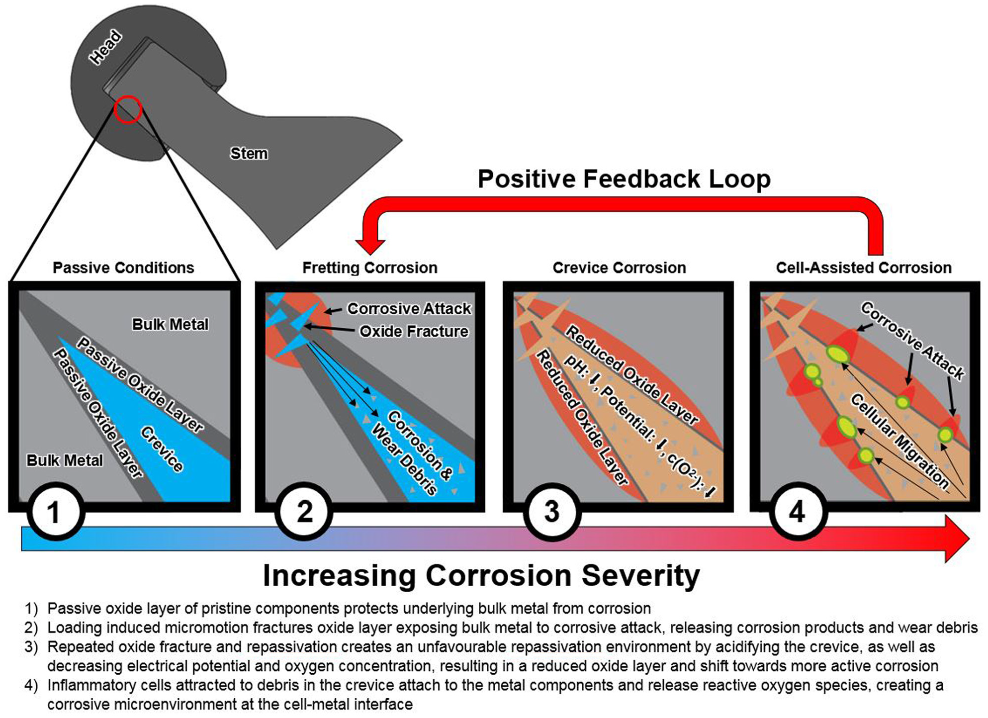
Key components of the taper connection tribocorrosion process, highlighting importance of material properties (stage 1), tribological wear (stage 2), electrochemical and fluid flow factors (stage 3) and biological factors (stage 4). Note the process outlined here is non-exhaustive and may differ particularly with different femoral head materials (metal, ceramic, ceramicized metal).
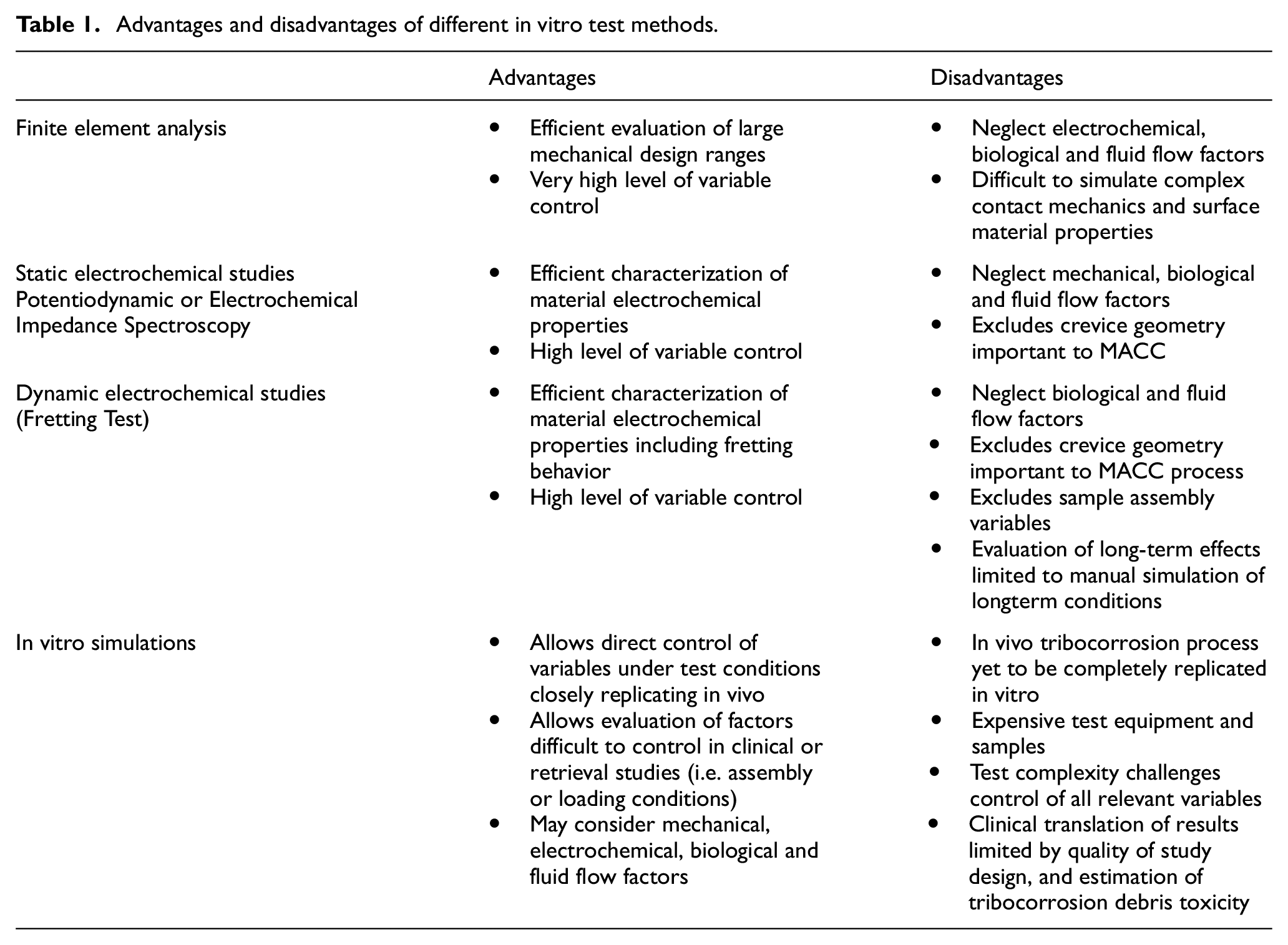
This review seeks to highlight important considerations when developing in vitro test methods, to help researchers strengthen their study design and analyze the implications of others’ design decisions. The advantages, disadvantages, limitations and procedural considerations for finite element analyses, electrochemical studies and in vitro simulations related to head-neck taper connection tribocorrosion are discussed (Table 1).
Advantages and disadvantages of different in vitro test methods.
Finite element analysis
A typical finite element (FE) analysis involves an assembly of femoral stem and head component computer models subject to some external load and monitoring a resultant mechanical parameter at the taper connection’s contact elements. Due to the multifactorial nature of head-neck taper connection tribocorrosion, FE analysis is particularly useful for controlled and efficient investigation of vast parameter sets. Unlike studies involving physical components, the sample size may be scaled with little additional resources, aside from additional analysis time. However, analysis time is not a trivial consideration. A single simulation may require up to 72 h to complete, 9 depending on complexity and processing power, and parametric investigations may require hundreds of simulations. 10 But a well-designed FE study allows investigation of a multitude of contributing factors in a well-controlled manner. Therefore, FE analysis is well suited to broad investigational research to direct future efforts. An example of such a study was executed by Donaldson et al., 10 where 400 parameter sets were simulated across a range of prosthetic designs. Executing a similar study is prohibitively expensive in a bench top test or challenged by confounding factors in a clinical study.
FE analysis’ usefulness is limited by the assumptions and simplifications necessary to allow computation. To date, FE analyses have not modeled the complex chemical processes that are part of tribocorrosion. Therefore, FE models focus on mechanical wear between the mated head and stem. As a result, wear resulting from galvanic or crevice corrosion that occurs in the absence of loading is not considered. Furthermore, excluding corrosion processes may lead to false conclusions. For example, longer taper length may reduce tribocorrosion by effectively increasing distal taper diameter or ensuring the trunnion’s taper is terminated outside of the head’s bore to avoid stress concentration.11,12 Conversely, increasing taper length may increase corrosion by creating an unfavorable crevice geometry, 10 and increase the area of material undergoing corrosion, such that fretting-corrosion is increased. 13 FE analysis tends to detect only the mechanical effect, and concludes that increasing taper length reduces tribocorrosion, as was the case in an FE study by Kluess et al. 14 However, retrieval analyses have not been so conclusive, some finding shorter 11 or longer 13 tapers unfavorable. Therefore, the results of an FE study must be carefully considered alongside potentially competing contribution of non-mechanical effects.
The FE method is further challenged by the head-neck taper connection’s complex contact mechanics. Simplifications related to the CAD models, discretization, material properties, contact, loading, and output may introduce error and must be considered when interpreting results. Ideally, the least complex model is used which accurately reproduces all relevant parameters. This is difficult to achieve considering the headneck taper connection tribocorrosion phenomena’s multifactorial nature.
CAD models are typically truncated to reduce the model volume and subsequently the computational requirements. CAD models may be as simple as a tapered rod and sleeve,10,15 or as complex as the entirety of the prosthesis and surrounding anatomy. 9
Models may be simplified by sectioning along the axis of symmetry, effectively halving the computational requirements. Intermediate complexity models include the complete femoral prosthesis, 16 or the entirety of the femoral head and stem’s neck. 17 The exclusion of particular geometries must be carefully considered. Dyrkacz et al. 17 proposed in their FE study that increasing head diameter increases the head’s stiffness, and thus affected the taper connection mechanics. Femoral neck’s flexural rigidity has been identified as potentially affecting taper connection tribocorrosion in a multicenter retrieval study, 18 thus its exclusion may be to the detriment of the FE analysis. Conversely, more complex studies require greater computational resources, thus their scope may be limited for practical reasons. Additionally, more complex models require more assumptions (such as at the contact between the stem and bone or at the head and cup), with each potentially affecting the simulation’s validity. Discretization is the process whereby the complex model is meshed into simplified elements. Although the geometry of the connection is simple, the stress distribution through components may be complex, thus requiring a highly refined mesh. In published studies, the mesh size for taper connection FE analyses has ranged from tenths of a millimeter 9 to 1.5 mm. 14 More sophisticated second-order elements may be preferred at the contact surface with first-order elements elsewhere in the model. 10 Model convergence must be validated by a mesh refinement study. Published studies have employed a mesh convergence criteria ranging from 3% to 10%.10,17 The mesh convergence criteria are a factor in indicating the model’s accuracy but must be considered alongside all other assumptions to evaluate a model.
Bulk material properties are readily available for many implant materials. 19 However, in head-neck fretting-corrosion studies the important failure mechanism may be fracture of the passive oxide layer. The oxide layer’s mechanical properties may be vastly different than the bulk material. For example, cobalt-chrome alloy is harder than titanium alloy; however, titanium alloy oxidizes preferentially, and oxidized titanium alloy is harder than unoxidized cobalt-chrome. 20 This has been proposed as a potential mechanism for the imprinting pattern of rough titanium alloy stem tapers within the cobalt-chrome head’s bore.11,21–23 Furthermore, the mechanics of passive oxide layer removal is an important consideration when evaluating the output of the model. The oxide layer may break off to produce particulate debris; however, only fracture of the oxide layer is required, which occurs at much lower stresses. 24 Sufficient strain for fracture is developed in titanium alloy’s oxide layer during elastic deformation of the bulk metal, whereas stresses closer to the bulk metal’s hardness is required to fracture cobalt-chrome alloy’s passive oxide layer. 25 Therefore, stresses and strains to initiate fretting-corrosion may vary with different mechanisms for different materials, and once initiated the material properties may be dynamic.
The contact surface setup is central to the FE model. As output parameters are typically taken from nodes at the contacting taper surfaces, assumptions here directly affect results. Total taper contact may underestimate the resultant surface stress 16 because angular mismatch has been identified as an important factor.10,15,26 Stem trunnions with machined ridges can create asperity contact which serve to further complicate the FE model. Coefficient of friction (COF) is a central parameter to characterizing the contact mechanics. 10 Previous FE studies have used COFs ranging from 0.05 to 0.55.9,14,15,17,27 Swaminathan and Gilbert 28 investigated the coefficient of friction with Ti6Al4V-Ti6Al4V, CoCr-Ti6Al4V, and CoCr-CoCr material couples in a pin-on-disc study. They found an initial transient increase in COF (to about 0.8) for all material combinations at lower stress (approximately<70 MPa) which dropped to 0.6 for Ti6Al4V-Ti6Al4V and 0.3 for CoCr-Ti6Al4V and CoCr-CoCr at higher stress. A higher, non-linear COF may be more appropriate than that previously employed, and COF varies significantly with material combination. Fessler and Fricker 29 investigated the COF for a range of combinations between ceramic, CoCr and stainless steel heads on CoCr, Ti6Al4V and stainless steel trunnions. This study yielded COF ranging from 0.13 to 0.2 for the various material combinations, with the presence of lubrication having little effect. Both these experimental studies investigated pristine components. Retrieval analyses have shown significant wear11,30,31 and presence of adherent debris 32 which may affect the COF following a period of implantation.
FE models are typically subject to two stages of loading, first to simulate assembly then in vivo usage. Components may be assembled by a prescribed displacement, 15 static load,14,17,27 or impact load.9,10 Increasing assembly load has been shown to increase taper disassembly strength,33,34 resistance to micromotion, 35 and resistance to corrosion initiation. 36 Assembly load applied by orthopedic surgeons has been shown to range from 273 to 7848 N. 37 Lavernia et al., 38 Nassutt et al. 37 and Heiney et al. 39 each independently investigated the assembly load applied by orthopedic surgeons, and reported average loads of 1633, 2927, and 4409 N, respectively. A 2000 N axial assembly load is called for in the standard ASTM F1875 for fretting-corrosion testing of the head-neck taper connection, 40 and is considered to represent assembly by a hammer. 41 Following assembly, the model is subject to a prescribed loading to simulate in vivo usage. Head-neck taper connection tribocorrosion is a long term wear phenomena, so FE models are typically subject to simulated gait loading due to its repetitive nature in vivo.9,10,14,16,27 Published studies vary widely in the complexity of their simulated gait. The most complex analyses follow a complete gait cycle, as per ISO standard 14242-1 42 or as measured by telemeterized prostheses.43–45 Simplified analyses only simulate the peak loading experienced during gait,14,16,17,27 excluding torsional loading resultant from friction at the articulation. Pereira et al. 46 found head diameter as an important co-factor with head abrasive wear in predicting taper damage in a retrieval study of metal-on-polyethylene THA components. Femoral head abrasive wear increases articular friction and frictional torque experienced at the taper connection. Panagiotidou et al. 47 found in a bench test that increasing frictional torque significantly increased taper fretting-corrosion. Bishop et al. 48 found in a hip simulator study with serum lubricant that the maximum frictional moment experienced during gait varied from 2.0 to 7.9 Nm for commercially available MoM, MoP, and CoP articular combinations. Jauch et al. 36 demonstrated that taper connection corrosion was initiated at torque levels as low as 4 Nm; therefore, inclusion of torsional loading is important. Another important consideration for the applied load is its orientation. Retrieval analyses have identified distinct wear patterns as rotational around the taper connection’s axis, pistoning along the taper connection axis, and toggling of the head on the stem’s trunnion in the coronal plane.49,50 Rotational wear is the result of rotational loading, as described above. Pistoning versus toggling wear depends on the orientation of the load and component geometries. Pistoning is more likely with more axially oriented loading, whereas toggling is more likely when the moment arm from the taper engagement level and the axis of loading is increased, as with high lateral offset femoral heads.10,41
Finally, the output parameter of interest must be selected. Commonly reported outputs are micromotion, surface stress, contact pressure, and calculated wear.9,10,14–17,27 Micromotion should be calculated as the sliding distance at each contact element, such that the distribution of displacements may be analyzed to characterize the rotational, pistoning and toggling wear mechanisms.49,50 Surface stress may be adequate for quantifying surface abrasion, but as described in relation to material properties, surface stress alone may not be adequate to predict passive oxide layer fracture that commences corrosion. Calculation of fretting work may be preferred, which serves to estimate the fretting wear contribution to head-neck taper connection fretting-corrosion. Fretting work is calculated by multiplying the contact pressure by the element area and sliding distance. 10 In accordance with the Archard relationship, 51 linear wear depth is directly proportionate to the fretting work, and may be calculated by multiplying the fretting work by the wear factor. The wear factor has not been determined for any particular head-neck taper connection combinations, but may be informed by previous studies of metal-on-metal hip articulations. 52 Elkins et al. 9 have previously employed a wear factor of 1.13 × 10⁻⁸ mm 3 /Nm. This value was determined by trial-and-error, matching an FE model of a metal-on-metal hip resurfacing prosthesis wear with measured values from a hip simulator. Therefore, it is based on a highly polished CoCr-CoCr articulating pair, with fluid film lubrication and little entrapped wear debris. This is not the case, as taper connections are relatively rough, 53 often include metals other than CoCr, 54 do not have fluid film lubrication, and entrap considerable debris. 32
Considering the degree of simplification at each step of the FE method, validation of the final results is very important. Validation is carried out by performing a physical test similar to the FE model, to directly quantify the model’s predictive accuracy. Micromotion is a useful parameter for validation due to its ease of measurement and calculation. 10 Micromotion may be measured via windows machined into the femoral head 55 ; however, eddy current sensor 56 or laser 57 methods may be preferred for an intact taper. Micromotion displacements may be isolated after removing elastic deformations estimated by monoblock studies or other FE simulations. 56 Exclusion of physical validation for head-neck taper connection FE models is not uncommon, whether it is due to their preliminary nature or resources required, it is to the study’s detriment.
Electrochemical studies
Electrochemical studies generally refer to in vitro bench top studies that monitor sample electrical activity in a simulated corrosion scenario. These studies can be specifically designed to investigate any factor affecting corrosion. Considering the range of mechanical, electrochemical and biological factors affecting head-neck taper connection tribocorrosion, there is an equally wide range of specialized test protocols that may be employed. At their most complex, electrochemical studies become in vitro simulations, where efforts are focused on replicating clinical findings.
At their most simplified, electrochemical studies may measure a material’s open circuit potential (OCP), polarization curve, or electrochemical impedance. Open circuit potential (OCP) is the potential of the sample in the absence of electrical connections.
The OCP is an indicator of the metal’s nobility, with higher OCP being less likely to corrode. The OCP can be measured simply by placing the sample electrode in solution with a reference electrode and measuring the potential difference using a potentiostat. A polarization curve is constructed following a potentiodynamic test by placing the sample in an electrolyte, varying the applied potential and measuring the resultant current density such as per ASTM G61. Analyzing the polarization curve can provide insight into the corrosion behavior, such as the transition from passive to active corrosion region, or the minimum potential where pitting occurs. Following Tafel’s method, a Tafel plot may be used to determine useful properties of the electrochemical reaction, such as the corrosion potential and current. Corrosion potential, like OCP, indicates the metal’s nobility, with higher values indicating less susceptibility to corrosion. Corrosion current indicates the corrosion rate, with higher values indicating a greater corrosion rate. Alternatively, the corrosion behavior may be investigated by Electrochemical Impedance Spectroscopy (EIS). In this type of study, an alternating current is applied to the sample at the corrosion potential, and the sample’s response is used to fit an equivalent circuit. The resistance for the equivalent circuit is a measure of the metal’s corrosion resistance. EIS studies often characterize an individual metallic sample; however, similar techniques may be applied to fretting couples. 58 In a fretting corrosion EIS experiment, factors affecting fretting corrosion behavior beyond the sample’s material properties may be investigated, including the passive layer behavior in the presence of proteinaceous fluid. 58
When mating dissimilar metals, galvanic corrosion must be considered. To determine the galvanic potential between mated materials, the corrosion potential may be estimated using each material’s polarization curves, or by directly coupling the materials in electrolyte and monitoring the electrical activity. 59 Previously, galvanic corrosion was thought to be the reason for increased corrosion observed in head-neck combinations with dissimilar metal alloys 60 and may continue to be an important factor; however, the currently prevailing hypothesis is that of mechanically assisted crevice corrosion (MACC) 4 and more recently cell-accelerated corrosion (CAC). 6
Many metals used in hip implants rely on a passive oxide layer for corrosion resistance. The oxide layer’s integrity and the material’s repassivation behavior may be studied by holding the sample in an electrolyte and scratching the surface with a hard stylus. Fracture of the oxide layer is noted when transient repassivation related electrical activity is measured. The oxide layer’s integrity is measured by the fracture load. Goldberg and Gilbert 25 performed one such study to compare the surface of CoCr and Ti6Al4V alloy to a novel TiN/AlN coating. Monitoring the transient repassivation behavior, Goldberg and Gilbert additionally investigated the mean current (oxide layer intact), peak current (directly following oxide fracture), as well as time constant (measure of repassivation speed) versus potential, to estimate the number of metal ions released during repassivation. However, it is difficult to accurately calculate the number of metal ions released due to the alloy’s varied chemical composition. 25 Furthermore, Goldberg and Gilbert used SEM imagery to analyze the surface hardness and characterize their novel coating’s adhesion qualities. Hertzian contact stresses may be calculated to better understand the mechanical behavior of the oxide layer, and to estimate its hardness. 61 Fretting tests allow tribological and electrochemical analysis of a fretting couple. In this type of study, fretting is simulated by articular micromotion of the mated components under an applied load. Similar electrochemical properties may be measured throughout the fretting cycle as are measured in other electrochemical studies, and additionally tribological parameters related to contact friction can be measured. Monitoring the component displacement and tangential frictional force, the friction coefficient and energy dissipated during a fretting cycle may be calculated. Energy dissipated is the work done by the frictional force (frictional force x displacement), and has been found proportional to the wear volume. 62 Friction energy dissipated during a fretting cycle may be in the form of heating, particle generation, or entropy changes due to material transformation. 62 The dissipated energy model postulates that the relative contribution of these components remains constant for a particular wear mechanism 63 ; therefore, the test must be monitored throughout to detect potential changes in the wear mechanism. One such change may be removal of a surface coating, where the tribology of the coating differs from the substrate. The tribological behavior may be monitored by constructing a fretting loop using the frictional force and the displacement (Figure 2). The slip regime may be determined by taking the ratio of dissipated energy to total energy (energy ratio) as measured per Figure 2. The slip regime varies from full stick, where there is no relative motion between components, to full reciprocal sliding. Intermediate slip regimes include partial and gross slip, which have small or large relative displacements between components, respectively. Wear damage in the partial slip regime is the result of cracks forming and propagating at the edges of the contact area, by a process known as fretting fatigue. 64 Wear damage in the gross slip regime is the result of material removal in the contact area, by a process known as fretting wear. 64 The fretting couple operates within the partial slip regime when the energy ratio is <0.2, and within the gross slip regime for energy ratio >0.2 for ball on flat contact. 65 Therefore, the energy ratio must be monitored throughout testing to identify changes in the wear mechanism.
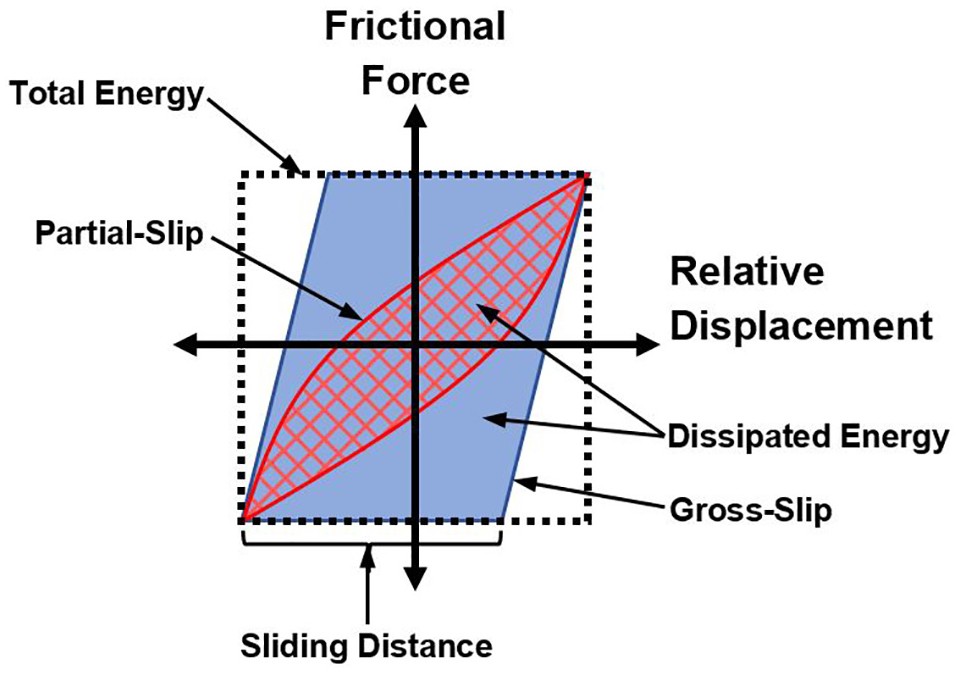
Example fretting loops for partial slip (red) and gross-slip (blue) regimes. Total energy is the area of the dotted region. Dissipated energy for the partial-slip and gross-slip fretting loops are the enclosed cross-hatched and light blue areas, respectively. The sliding distance for the gross-slip regime is highlighted.
Test parameters in a fretting test must be carefully selected to improve clinical relevance of the results. Test frequency and initial surface roughness could affect the slip regime. 66 A test frequency of 1 Hz is advisable to simulate the cyclic micromotion that occurs during gait. Aside from differences in the slip regime, surface roughness has also been found to significantly affect electrochemical performance in fretting tests. 67 Furthermore, the investigator must select clinically relevant relative displacement and applied load. As detailed in section 4 of this review, in vitro simulations have measured micromotions at the taper connection of up to 28.72 µm. 68 Similar displacements in fretting tests are recommended. Simulating micromotion at amplitudes of 20 µm is technically challenging due to test system compliance. Simulation at this level is within the partial-slip regime (energy ratio<0.2), 69 and thus includes both adhesive and abrasive fretting wear. In vitro studies executed at larger amplitudes and higher energy ratio may not be representative of in vivo fretting corrosion due to a transition to the gross-slip regime. Selection of the applied load is more challenging due to the complex stress distribution in taper connections10,70,71 and increasing contact stress following distal displacement of the head onto the trunnion due to the tapered geometry. Using a ball-on-flat type contact, the contact pressure may be estimated based on the Hertzian contact model. However, a flat-on-flat contact better represents the taper connection. 72 Flat-on-flat contact pressure is not easily calculated; therefore, the contact pressure must be estimated based on the wear scar of preliminary test samples. 67 Royhman et al. 67 found the contact pressure was highly sensitive to surface topography, with the addition of microgrooves increasing surface pressure by 25 times compared to the polished control. Therefore, it is recommended that the surface pressure is determined as part of study design validation and compared to that estimated within the taper connection (e.g. via finite element analysis) to establish clinical relevance. Test parameters including frequency, displacement amplitude, applied load and energy ratio must be reported and justified to allow comparison between studies and understanding of the clinical condition simulated.
An advantage of electrochemical studies is their relative simplicity and efficiency. As a consequence of the simplification, important mechanisms may be excluded from the study, limiting the result’s application. For example, Goldberg and Gilbert 25 found CoCr’s oxide layer was more resistant to fracture than Ti6Al4V (i.e. resistant to mechanical fretting) but Ti6Al4V had lower dissolution current over a wider range of sample potential (i.e. resistant to sample potential electrochemical affect). Therefore, both the mechanical and electrochemical aspect must be investigated. Results must be carefully interpreted in the greater context of the multifactorial head-neck taper connection tribocorrosion phenomenon. In 1997, Gilbert and Jacobs 4 proposed the mechanism of MACC and in 2015 he was first to report CAC. 5 Detailed theoretical frameworks for MACC and CAC’s initiation and progression have since been published.4,6
Electrochemical studies described earlier do not consider geometric or long-term effects. Potentiodynamic studies and Electrochemical Impedance Spectroscopy investigate intact samples at steady state, while studies investigating the oxide layer’s integrity observe the transient electrical activity. Neither use samples with geometry representative of prostheses, which has been identified as important to performance clinically. 8 Although local crevice corrosion effects have been observed around fretting damage in pin-on-disc electrochemical studies, 73 neither potentiodynamic or EIS studies reproduce the crevice geometry critical to the MACC phenomenon. A pin-on-disc or similar test apparatus allows particles generated during a fretting-corrosion simulation to escape the region of interest. Conversely, wear debris generated in vivo is captured within the taper connection and affects a range of tribocorrosion processes and factors including third body wear, microabrasion, lubrication and fluid flow. Although the crevice environmental conditions can be simulated manually, the way it develops may be an important property of a sample.
Royhman et al. 74 developed a fretting test with the aim of testing the fretting-corrosion behavior of hip implant taper connections. The test apparatus consists of a rectangular sample articulating against the circular face of two cylindrical pins, thus representing the fretting couple. The articulation occurs in an environmental chamber, where parameters such as applied potential, test solution, acidity and temperature are controlled. The advantage of such a system is the direct and precise control of a range of parameters relevant to the tribocorrosion process. Conversely, the disadvantage is that each of these parameters is set based on assumptions and estimates of the possible taper conditions in vivo. Nevertheless, this and similar test apparatus provide invaluable insight into components of the tribocorrosion process, but their design must be considered alongside other related evidence to determine clinical significance of the findings. Royhman et al. 72 tested all Ti6Al4V couples compared to those involving both Ti6Al4V and CoCr. Couples including CoCr operated within the gross-slip regime, perhaps due to the materials greater Young’s modulus and the material couple’s lower coefficient of friction. Gross-slippage indicates a greater susceptibility to fretting-corrosion compared to the all Ti6Al4V couple operating within the partial-slip regime, Consideration of the tribological behavior of different material couples is important, and may provide insight into the relative tribocorrosion performance of mixed and similar metal head-stem combinations. However, the finding is based on a test method where the applied load at the contact is constant between material couples, but differences in material stiffness could affect contact area and pressure such that the difference in fretting regime may not apply clinically. Royhman et al. 69 also estimated the relative contribution of corrosion and wear to the overall material loss by fretting-corrosion. Their calculation tended to overestimate the contribution of corrosion; however, it still resulted in wear dominated material loss. However, the calculation also assumed negligible contribution from CoCr alloy, based on their earlier finding that mass loss due to corrosion was 2 orders of magnitude greater with Ti6Al4V than CoCr. 74 However, a retrieval analysis of CoCr femoral heads with Ti6Al4V stems has shown greater damage of the CoCr heads. 18 Therefore, the clinical significance of dominant wear material loss in this in vitro study is not clear.
The relative degree of corrosion between materials cannot be determined by corrosion current’s magnitude due to differences in valence. The charge released per unit volume of oxide for Ti6Al4V alloy is approximately three times higher than that of CoCr alloy. 25 To determine the volume of wear, the researcher may perform weight change, volumetric change, or ionic analysis, as described herein with in vitro simulation type studies. Furthermore, although a material may be more susceptible to corrosion, its toxicity to the patient must be considered when determining clinical relevance.
Indicators of a corroding or worn prosthesis are particular to Co or Cr ions. MHRA, AAOS and Health Canada consensus75–77 is that patient blood Cobalt and Chromium ion levels >7 ppb may indicate a poor performing metal-on-metal prosthesis. However, the relationship between metal ion levels and clinical outcomes remains unclear. 78 Regardless, the particular material released is a more clinically relevant measure as opposed to gross current generated.
The sample environment is a key input to the electrochemical study. The environment may vary in composition and electrical potential. Environments may be controlled to generate a simulated crevice corrosion environment. Goldberg and Gilbert 61 investigated the effect of solution acidification, aeration and addition of proteins versus simple phosphate buffered saline on the repassivation of CoCr alloy. Changing the pH was found to affect the polarization curve, as might be expected considering the material’s Pourbaix diagram where Cobalt and Chromium move from the passivation to the corrosion domain at lower pH. 79 Kuprienko et al. 80 found there may be an optimal protein concentration for minimizing corrosion; therefore, the presence and concentration of protein are both important. Gilbert et al. performed a similar study to Goldberg et al., except they investigated Ti6Al4V alloy and also considered the effect of sample potential. They found significant effect of sample potential on peak currents and time constants on the transient repassivation behavior, 81 as may be expected considering the sample’s polarization curve. If the corrosion environment is instead allowed to develop naturally as in an in vitro simulation, the process must not be interrupted. Bhalekar et al. 82 performed a taper wear study that required periodic disassembly of components for weight loss measurement. Higher mechanical than corrosive damage was noted in this study, perhaps because the corrosive crevice environment was not allowed to develop.
In vitro studies often exclude biological effects by selecting PBS41,83,84 or bovine serum82,85 test environments. Brown and Merritt 86 found a 10 fold reduction in fretting-corrosion with calf serum in saline over saline only solution. Gilbert et al. 5 showed a 40–100 fold increase in corrosion susceptibility when the test environment was modified to represent the chemistry under inflammatory cells. Bijukumar et al. 6 have demonstrated the possible role of macrophages in the taper corrosion process. It has been suggested that exclusion of biological effects may be why certain in vitro studies do not replicate all damage modes experienced in vivo, such as etching, intergranular corrosion and phase boundary corrosion. 6 The cell assisted corrosion process is the subject of continued research and refinement. 87 Identifying patient factors associated with this biological response may help in preventing trunnionosis in at risk populations.
In vitro simulation
When confronted with the limitations of simplified electrochemical studies, a complex in vitro simulation may be required. In vitro simulations share many of the advantages, disadvantages and procedural considerations as other electrochemical studies. However, as a more accurate representation of the in vivo mechanism, there may be greater confidence in the clinical application of results from a well-designed study. In addition to the test considerations presented for other electrochemical studies, invitro simulations also require decisions regarding sample assembly and test loading conditions. Assembling components dry with high impact loads have been shown to reduce the resistance to tribocorrosion in short term in vitro simulation 88 and less conclusively at longer term. 41 Assembly is often simulated using a ramping load to 2kN in accordance with ISO standard recommendations. 89 However, light assembly by hand or high impaction load (up to 8 kN has been reported 88 ) may be more relevant depending on surgical technique. In vitro simulation has a unique advantage to investigate parameters like assembly load which are not included in data subject to clinical or retrieval studies.
Taper disassembly strength is an often-reported attribute; however, it is not indicative of the more complex tribocorrosion phenomenon. At best, taper connection disassembly strength is an indicator of a taper connection geometry’s resistance to fretting, where disassembly strength is a surrogate for connection stability and fretting related micromotion. Disassembly strength does not account for differences in corrosion properties between materials. Rehmer et al. 34 found that CoCr heads had a lower disassembly strength when used with CoCr stems compared to Ti6Al4V; however, this finding opposes Collier et al. 60 who found less corrosion evidence with CoCr-CoCr head-stem combinations compared to CoCr-Ti6Al4V. Jauch et al. 36 measured fretting-corrosion currents at loads below the disassembly load, further demonstrating the disconnect between the two measures. Other important factors such as crevice geometry, sample potential, repassivation kinetics, surface abrasion, micromotion mechanics and fluid flow are similarly discounted if disassembly strength alone is considered.
The mechanical aspect of the head-neck taper connection tribocorrosion process depends on the applied load. Each of the type (axial vs torsional), magnitude, and frequency of loading may impact behavior. The standard for fretting-corrosion testing of modular hip replacement prostheses’ head-neck connection requires only axial compressive loading. 40 However, torsional loading has been shown to initiate fretting-corrosion at clinically relevant levels,36,47 particularly under adverse conditions such as edge loading or third body abrasion. Higher magnitude loading increases fretting-corrosion by producing larger and deeper scratches, thus exposing greater material to corrosive attack. 61 Loads ranging from 1500 to 5340 N have been employed.83,90 At the upper extreme, 5340 N represents worst case repetitive loading of the femoral head over its lifetime, as per ISO standard testing of hip replacement components. 91 A load based on simulated gait may be more appropriate. A 1 Hz sinusoidal load may not approximate a 1 Hz gait cycle. During gait, a double peak load waveform is experienced, as detailed in the Paul curve. 92 To coincide with the periodicity of these peaks, a 2.4 Hz sine curve is most appropriate. 93 This may be impractically slow to simulate longer implant usage. The electrical activity related to oxide fracture and repassivation has been noted at frequencies up to 10 Hz, 93 as expected considering the near instantaneous repassivation of common implant alloys.25,61,81 But high rates may impact fluid flow and thus the crevice corrosion environment. 41 The ASTM standard for fretting-corrosion of modular implant interfaces recommends test frequencies below 5 Hz. 40
Micromotion at the taper connection plays a critical role in tribological wear and mechanically assisted crevice corrosion. 7 Methods for measuring micromotion during in vitro simulation vary in their accuracy and degrees of freedom. A single linear variable differential transformer (LVDT) may be used to measure displacement along a single axis. 41 To do so, the body and core of the LVDT are fixed to the head and stem, respectively. Pistoning type micromotion can be measured if the LVDT’s piston is aligned with the taper’s axis. However, a single LVDT cannot measure motion in multiple degrees of freedom. An array of sensors allows analysis of multiple degrees of freedom. Haschke et al. 56 fixed an apparatus with six differential variable reluctance transducers (DVRTs) to the femoral head and neck to allow micromotion measurement in 6 degrees of freedom. Micromotion at the taper connection surfaces is calculated from the DVRT measurements by a coordinates transformation assuming a rigid body between the sensors and taper connection surface. The rigid body assumption is made on the basis that elastic deformations are determined and subtracted from the overall measurement. The elastic deformation may be found by measuring displacements during testing with a monoblock 68 or “near” monoblock sample. A “near” monoblock sample may be prepared by assembling the head onto the stem with a very high load such that taper connection micromotion is considered negligible. 56 Alternatively, elastic deformation may be calculated by finite element analysis. 56 The authors are not aware of any non-destructive method to directly measure taper connection surface micromotion.
An optical method involving destructive means of micromotion measurement is demonstrated by Falkenberg et al. 55 By the optical method, two holes are made in the femoral head allowing view of the stem’s trunnion. To minimize the effect of the holes on the contact mechanics, small holes are produced without burrs by electric discharge machining at locations outside the theoretical taper engagement area. Images of the trunnion are taken by a laser scanning microscope through the holes during loading, and image analysis software is used to overlay subsequent images and calculate micromotion. The advantage of direct measurement by this method is at the expense of some limitations. The optical method allows direct measurement only in the plane of the 2D image, while an array of DVRTs allows measurement in all 6 spatial degrees of freedom 56 (Figure 3). If the sample and load are symmetric about the imaging plane, displacements aside from those measured from the 2D image may be insignificant. To determine micromotion aside from those in the 2D image, a finite element model may be validated and used. 55 Holes in the femoral head modify the natural fluid mechanics in the taper connection; therefore, testing with the optical method can only be performed dry. Conversely, submersible DVRTs can be used to measure micromotion simultaneously with electrochemical measurements in an environmental chamber. 94 The destructive nature of the eroded holes into the femoral head also introduces an uncertain impact on the contact mechanics. In terms of the measurement accuracy necessary, in vitro studies have previously reported micromotion displacements in the range of 0.01–28.72 µm41,55,56,68,94 or rotations of 0.003°–0.022°. 56 Vibrations of the loading machine may be comparable magnitude to the micromotion of interest 41 and may need to be controlled. Retrieval studies have reported fretting scars as short as 5 µm in length 95 ; therefore, the clinical relevance of smaller micromotions is unclear.
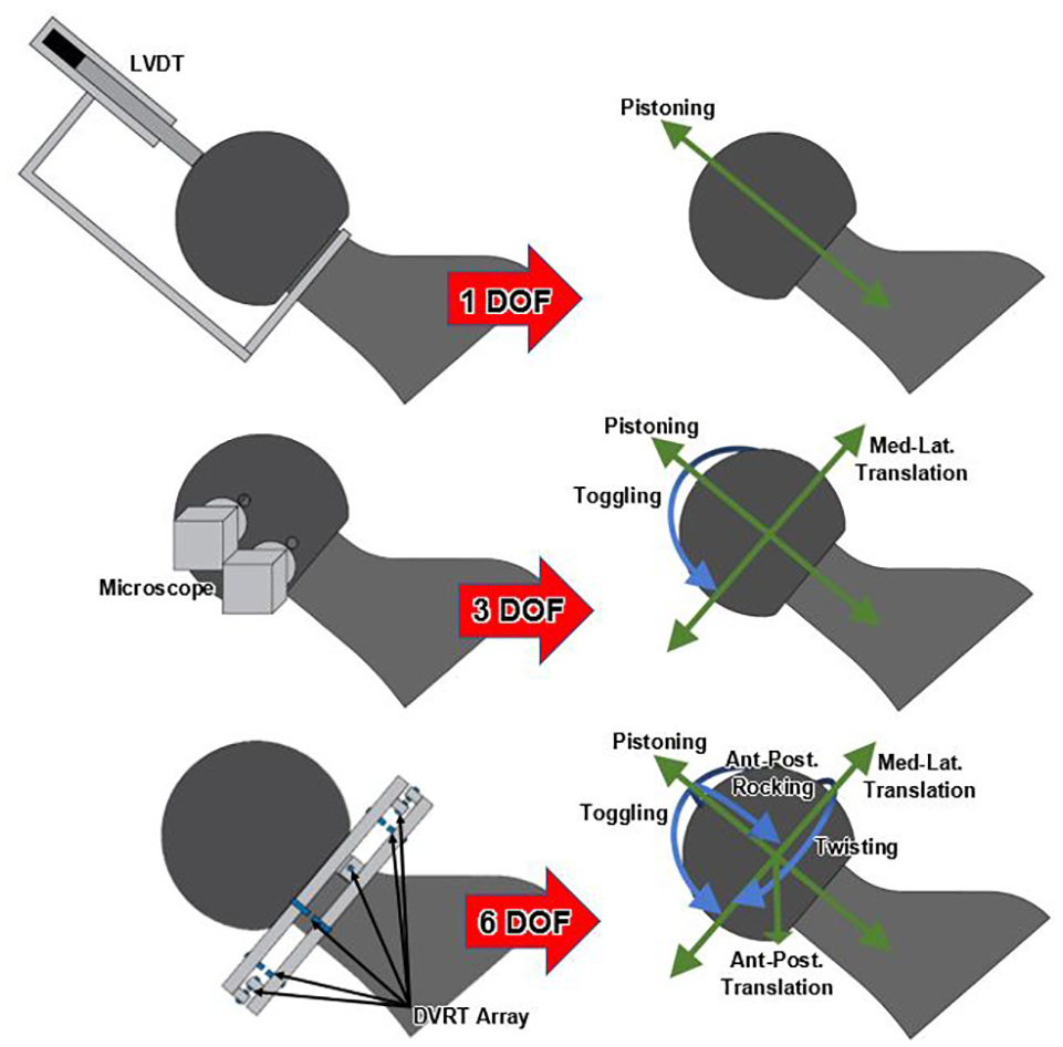
Degrees of freedom from a single LVDT (top), image analysis (middle) and DVRT array (bottom).
In addition to the electrical measurements discussed herein for other electrochemical studies, in vitro simulations allow measurement of fretting-corrosion onset load and wear. Fretting-corrosion onset load is the minimum load at which fretting-corrosion occurs, as determined by incrementally increasing the peak cyclic load, and identifying the minimum load where OCP and corrosion current shift from baseline. 25 Fretting-corrosion onset load is a powerful measure because it allows a degree of comparison between materials, unlike other measures often used in electrochemical studies as described earlier. However, since fretting-corrosion onset load indicates only the initiation of the phenomenon, long term tests may find differences between samples (including material performance) unanticipated based on onset load alone. For example, Goldberg and Gilbert 96 found similar onset loads for similar and mixed alloy headstem combinations, but in their earlier retrieval study found greater tribocorrosion with mixed alloy implants, 18 demonstrating the taper connection’s initial resistance to corrosion onset is not necessarily indicative of in vivo performance.
Wear is an important measure since it is the wear debris that ultimately causes adverse reactions. Wear may be measured many ways. Visual inspection may qualitatively assess wear, identifying the corrosion mechanisms. Goldberg et al. 18 developed a semi-quantitative scoring rubric used to assess corrosion from images based on the area and severity of fretting and corrosion. This method is often used when assessing retrieved components but can be used with samples following long term cyclic loading in vitro. Knutsen et al. 97 demonstrated the utility of the Goldberg scale by identifying a low but significant correlation with histological scores of adjacent tissue. Hothi et al. 22 found the Goldberg corrosion scores to have good inter-observer reproducibility and single observer repeatability, but fretting scores were more difficult due to being masked by corrosion discoloration, or otherwise missed on low magnification images. Automated image analysis algorithms have been developed to more objectively apply Goldberg’s scoring criteria. 98 Higgs et al. 99 have proposed a similar scoring rubric.
Quantitatively, wear can be measured by weight change, ionic analysis or direct measurement of the component’s geometry. Weight change following cycling is the simplest measure but provides no other useful information since the wear pattern is not identified. Ionic analysis can similarly estimate the total wear mass and gives further information about its composition. Estimating wear mass by ionic analysis is technically challenging. The investigator must consider the varied ionic composition of the test solution between the bulk solution and that in the crevice. 41 Furthermore, debris adherent to the sample must also be considered. Test solution contamination may also be inadvertently measured as wear debris. Wear volume is often measured by calculating the volumetric change in pre- and post- test measurements taken by CMM49,100 or similar equipment.101,102 In addition to measuring the total wear volume, this method provides qualitative information on the connection mechanics. One example is the difference seen in wear patterns on neutral versus high offset femoral heads, which tend to piston or rock, respectively. 49 Wear measurements are a robust measure for comparing samples; however, in the case of differing materials their respective toxicity must be considered.
Conclusion
Many in vitro test methods fall short in replicating the mechanism they aim to investigate. FE analyses offer an efficient way to investigate mechanical parameters; however, at the expense of electrochemical, biological and fluid flow factors. Where these factors are to be considered, researchers rely on electrochemical studies. Invitro studies inherently involve assumptions and simplifications, the consequences of which must be fully understood by the study designer and data reviewer to avoid false and potentially conflicting conclusions. Complex in vitro simulations have been developed; however, they remain incomplete in replicating the taper connection’s clinical failure process. This review is limited to the review of in vitro test methods investigating tribocorrosion at the head-neck taper connection. In vivo test methods such as cohort studies and retrieval analyses play an important role in the body of research relevant to taper connection tribocorrosion, and they have their own advantages and disadvantages. In vitro test method considerations presented in this review may not be directly applied to modular connections outside of the femoral headneck taper connection in total hip replacement prostheses.
Continued work is necessary to address the limitations of in vitro test methods identified in this review to improve translation of their findings to clinical practice. Advancement of computational modeling techniques to improve consideration of electrochemical, biological, and fluid flow factors may allow more accurate representation beyond mechanical factors. Computational modeling of micro-level contact mechanics, surface material properties and the evolution of parameters after a period of simulated use offer further opportunities for advancement. The most complex in vitro head-neck taper connection tribocorrosion simulations remain incomplete in replicating the in vivo process. Contribution to tribocorrosion of biological factors remains poorly understood and limits the ability to simulate biological effects. Further investigation into the biological response to tribocorrosion debris and the role of biological factors may allow development of a more complete in vitro simulation. Some test methods are limited by their nature. For example, static electrochemical studies do not consider dynamic processes and fretting tests do not consider sample geometry. Advancement within these methods requires clear reporting and justification of the test parameters as well as identification of limitations. Conclusions must be drawn within the limitations of the test method.
Regardless of in vitro test method, there is an absence of suitable standardization across test apparatus, methodologies and analysis techniques. As a result, it is difficult to aggregate and interpret findings from highly varied studies. Generation of standard test methods, including validation techniques, limitations and reporting requirements, derived from current knowledge by a multidisciplinary group of experts would focus the research community’s efforts toward minimization of tribocorrosion related adverse patient outcomes.
Footnotes
Declaration of conflicting interests
The author(s) declared no potential conflicts of interest with respect to the research, authorship, and/or publication of this article.
Funding
The author(s) received no financial support for the research, authorship, and/or publication of this article.