
Abstract
In recent years, steerable catheters have been developed to combat the effects of the dynamic cardiac environment. Mechanically actuated steerable catheters appear the most in the clinical setting; however, they are bound to a number of mechanical limitations. The aim of this research is to gain insight in these limitations and use this information to develop a new prototype of a catheter with increased steerability. The main limitations in mechanically steerable catheters are identified and analysed, after which requirements and solutions are defined to design a multi-steerable catheter. Finally, a prototype is built and a proof-of-concept test is carried out to analyse the steering functions. The mechanical analysis results in the identification of five limitations: (1) low torsion, (2) shaft shortening, (3) high unpredictable friction, (4) coupled tip-shaft movements, and (5) complex cardiac environment. Solutions are found to each of the limitations and result in the design of a novel multi-steerable catheter with four degrees of freedom. A prototype is developed which allows the dual-segmented tip to be steered over multiple planes and in multiple directions, allowing a range of complex motions including S-shaped curves and circular movements. A detailed analysis of limitations underlying mechanically steerable catheters has led to a new design for a multi-steerable catheter for complex cardiac interventions. The four integrated degrees of freedom provide a high variability of tip directions, and repetition of the bending angle is relatively simple and reliable. The ability to steer inside the heart with a variety of complex shaped curves may potentially change conventional approaches in interventional cardiology towards more patient-specific and lower complexity procedures. Future directions are headed towards further design optimizations and the experimental validation of the prototype.
Keywords
Introduction
State-of-the-art in steerable catheters
The use of catheters in interventional cardiology has become inevitable for successful treatment of cardiac patients. As such, a large variety in catheter sizes, functions, and configurations are available, ranging from simple delivery tubes to more complex types with added functionality.
Despite these developments, precise positioning of the catheter tip inside the heart remains one of the main challenges in interventional cardiology due to the heart’s dynamic and complex three-dimensional (3D) environment.1,2 As such, mal-positioning of catheters and interventional tools is reported as a frequent problematic event in multiple procedures and may, depending on the intervention, lead to insufficient placement of cardiovascular implants (e.g. trans-catheter heart valve implantation), cardiac perforation, incorrect path ablation, or even heart rhythm disturbances.3–6
To prevent adverse events and improve clinical outcomes, a large number of design concepts (>800) for steerable catheters have been patented. 7 Besides the regular push/pull and torque movements, steerable catheters may have additional degrees of freedom (DOFs), and one or more deflectable segments in the tip that have been designed to allow the interventionist to navigate in tortuous vasculature, steer through tight curves, access hard-to-reach sites (including the left side of the heart through the atrial septum), reach over sensitive structures, and precisely position the tip. In addition, steerable catheters eliminate the need to change out multiple sheaths or introducers, especially during complex procedures.
As of today, from all patented concepts, a small number of steerable catheter systems are commercially available, including, but not limited to, the following: the Niobe Magnetic Navigation System (Stereotaxis, St. Louis, MO, USA) is one such system that uses magnetic actuation to navigate the tip position.8–10 Another system is the Artisan Control Catheter that is used together with the Sensei Robotic System to provide robotic catheter control (Hansen Medical, Mountain View, CA, USA).8,11 The Agilis™NxT (St. Jude Medical, St. Paul, MN, USA) is a steerable sheath, mainly used during mapping and ablation procedures in electrophysiology, and provides bidirectional steering with two asymmetric curves. 12 Finally, the CPS Venture™ (St. Jude Medical) catheter is mainly used during coronary and peripheral interventional procedures as a one-directional steerable catheter. 13
Comparative studies of steerable catheters
Previous clinical studies have focused on the comparison between steerable and non-steerable catheters and sheaths in various cardiac procedures. The use of steerable catheters and sheaths has shown to significantly improve procedure time and patient safety in a number of comparative clinical trials.14–16
Nounou et al. 17 reported the use of an 8.5-Fr steerable Agilis guide sheath to ensure correct positioning of an Amplatzer closure device in an adult patient having an atrial septal defect. The steerable sheath with adjustable curve allowed for easy positioning of the guiding catheter and resulted in a successful procedure. More recently, Tiroch et al. 18 reported a case in which a novel mitral clipping technique was combined with the steerable guide sheath that is part of the MitraClip system. The procedure relied on two alternating 90° bends of the steerable sheath, allowing the clinicians to advance the clip delivery system further in the steerable guide and position and align it into an adequate grasping position. Piorkowski et al. 19 studied the use of steerable (Agilis) versus non-steerable sheaths during left atrial (LA) fibrillation ablation in 130 patients. The randomized controlled trial proved single procedure success to be significantly higher in patients ablated with a steerable sheath as compared to treatment with a non-steerable sheath (76% versus 53% after 6 months, p = 0.008). The study demonstrated that using a steerable sheath results in significantly better rhythm control of the ablation catheter when compared to using a non-steerable sheath during ablation. 11
In multiple other studies, the use of steerable catheters and sheaths allowed for successful treatment of patients who could otherwise not be treated by a standard approach with a non-steerable catheter.12,20,21
Remaining limitations
Despite the available steerable catheter systems and the generally positive clinical outcomes so far, their use in the clinical setting remains subject to various downfalls. In particular, even though robotic and magnetic systems offer relevant possibilities in steering, they require major investment and generally a different operating room and update of operating skills. 21
Mechanically actuated catheters do not require such major changes as their steering technology is located inside the catheter and handle and is based on the relatively simple use and mechanical actuation of steering cables. However, the current steering potential of mechanically actuated catheters is limited. Typically, they use push/pull deflection wires that actuate the steerable segment. A number of general limitations occur in different catheter types, regardless of their level of steerability, as a result of co-play between catheter components with each other as well as with the tortuous vasculature and dynamic cardiac environment. Some effects are the result of torque and push force application,22,23 whereas others are influenced by the cable actuation and material choice, 24 or internal friction between the catheter and the cables. These effects further complicate steering.
In addition to the aforementioned limitations, a number of clinical challenges arise as a result of the dynamic cardiovascular environment. The movement of catheters inside the vasculature is, for example, linked to increased vascular damage.25,26 With sheaths and catheters being rotated inside the vasculature or being exchanged for catheters with different sizes or functions, arrhythmias and damage to vessels or sensitive structures are some of the most frequently occurring complications. 27 Moreover, the current limited amount of steering in mechanically actuated catheters does not allow for complex or multiple curves to be made inside the heart. For example, following a circular pattern during pulmonary vein (PV) isolation or safely bending the catheter tip in an S-shaped curve after atrial septum entry are currently nearly impossible tasks.28,29
As such, there remains a clinical need for mechanically steerable catheters that are more reliable in their mechanical behaviour, require less frequent exchange of different catheters, and allow more complex tip shapes and motions in terms of steering.
Study aims and paper layout
The future generation of catheters must allow for successful manipulation during complex procedures inside the heart without being hindered by mechanical or clinical limitations. By analysing these limitations and increasing the steerability in terms of adding more DOFs, a first step can be made in the direction of improved catheter behaviour. As such, this research has two aims. The first aim is to provide insight in the mechanical behaviour and limitations of currently existing mechanically actuated steerable catheters. The second aim is to use the gained insight to develop a new steerable catheter prototype that is able to steer in multiple planes and directions, improving catheter manoeuvring potential for complex cardiac procedures. As such, section ‘Mechanical analysis’ presents a mechanical analysis of current steerable catheters, focusing on the limitations. Section ‘Prototype design’ describes the prototype design of the new steerable catheter, and section ‘Proof-of-concept test’ focuses on a proof-of-concept test. The final results are discussed in section ‘Discussion’ followed by the conclusion.
Mechanical analysis
Overview
In previous research, we analysed the underlying steering mechanisms in steerable catheters and developed a structured classification of the technical possibilities. 7 In this study, we will break apart the inefficient steering into five limiting factors: (1) low torsion, (2) shaft shortening, (3) high unpredictable friction, (4) coupled tip-shaft movements, and (5) complex cardiac environment. Figure 1 shows an overview of each of the five limitations, along with their resulting clinical effects, and the underlying reason of each limitation based on the mechanical analysis. The contents of Figure 1 will be discussed in the following sections.
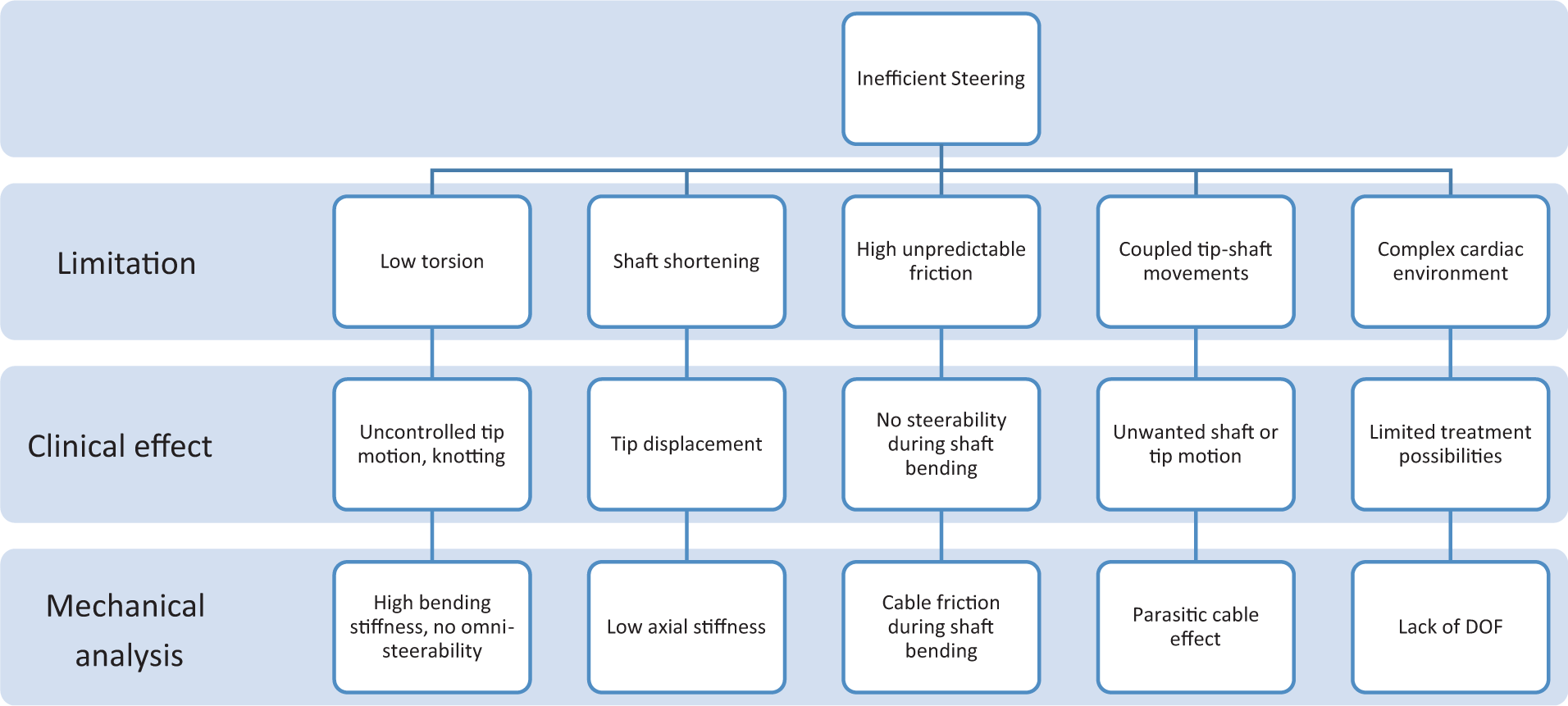
Mechanical analysis scheme.
To provide insight in steering possibilities with mechanically actuated catheters, three levels of steerability are described in terms of gradual DOF increase.
1 DOF: single plane
The simplest steering possibility for a mechanical catheter consists of one spring-like construction with one or two steering cables fixed at the tip, providing a 1-DOF tip deflection in one or two directions in a single plane, see Figure 2(a). Most commercially available mechanically steerable catheters are of this type.
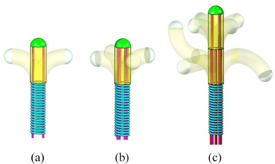
Three steering possibilities of mechanically steerable catheters with (a) 1-DOF steering with one steerable segment, (b) 2-DOF steering with one steerable segment, and (c) 4-DOF steering with two steerable segments.
2 DOF: multiple planes
An increase in DOF leads to the possibility of omnidirectional steering in which the catheter tip is able to bend in two planes perpendicular to each other, Figure 2(b). This method allows for steering without having to axially rotate the entire catheter shaft inside the body. This strongly simplifies the steerability for the surgeon and allows for procedures with increased level of complexity. There are no known commercially available mechanical catheters of this type.
Multi-DOF: multiple simultaneous planes
The last possibility is that of multi-steering, in which multiple stacked tip segments are used that each allow omnidirectional steering. Such a system will not only allow improved steering in reaching the end-point target but will additionally allow shape control along the pathway. Following tortuous pathways in the vessels, making S-shaped curves inside the heart, and creating multi-planar movements are examples of the new possibilities, Figure 2(c). There are no known commercially available mechanical catheters of this type.
As a first step towards such multi-DOF catheters, it is required that all mechanical limitations are solved, after which the requirement for increased steerability can be met. In the following section, the mechanical limitations will be discussed for the currently existing catheter types.
Low torsion
Mechanical limitation
The limitation of low torsion is generally apparent when the clinician wishes to direct the catheter tip in a different direction once placed inside the body. A 1-DOF steerable catheter will not be able to bend the tip in all possible directions, and torque is therefore applied to the catheter shaft to overcome the vascular friction and change the direction of the tip. 30 In addition, push–pull movements are applied to push the catheter forward inside the patient. Upon applying torque on a straight shaft, only the friction with the vessel wall has to be overcome. However, when a bent shaft is used to transmit torque from handle to catheter tip, the bending stiffness of the shaft starts playing a role too. 31 In general, materials with high bending stiffness are preferred for catheters, because they maintain high pushability. Consequently, when applying torque to twist the catheter inside a vascular vessel, the high bending stiffness causes increased friction with the vessel wall, resulting in typical torque-related complications such as shock-wise, uncontrollable, or unreliable tip motion and positioning.24,25 In theory, how well the catheter will reply to torsion depends on a ratio between bending stiffness and torsion stiffness. Ideally, each rotation at the shaft or handle end is identical to that of the tip. 12
Clinical effect
Multiple studies have shown that torque-related complications can result in an unpredictable dislocation of the tip from its intended position, leading to injury of surrounding tissue, or perforate delicate structures. Selective coronary arteriography in children, for example, requires precise catheter positioning inside the vessel orifice. When the applied torsional force pushes the catheter against the vessel wall or pushes it too deep inside the vessel, it can cause coronary spasm or intimal injury.31–35 Tanner and Ward 23 described five cases in which torque application during a cardiac catheterization procedure led to a knotted catheter inside the patient. The knots caused resistance during withdrawal and had to be solved first before the catheter could be removed. Knotting is a recognized complication and generally the result of excessive torque.22,36 Finding a solution for the underlying reason to apply torque, for example, by using a 2-DOF steerable tip, can negate the torque-related difficulties.
Shaft shortening
Mechanical limitation
Shaft shortening is encountered as an effect of steering when the movement at the handle part is not fully transferred to the tip. Even though catheter material properties have improved, the used spring-like materials still often result in a shortening of the shaft during steering. Because shafts of steerable catheters generally consist of multiple layers of braided or coiled spring-like structures, the shafts will have a relatively low axial stiffness. As a result of the shaft compressibility, energy that is applied at the handle is not fully transferred to the tip, resulting in a decreased tip movement.
Clinical effect
A shaft shortening limitation was first described by Kelly and Boyd 24 in a study focusing on the buckling of a tethering catheter during implantation of a temporary caval filter. Even though the shaft shortening in this study was the result of catheter buckling and not of axial compression of catheter materials, both lead to similar clinical consequences. Kelly’s catheter shortening and the resulting shaft curves forming inside the cardiac cavities led to incorrect positioning of the tip and to filter migration to the right atrium in multiple patients. Finding a method to develop an incompressible shaft is therefore still a topic for research.
High unpredictable friction
Mechanical limitation
High or unpredictable friction between catheter sleeve and actuation cables is observed once the shaft is placed in a bend and when the catheter is steered. Even though effort has been put in studying friction between outer catheter surface and inner cardiovascular surface,37–39 no references have been found on the effects of friction inside the catheter itself. Once the catheter is placed in a bend or curve, increased normal forces between cable and guide can cause high friction forces, and altogether an increase in the required steering forces at the handle. In some cases, the catheter is prevented from reaching its full theoretical bending potential, while in other cases, the steering is inhibited due to a blocked tip motion.
Clinical effect
High, unpredictable friction makes it difficult for the interventionist to predict what amount of steering force should be used during each condition. In addition, when high steering forces are required to create the bending motion, the forces on the cables can exceed their maximum tensile strength, causing them to plastically deform or break. To prevent these effects from happening, it is important that the friction inside the mechanism is either minimized, conditioned to a constant value, or made somehow predictable.
Coupled tip-shaft movements
Mechanical limitation
Coupled tip-shaft movements occur when the cable part running through the shaft experiences tension upon tip actuation and moves to actuate the shaft as well, causing unwanted changes in the curvature of the shaft. The opposite effect, in which the shaft unintentionally contacts tissue, causing an unwanted actuation of the tip, can be observed too.
Clinical effect
From a clinical perspective, coupled tip-shaft movements lead to a dislocation of the tip from its intended position and orientation, which is undesired. Even though the phenomenon has not been studied extensively, Avitall et al. 40 studied differences between non-deflected and maximally deflected catheter states and found that a decreased tip deflection occurs when the catheter shaft is bent or twisted. Once the shaft is placed in one or multiple curves, the tip motion is not only decreased, but its position is dislocated as well in reference to the position it had when the shaft was straight. To prevent these effects, it is important to strive for steerable catheter designs which inherently avoid tip-shaft coupling.
Complex cardiac environment
With the previously discussed mechanical limitations that complicate steering in general, it becomes a complex and demanding task to use the catheters to steer in an active cardiac environment. Figure 3 shows blood flow and cardiac movements as well as instrumental movements in different directions, represented by arrows. In addition, the majority of existing mechanically steerable catheters only provide single-plane 1-DOF steering. Multiple curves with different reaches and angles, S-shaped curves, and multi-planar curves are some of the examples that are preferred in a single adjustable catheter.8,13,41 Up to now, there is no such system available that allows all these steering functions in a mechanically controlled and reliable manner. 7 To allow for improved steering functions, all aforementioned limitations need to be solved and a method to add additional DOFs must be found.
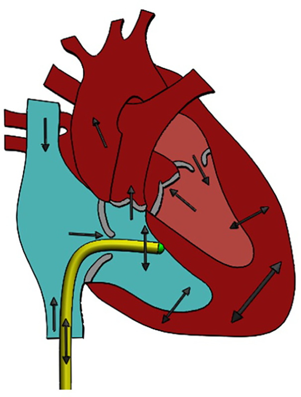
The effect of the cardiac environment on catheter movement including tight curves, tortuous vessels, blood flow, beating and breathing motion, weak or calcified structures, and complex three-dimensional shapes.
Prototype design
Requirements and clinical application
In this research, we decided to design a multi-steerable catheter that is suited for steering inside the heart. The design will not yet be designed for a single specific procedure which would require additional functions, such as for valve replacement, cardiac ablation, or myocardial biopsy. The design that will be presented is a multi-steerable catheter with a central lumen and can be used either as a guiding sheath or as a catheter design to which future procedure-related functions can be added.
Functionality-wise, we decided to develop a catheter with two steerable 2-DOF segments. The total of 4 DOF was chosen to enable multi-directional and multi-planar curves, as well as S-shaped curves. It must be possible to actuate each of the segments independently and to remain in the chosen curve when required. We therefore decided to equip the catheter with independent steering and shape locking for each of the two segments.
The dimensions were set as follows: the tip must have a length of 4 cm, which will be long enough to manoeuvre in each atrium or ventricle of the human heart in every beating condition. The length of the shaft will be 1 m, long enough to test the functionality of a first prototype. The overall outer diameter of tip and shaft must be no larger than 3 mm, which is equal to or smaller than commercially available guide sheaths but larger or equal to commonly used catheters. A lumen of 1.5 mm must be present for future research purposes to allow for incorporation of fibres or cables.
In order to actively steer the catheter tip, we decided for a hand-held handle for single-hand use. We decided to control the two segments with two independently manoeuvrable omnidirectional joysticks on the handle – one to be controlled by the thumb and the other to be controlled by the index finger. We decided for a design in which the joysticks are automatically locked in position when they are not being touched, which will lock the shape of the catheter tip in position when the surgeon removes his or her thumb and finger from the joysticks.
Finally, we decided for a shaft design resistant against shortening and without a need for high torsion stiffness as twisting the shaft will not be used in our design for steering the tip – this will be done by controlling the omnidirectional joysticks. High friction inside the system must be prevented or conditioned to a constant, and the movement between tip and shaft must be uncoupled such that movement of one does not influence the other.
Tackling the mechanical limitations
In order to solve the shaft shortening issue, we investigated two different solutions. In the first option, we studied the use of a segmented shaft. With this solution, the axial stiffness can be increased by replacing the entire flexible shaft with a series of incompressible segmented elements. Segmentation of the shaft can be reached using various methods such as multiple different joint mechanisms, or metal or polymeric tubes with cut-outs to create elastic hinges. However, disadvantages are more complex miniaturization and manufacturing. In the second option, we studied the use of incompressible springs serving as Bowden cables. This is a simpler alternative for a segmented shaft and makes use of a closed tension spring or helical hollow strand (HHS) tube to compensate for the axial compression, combining easy bending with axial incompressibility. 42 In our design, we decided for a Bowden cable construction in which each steering cable is surrounded by a miniature closed tension spring with a pitch that is equal to the wire diameter, making the spring incompressible. The Bowden cables are used over the entire length of the shaft, resulting in an incompressible shaft that does not suffer from shortening.
In order to solve the limitation of the friction forces inside the catheter, a number of solutions were combined. The catheter tip was designed to have a very low bending stiffness by using a hinged segmented construction. The very low bending stiffness leads to less required force to bend the tip and therefore less force on the steering cables resulting in lower normal forces within the tip segments and the Bowden cables that could cause friction. In addition, the cables have been placed on the largest possible diameter in the tip to allow for a larger moment arm and therefore less required steering force. Finally, the use of Bowden cables allows for smooth guidance of the cables, leading to a low friction without stiction.
In order to reduce coupled tip-shaft movements when steering, the Bowden cables form an integrated solution. By guiding each steering cable through its own incompressible tension spring, each steering cable gets its own neutral line and is decoupled from the others. As a result, tip motion is decoupled from shaft position and shape, preventing any ‘parasitic’ moments in the shaft as the tip is steered.
Tip design
For the benefit of multi-steerability, the tip was created from two segments, each segment consisting of a stack of multiple steering elements ensuring smooth motion of the cables. For the purpose of convenience from here on, the most distal segment will be called Segment 1, and the proximal segment, Segment 2. Each segment is controlled by four steering cables. The four steering cables of Segment 1 are guided through four miniature Bowden cables that are fixed to the end point of Segment 2. Similarly, the four steering cables of Segment 2 are guided through four miniature Bowden cables that are fixed at the connecting point between tip and shaft. Using this Bowden cable construction, Segment 1 can be steered independently from Segment 2. The entire tip consists of a total of 17 stainless steel parts with an overall length of 40 mm, a diameter of 3 mm, and inner lumen of 1.5 mm. Figure 4 shows an overview of all numbered parts. Part 1 is the cable fixation component of Segment 1 and contains four grooves to enclose and attach the four steering cables of Segment 1 by means of glue. Parts 2–8 are the steering elements of Segment 1. These elements guide and hold the steering cables through bores running between their inner lumen and the outer wall. For smooth guidance of the steering cables, each two steering elements can make a maximum angle of 25° with respect to the neighbouring elements, all together adding up to a curve angle of 100° in each direction when the segment is actuated. In order to allow bending in each direction, each steering element has a single DOF and is designed such that its pivoting points are turned over 100° relative to the previous and following steering elements. In order to avoid sideways shifting of the pivoting points which could result in the segment to fall apart, the steering cables run through a bore in the centre of each pivoting point, creating a stable construction with precisely positioned joints. Part 9 forms the connection between both segments and is the cable fixation component of Segment 2, similar to Part 1, as well as the connection point for the four miniature Bowden cables of Segment 1. Parts 10–16 are the steering elements of Segment 2 and similar to Parts 2–8, but with four additional larger bores to guide the Bowden cables of Segment 1. Finally, Part 17 is the connecting component between tip and shaft in which also the four Bowden cables of Segment 2 are fixed, altogether leading to eight miniature Bowden cables that are guided into the shaft.
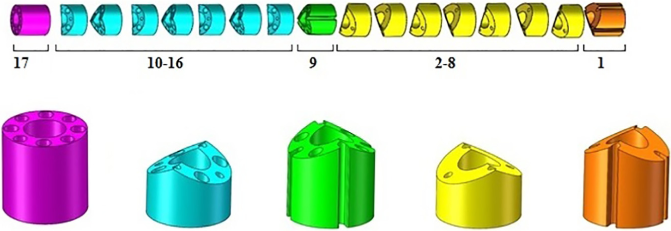
Segments and parts of the catheter tip, all manufactured from Stainless Steel 316.
Shaft design
The shaft has a relatively simple construction and consists of only 10 components: the eight Bowden cables, a tube for the inner lumen, and a sleeve that covers the entire construction. The Bowden cables are stainless steel springs with 0.3-mm inner diameter and 0.5-mm outer diameter, with each having a stainless steel steering cable running through the inside (0.2 mm diameter). The inner lumen is a reinforced Polyamide tube (Vention Medical, Salem, NH, USA). The lumen adds some stiffness to the construction and allows easier passage of a guidewire or another instrument through the catheter without interfering with the cables. The sleeve (Heat shrink tubing, Vention Medical) is passed over the entire construction, with the purpose of keeping all shaft components together, pushing the shaft through vessels, and protecting the blood vessel structure.
Joystick, handle, and prototype
For the purpose of steering the catheter tip, two joysticks were designed; one for each of the steerable segments. This allows the segments to be actuated independently from each other and also simultaneously. Each joystick consists of 14 components (8 different components) in total. The working principle of both joysticks is based on a rotating ball in a socket mechanism, see Figure 5. The largest visible part at the outer surface is a brass cylindrical cover covering all the internal parts and maintaining a specified distance between the top and bottom of the joystick. The cylindrical cover has an inner shape formed as a socket to house the ball joint to which the joystick is connected. The ball joint has been designed as a half sphere that is hollow from the inside. The joystick contains two baseplates. The first baseplate is connected to the bottom of the ball joint and serves as an attachment point for the four steering cables. The second baseplate is connected to the bottom of the joystick and serves as an attachment point for the four Bowden cables through which the steering cables are guided. In between the two baseplates, a compression spring was added that pushes the ball joint into the socket and creates friction between ball joint and socket when the joystick is released, thus locking the position of the ball joint and the corresponding bent of the catheter tip. The spring force can be adjusted by means of an adjustment bolt. A diamond-shaped controller was placed at the top of the joystick to allow easy contact with the finger and/or thumb. The two joysticks have an identical construction and can be placed in any desired handle shape at any desired location due to the flexibility of the Bowden cables. This allows a large freedom in the design of the handle. For our prototype, we decided for a relatively simple handle based on clay modelling, with the joysticks placed under the thumb and index finger to realize easy and intuitive control of the multi-steerable catheter tip.
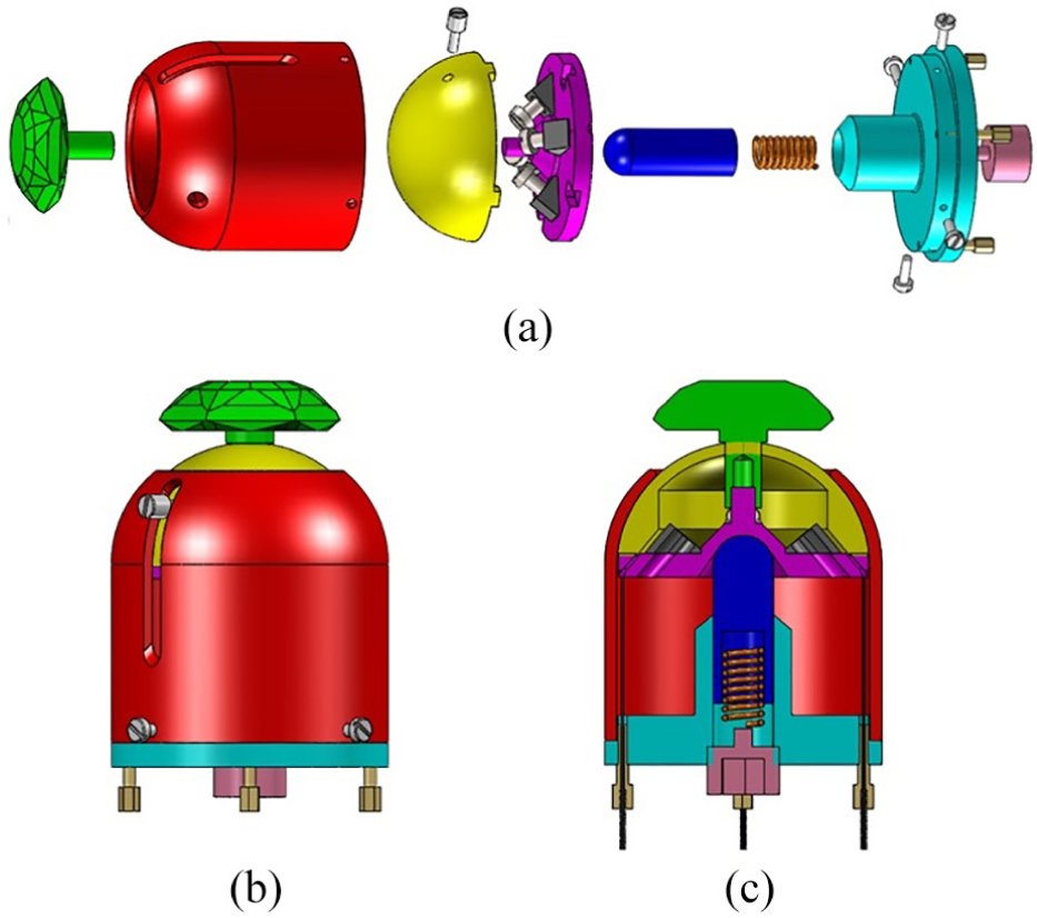
Joystick design: (a) exploded view of joystick components, (b) joystick in assembled configuration, and (c) joystick cross-section including steering cables enclosed by springs.
Manufacture and assembly of all tip, shaft, and handle components led to the final prototype as shown in Figure 6.
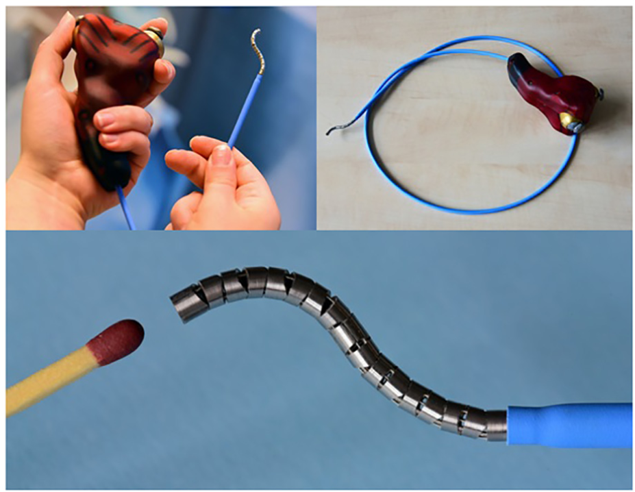
Final catheter prototype.
Proof-of-concept test
Methods
A proof-of-concept test was carried out to study the influence of the shaft position on the shape of the tip. As a first step, we created a set of possible tip shapes that can be achieved with the catheter, resulting in the five tip shapes shown in the top row of Table 1: (1) single bend Segment 1, (2) single bend Segment 2, (3) double bend same plane and same direction, (4) double bend same plane and different direction, and (5) double bend different plane and different direction. These five tip shapes were generated by starting with a straight shaft pathway and a straight tip, after which the joysticks were rotated in the corresponding extreme positions to realize these tip shapes. Next, the tip was straightened again and the catheter shaft was shaped into a sinusoidal shaft pathway (middle row of Table 1) after which the joysticks were again rotated in the extreme positions to generate the five tip shapes. Finally, the same test was carried out with a 360° circular shaft pathway, shown in the bottom row of Table 1.
Visual representation of bending possibilities.
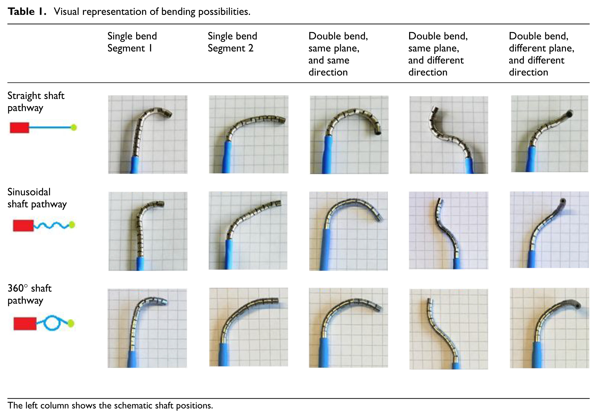
The left column shows the schematic shaft positions.
To create each of the shaft pathways, four cups with a diameter of 6 cm were used. For the straight shaft pathway, two cups were fixated to a bottom surface and two other cups at a relative distance of 1 m. The shaft was running in between the cup pairs and fixed in place to allow the catheter to run along a straight pathway. For the sinusoidal shaft pathway, the four cups were placed in a row with 6 cm distance in between each two cups. The shaft was then guided along the outer diameter of the cups and fixed alternating from the left and right sides of the cups. For the 360° circular shaft pathway, the four cups were grouped together in a square, forming an average overall diameter of 14 cm. The shaft was then curled around the cups to roughly form a 360° bend and fixed to prevent the bend from opening.
For each of the five tip shapes, starting with a straight and neutral tip position, the joystick was first rotated in the extreme position, held there for 5 s, rotated back to its neutral position, held there for 5 s, and then rotated in the same extreme position again and held there for 5 s after which the corresponding photo in Table 1 was made against a background with a 5-mm grid. The tip was not touched during any of these moves and fully controlled by the joysticks alone. For each of the tip shapes and shaft pathways, this motion sequence was repeated 10 times in total leading to 5 × 3 × 10 = 150 photos, of which 15 are shown in Table 1. Subsequently, for each of the 150 photos, a close-up was printed on A3 paper and used to measure the bending angle(s) using a triangle ruler. Mean bending angles and standard deviations were calculated for each of the tip-shaft combinations. In addition, the loss of function was calculated for changing shaft pathway. For this purpose, each of the mean bending angle values of the sinusoidal and 360° shaft pathways was divided by the concerning reference value that was found with a straight shaft pathway. This value was calculated to a percentage for each of the possibilities to calculate the loss of function per combination, and an average loss of function was calculated using all obtained values.
Results
The results show that each of the five tip shapes can be made when the shaft has a straight path, a sinusoidal path, or a circular path, presented in Table 1.
Table 2 shows that with a straight shaft pathway, a single bend for Segment 1 had a mean angle of 102.1° and a single bend for Segment 2 a mean angle of 97.1°. Both of these values are in line with the designed and expected value of 100°. While the loss of function was minimal for Segment 1 during the sinusoidal and 360° shaft pathways, for Segment 2, they were calculated as −26.2% and −10.4%, respectively. A double bend in the same plane and same direction led to a mean bending angle of 174.8° in the straight shaft pathway and a loss of function of −9.9% and −33.8% for the sinusoidal and 360° shaft pathways, respectively. A double bend in the same plane but in other directions led to a two-dimensional S- or Z-shaped curve in which Segment 1 was shaped in a bending angle of approximately 90° in one direction and Segment 2 in a bending angle of approximately 70° in another direction. Having a total mean value of 163.5° for the tip bending angle with straight shaft pathway, the loss of function was calculated as −28.3% and −40.1% for the sinusoidal and 360° shaft pathways, respectively. A double bend in two different planes and two different directions led to a 3D S- or Z-shaped curve in which Segment 1 was shaped into a bending angle of approximately 90° in one direction and plane and Segment 2 in 60° in another direction and plane. With a reference value of 146.3%, the loss of function was −8.7% and 6.3% for the sinusoidal and 360° shaft pathways, respectively. Overall, an average loss of function of 16.6% was observed as a function of shaft pathway changes.
Mean bending angle values with standard deviation.
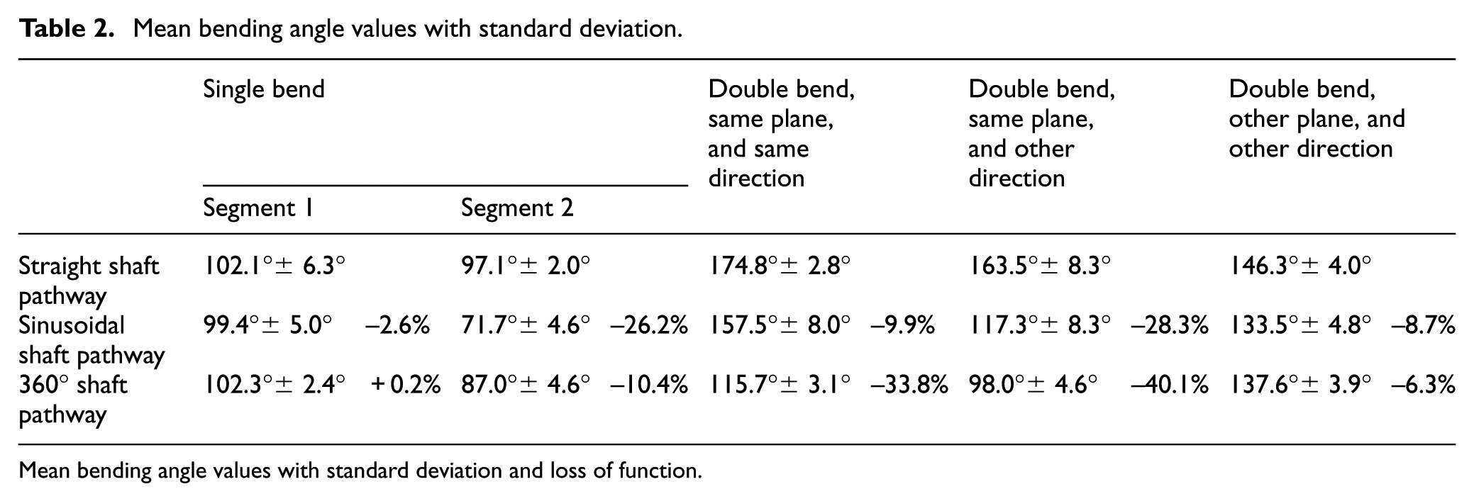
Mean bending angle values with standard deviation and loss of function.
Discussion
Main findings
The importance of the presented work is based on the analysis of underlying mechanical limitations that provide insight in low torsion, shaft shortening, high unpredictable friction, coupled tip-shaft movements, and the need for complex 3D tip motions in the cardiovascular environment. A number of solutions were identified for each of the challenges and used to generate a concept multi-steerable catheter. The concept led to a prototype having two individually steerable 2-DOF deflecting segments at the tip. The multi-steerable catheter was able to steer in multiple directions and planes and was able to create of range of complex curves, including S-shaped curves and full circular motions. Actuation of a single segment was designed to have a bending angle of 100° in each direction and the final prototype was able to reproduce that value. However, a loss of function was observed when both segments were actuated simultaneously, especially when both were bent in the same planes but in other directions. The motion of the tip showed an average loss of function of 16.6% with changing shaft shape. Part of this loss can be explained as a result of human factors: targeting accuracy is predominantly determined by user input and secondary by the mechanical system properties. The exact tip direction and bending angle therefore largely depend on the precision by which the thumb and index fingers manipulate the joysticks. As such, exactly reproducing a bending angle can be a challenge, especially when controlling both joysticks simultaneously. Another reason for the loss could potentially be explained by the internal construction of the shaft. While Bowden cables are used to prevent high friction forces and allow for smooth cable guidance, steering both segments in the same plane may cause the cables to experience a low form of friction. Even though the loss of function was an unwanted effect, the tip remained effectively steerable under extreme shaft conditions. In addition, there was a high variability of tip directions and a relatively simple and reliable repetition of bending angles with a nearly direct response speed. As such, the catheter allowed trial-and-error steering when the 3D tip position was visible to the eye. This is in line with how the catheter is envisioned to be used during clinical procedures in which clinicians will conform the instrument to their own skills and the requirements of the procedure.
Cardiac applicability and future directions
While the dimensions and functions of the catheter were chosen specifically for cardiovascular interventions, a number of characteristics require further optimization for use in the heart. To prevent possible perforation of the cardiac wall while maintaining pushability at the same time, the catheter’s stiffness properties must be optimized for use in the cardiovascular environment. Another stiffness factor is related to overcoming vascular friction while pushing the catheter forward in the vascular system. The material choice must therefore be optimized for use in the heart, with solutions possibly lying in the use of a sealing for the tip and a braided reinforced structure for the shaft to ensure optimal shaft properties. A tip sealing is also recommended to prevent blood from entering the internal construction and to make sure no particles from the inner construction come in contact with blood. It must be noted however that the tip components have been designed such that they move along each other in rolling contact instead of sliding contact. As such, any wear would be negligible and no material will be lost. The use of a thin-walled protective sheet or sealing would be recommended regardless. In addition, the loss of function may be improved, especially when the shaft is following a heavily bent pathway. To provide the operator a form of positional feedback during a procedure with the catheter, bands of radiopaque material could be added to a number of tip components to allow visibility of both tip segments under fluoroscopy. Following the improvements, the multi-steerable catheter is intended for use in the cardiac environment. Future follow-up experiments are planned to test the catheter in a physiologically relevant model of the cardiovascular system using a transparent 3D model based on patient computed tomography (CT) data. In addition, an in vitro procedure in a beating porcine heart is planned with a clinician to determine the catheter’s functionality in a realistic and dynamic environment and in the hands of an expert user. Based on the outcomes of these experiments, the prototype can be further improved towards an animal trial, taking into account the dynamic cardiovascular environment and sensitive anatomy.
Conclusion
A detailed overview was provided of underlying mechanical limitations in steerable catheters and resulted in the design and development of a multi-steerable catheter having four DOFs. Future directions are found in optimizing the used materials for use in the cardiac environment and evaluation of the catheter in cardiac models and a beating heart setting. Our presented technology offers a range of possibilities for future cardiac procedures. The ability to steer inside the heart and allow a variety of complex shape tip curves may potentially change conventional approaches in interventional cardiology and cardiac surgery towards more patient-specific and less invasive procedures.
Footnotes
Acknowledgements
The authors would like to thank the Erasmus Medical Centre in Rotterdam and more specifically their departments of interventional cardiology and electrophysiology for providing them the chance to have multiple meetings with clinical experts and specialists. In addition, the DEMO workshop at Delft University of Technology has had an important role in the manufacturing of the prototype.
Declaration of conflicting interests
The author(s) declared no potential conflicts of interest with respect to the research, authorship, and/or publication of this article.
Funding
The author(s) disclosed receipt of the following financial support for the research, authorship, and/or publication of this article: This work is part of the research project MULTI, design of a multi-steerable catheter for complex cardiac interventions. This project is part of the research programme P11-13 iMIT with project number 12704, which is (partly) financed by the Netherlands Organization for Scientific Research (NWO).