
Abstract
Traditional trajectory optimization methods for the parafoil system set fixed-point landing as the objective. However, in recent payload fairing recovery missions, the recovery system comprising two parafoils is collaboratively recovered by a mobile vehicle, posing new challenges to the current trajectory optimization technique. In order to recover two parafoil systems autonomously with an unmanned surface vessel, this paper presents a trajectory optimization framework composed of three following component processes consecutively. Firstly, a feasibility judgment algorithm based on reachable boundary estimation is designed to determine the possibility of recovering two parafoil systems. Secondly, the decoupled-then-simultaneous strategy is proposed to enhance the convergence of solving the collaborative recovery problem. Thirdly, the finite-element collocation approach is utilized to convert the formulated trajectory optimization problems into nonlinear programming (NLP) problems, which are solved by a highly efficient NLP solver. Simulation results show that the proposed trajectory optimization framework can efficiently generate the optimal trajectory for recovering two parafoil systems with a vessel.
Introduction
Due to the advantages of low cost, high load capacity, and maneuverability, parafoil systems are widely used in space payload recovery, 1 spacecraft landing, 2 and supply delivery. 3 Recently, utilizing the mobile system to recover the parafoil system has become a growing trend. 4 The aerospace company SpaceX has achieved a breakthrough in recovering the payload fairings (PLFs) of the Falcon 9 rocket by catching the parafoil system with a vessel. Meanwhile, another company Rocket Lab has also proposed to recover its first-stage booster with the help of a parafoil system and a helicopter. These projects utilized a mobile vehicle to realize collaborative recovery, which is more flexible than the traditional fixed-point landing approach. 5 The resulting benefit is that the parafoil system can be more light-weighted and better respond to environmental uncertainties since its control burden is relieved by cooperation with the vessel. However, current collaborative recovery practices depend on manual control of the mobile platform to rendezvous with the parafoil system, resulting in extra mission complexity. As a result of underdeveloped technology, SpaceX has postponed its capture attempt and turned to land the parafoil system on the sea. Although the collaborative recovery mission is suspended, it still deserves to be studied in-depth because it is an enabling technology for PLF recovery and provides an alternative method for landing aerospace systems.
In order to achieve collaborative recovery, the mobile system needs to capture the parafoil system before it lands on the sea. Hence, it is necessary to judge the feasibility of recovery, and this relies on estimating the reachable boundary of each vehicle. In the literature on vehicle reentry, the reachable boundary is obtained by calculating a large number of boundary points, which are sampled by grids, 6 segments, 7 or virtual points. 8 Therefore, the problem of determining the reachable boundary is transformed into solving a series of trajectory optimization problems. The advantage of this method is that it takes complicated dynamic and path constraints into account, which enables a characterization of the complex reachable boundary. The downside is that solving considerable optimization problems can be computationally intensive. In studies on aircraft landing, the reachable boundary is estimated by regular closed curves, such as circle9,10 and dual half-ellipse. 11 The advantage of this method is that the reachable boundary is represented by a simple closed curve, which facilitates reachability judgment and reduces the computation burden. Previous literature on parafoil recovery utilize the glide ratio to estimate parafoil system’s reachable boundary. On this basis, the feasibility of reaching the fixed landing point is judged. 12
Trajectory optimization is one of the most important issues in the field of parafoil recovery. It generally falls into two categories: the traditional and the optimal approach. In the traditional approach, the landing trajectory is composed of circles and straight lines, among which the typical ones are the Dubins path 13 and the T path. 14 The optimization algorithm such as chance-constrained rapidly exploring random trees, 15 band-limited guidance method, 16 and heuristic method17,18 is utilized to determine the parameters of landing trajectory. The traditional approach is widely applied in experiments because of its low computing power requirement. However, the dynamic constraints of the system are ignored in this approach. 19 The optimal approach is divided into the indirect method and the direct method. The indirect method derives the first-order necessary conditions according to Pontryagin maximum principle and solves a two-point boundary value problem (TBVP) to obtain the optimal landing trajectory.13,20 The main advantage of the indirect method is that its solution satisfies the first-order optimal condition, and the shortcomings are the small convergence region, cumbersome formulation procedure, and the sensitivity to initial values for TBVP. It is mainly used to handle simplified parafoil models and is not applicable for planning the collaborative recovery trajectory. The direct method is preferred to generate the parafoil homing trajectory because of its ability to approximate dynamics at discrete points and to deal with complex constraints. Gauss pseudospectral method (GPM), which is a class of the direct method, has been used to obtain the numerical solution of parafoil trajectory optimization problems.21,22 The state and control variables are parameterized using global polynomials at collocation nodes derived from a Gaussian quadrature, thus the trajectory optimization problem is transcribed into an NLP problem. For problems with smooth solutions, GPM provides accurate approximations and exponential convergence. 23 However, for problems whose solutions are non-smooth or not well approximated by global polynomials, finite-element collocation approaches24–26 are preferred, where the time interval is partitioned into subintervals and polynomials are used to approximate the state and control profiles over each subinterval. Apart from the work focusing on the fixed-point landing of parafoil system, Hewgley et al. discussed the procedure of recovering the parafoil system with the surface vessel. 27 Sun et al. established the kinematic model of the parafoil system and the vessel, and utilized GPM method to obtain the collaborative recovery trajectory. 5
In this paper, a trajectory optimization framework is proposed for the collaborative recovery of two parafoil systems using an unmanned vessel, with the purpose to reduce the operation expense of PLF recovery and provide an alternative approach for recovering two PLF-parafoil systems. The recovery process is formulated as a trajectory optimization problem that consists of vehicle dynamics, boundary constraints, and path constraints. To determine the possibility of recovering two parafoil systems, reachable boundaries of vehicles are estimated and a feasibility judgment algorithm is designed. The direct method is often sensitive to the initial guess, and a rough initial guess may lead to solution failure of the corresponding NLP problem. 28 Thus, the decoupled-then-simultaneous strategy is designed to improve the convergence of solving process and simultaneously optimize the overall trajectory. For the established trajectory optimization problem, the finite-element collocation approach is selected to transcribe the trajectory optimization problem to NLP problems addressed by the off-shelf solver. The main contributions of this paper lie in that (1) The collaborate recovery between two parafoil systems and an unmanned surface vessel is innovatively proposed; (2) The feasibility judgment of recovering the parafoil system with the unmanned surface vessel is discussed for the first time; and (3) The decoupled subproblems are formulated and solved to provide a high-quality initial trajectory for the collaborative recovery trajectory optimization process, so as to improve the convergence property.
Collaborative recovery problem
In this section, dynamic models for the collaborative fairing recovery process are modeled, the constraints acting on the vehicles are established, and the overall trajectory optimization problem is formulated in the end.
Dynamic models
The motions of the parafoil system and the vessel are described in the ground coordinate O
R
X
R
Y
R
Z
R
, as shown in Figure 1. Its origin O
R
is located at the vessel’s initial position. The O
R
Y
R
axis points to the anti-wind direction, the O
R
X
R
axis points to right hand, and the O
R
Z
R
axis makes up a right-hand coordinate system. We define the body coordinate of each vehicle as O
B
X
B
Y
B
Z
B
. Its origin O
B
locates at the center of the parafoil system. Coordinates of collaborative recovery.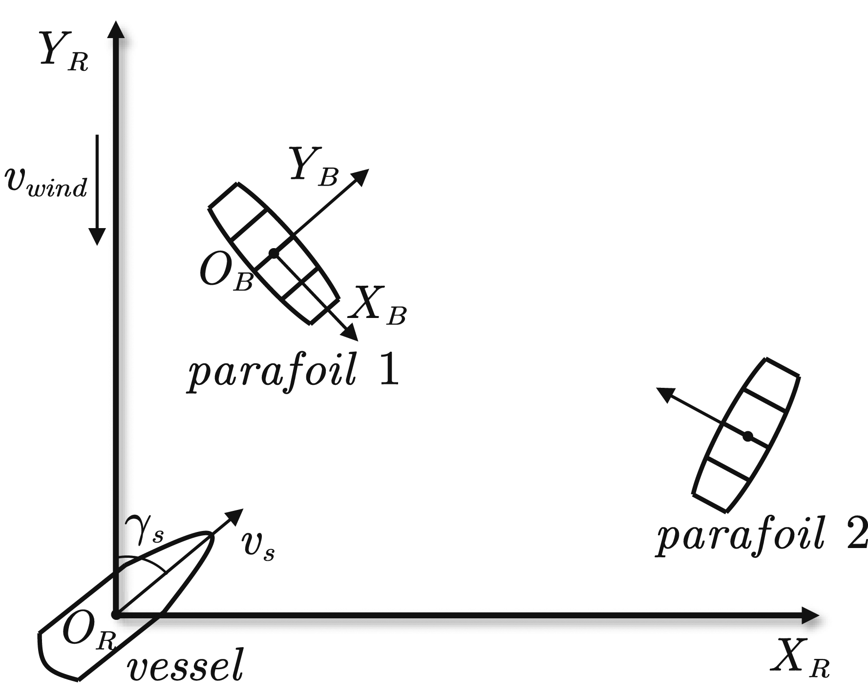
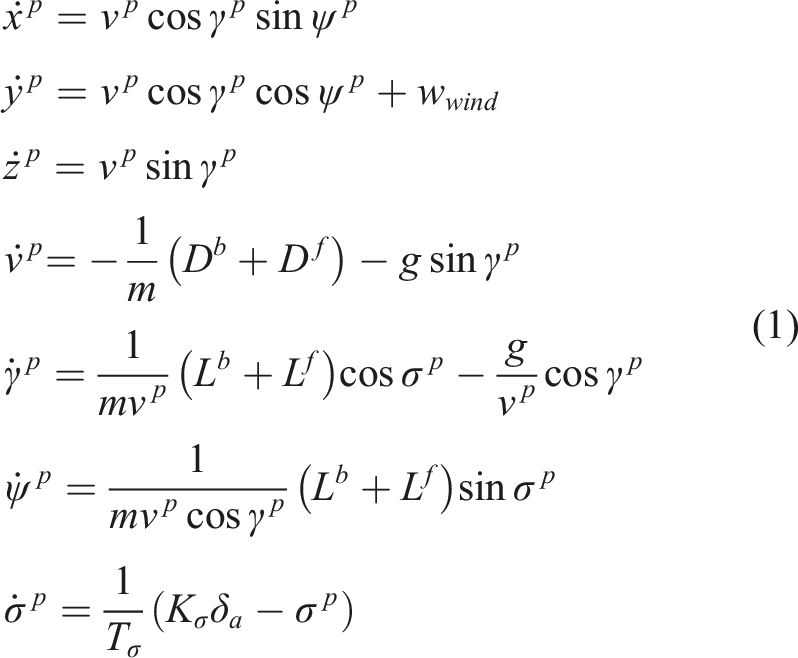
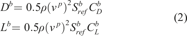
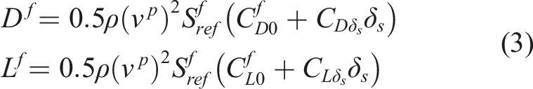
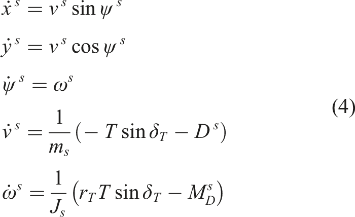
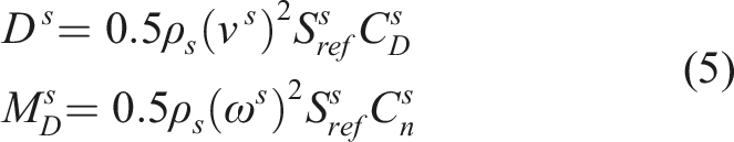
Given that the parafoil system is unpowered and underactuated, it is sufficient to use the three degree-of-freedom (DOF) model to optimize its movement trajectory. The dynamic equations of the parafoil system are as follows12,13:
Unlike the parafoil system, the unmanned vessel is powered by the engine to directly change its speed and angular velocity, making it necessary to incorporate the angular velocity term into the dynamic model. Hence, the dynamics of the vessel are expressed as follows:
Constraints
The state and control variables of the parafoil system are denoted as


The initial constraints are expressed as follows:


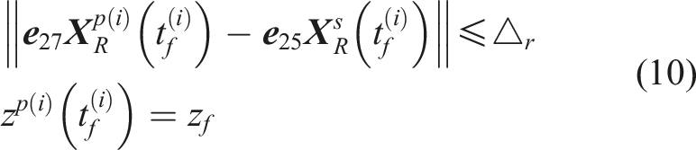
Three terminal constraints are enforced when the vessel rendezvous the parafoil system. First, the distance between two vehicles should meet the specified threshold when the parafoil system reaches the terminal height. This ensures that the parafoil system is accurately captured by the net installed on the unmanned vessel. Second, the heading angles of the two vehicles should be kept close to guarantee that the parafoil approaches from aft of the vessel. Third, the parafoil system should land near upwind to perform a flared landing, thus reducing its ground velocity.


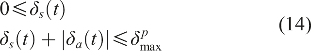
The total flap deflection of the parafoil system is limited, leading to constraints on the symmetric and asymmetric flap deflection angle.
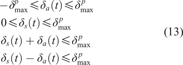
The above constraints can be simplified as:
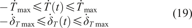
Similarly, the margin and direction of the vessel’s thrust are constrained due to power and mechanical limits.


What’s more, the maximum velocity of the vessel is restricted, and reverse movement is not allowed:

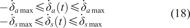
To provide a smooth control profile for trajectory tracking and control, the change rates of controls are constrained as:
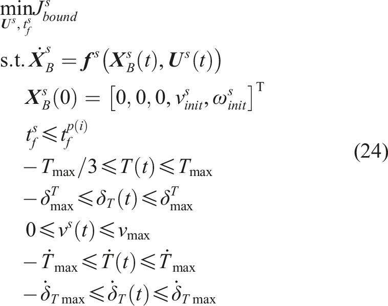
Overall formulation
The main objectives, including the landing precision and landing direction have already been considered in the terminal constraints. Therefore, the control energy is considered in the objective function. Firstly, the flap deflection control of parafoil systems are minimized to reduce the control effort of electrically driven motors, which commands the control line to deflect left and right flaps. Similarly, thrust control of the vessel is minimized to reduce fuel consumption. Thus, the objective function that minimizes the control energy is defined as follows
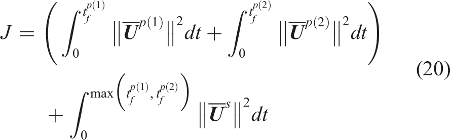
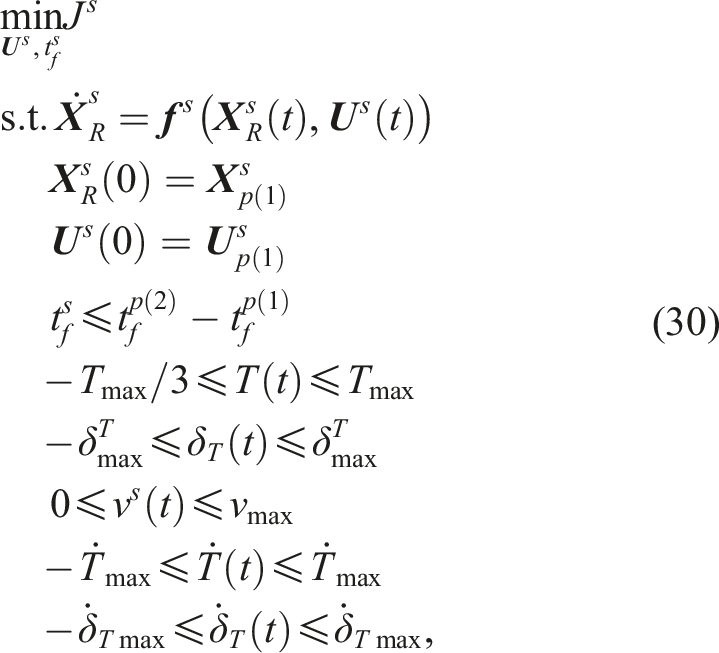
Then, the collaborative recovery trajectory optimization problem is constructed as
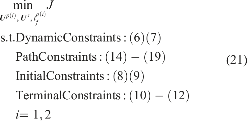
The formulated trajectory optimization problem contains the dynamics and related constraints of two parafoil systems and an unmanned vessel, leading to a larger problem size than the usual pinpoint landing. Besides, the capture moments of two parafoil systems are optimization variables, meaning that it is a complex two-phase free-terminal-time problem. Directly handling Problem P1 may get stuck at an infeasible point or fail to converge. In the following sections, we will design methods to judge the feasibility of collaborative recovery and obtain optimal recovery trajectories.
Recovery feasibility judgment
In this section, the reachable boundaries of the parafoil system and the vessel are estimated. Based on the estimation, a feasibility judgment algorithm is designed to determine the possibility of collaborative recovery and estimate the recovery point.
Reachable boundary estimation
According to Wu and Clothier
11
the reachable boundary of the flight vehicle is closely related to its flight time. Since we estimate the parafoil’s reachable boundary at the start of the recovery mission, its flight time is long enough to perform a turning maneuver. Therefore, it is appropriate to use a circle to estimate the reachable boundary of the parafoil system. As in Figure 2, the estimated circle is determined by three points in the body coordinate. Point Illustration of estimated circle.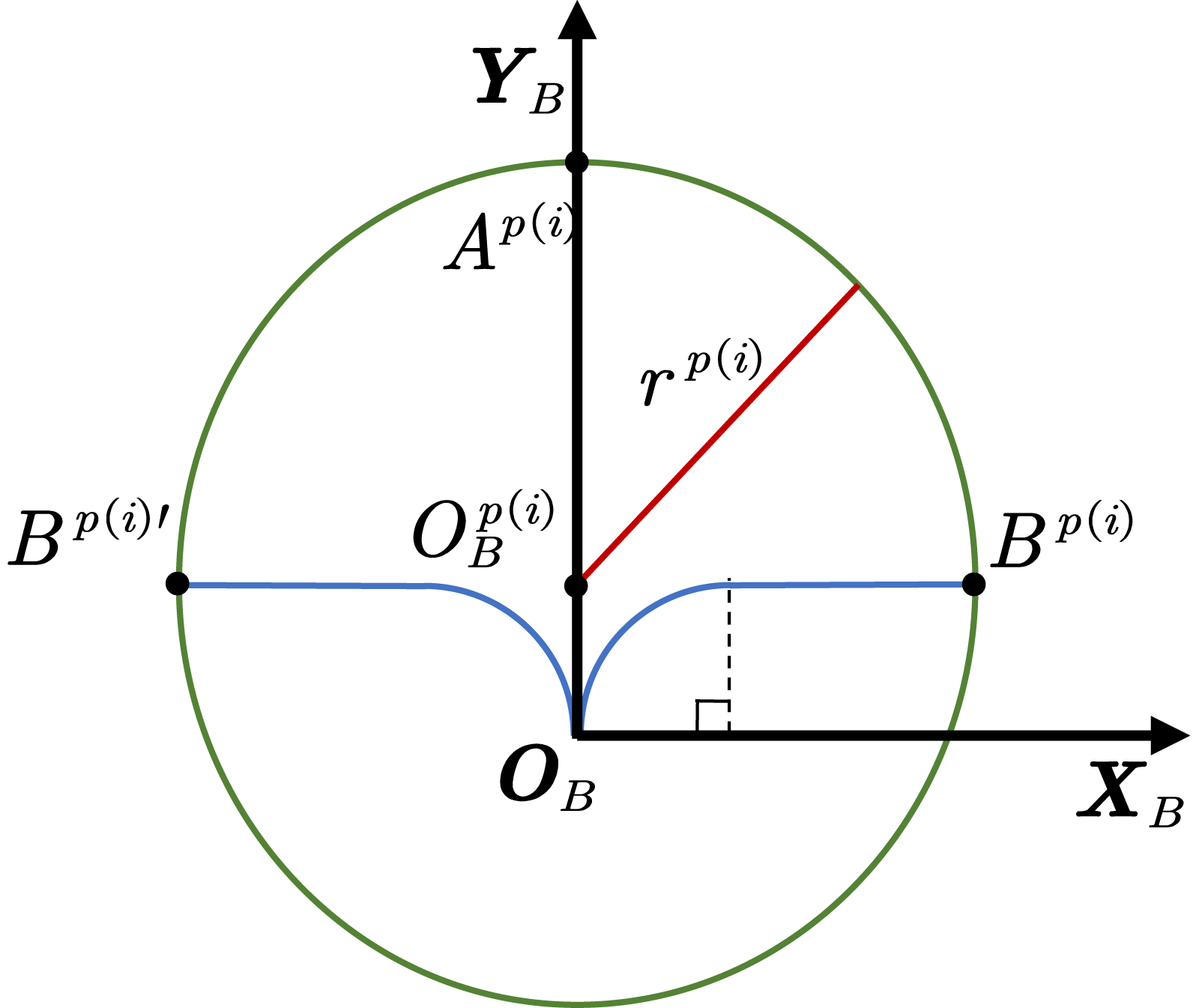
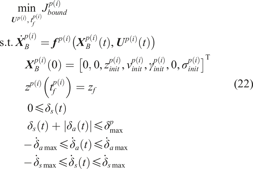
In consideration of the dynamic model and related constraints, we formulate the following trajectory optimization problem to obtain the boundary points, whereas the penalty term replaces the original cost function (20). The problem is referred to as
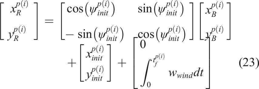
After estimating the reachable boundary of the parafoil system in the body coordinate, the rotation and translation transformations are conducted to acquire the reachable boundary in the ground coordinate.
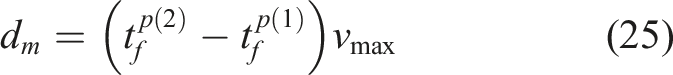
The reachable boundary of the vessel is determined by the parafoil system it aims to catch. To be specific, the flight time
The reachable boundary in the ground coordinate is acquired through rotation and translation transformations similar to (23). The only difference is that the influence of the wind field is ignored when considering the vessel’s reachable boundary.
Feasibility judgment algorithm
Due to the unpowered nature of parafoil system, it has limited control to its vertical velocity. Hence, the flight time of each parafoil system is determined by the initial altitude. In the collaborative recovery mission, the initial altitudes of parafoil systems are set to different values, thus enabling the vessel to perform sequential recovery. To facilitate discussion, we denote the parafoil system with lower altitude as Parafoil 1 and the other parafoil as Parafoil 2. Based on the analysis above, the reachable boundaries of Parafoil 1 and Parafoil 2 are estimated as circle
If circle Three cases of C. (a) C1, (b) C2, and (c) C3.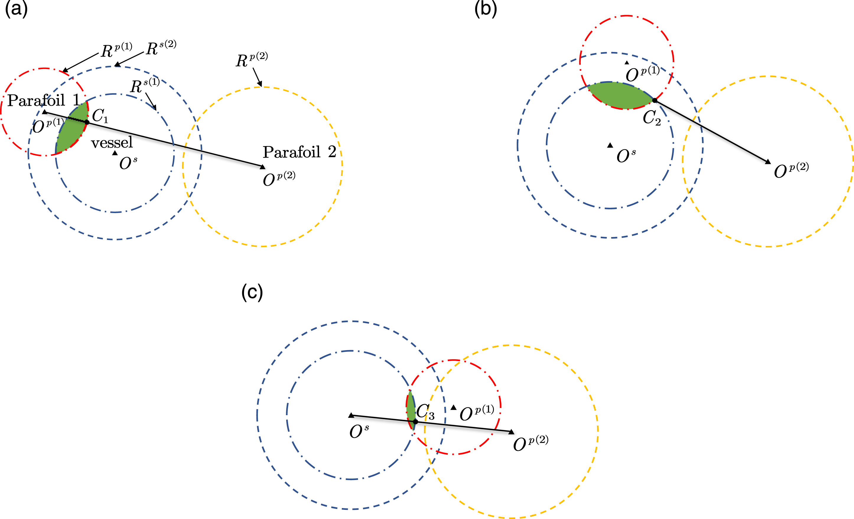
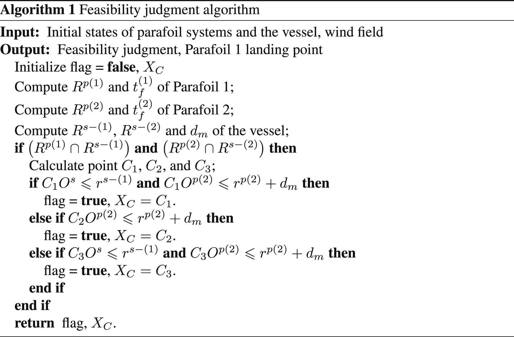
Based on the above discussion, the feasibility judgment algorithm is demonstrated in Algorithm 1. It effectively excludes infeasible conditions and provides a reference for the mission design. Note that this judgment algorithm provides an optimistic estimate and the ultimate recovery feasibility remains to be determined in the trajectory optimization procedure. One reason is that the estimated boundary is larger than the actual reachable area, as is shown in Section 5. Another reason is that the boundary and path constraints are not fully considered in the feasibility judgment. Hence, the feasibility judgment algorithm is utilized to make a preliminary judgment and provide X C as the estimated landing point of Parafoil 1.
Trajectory optimization framework
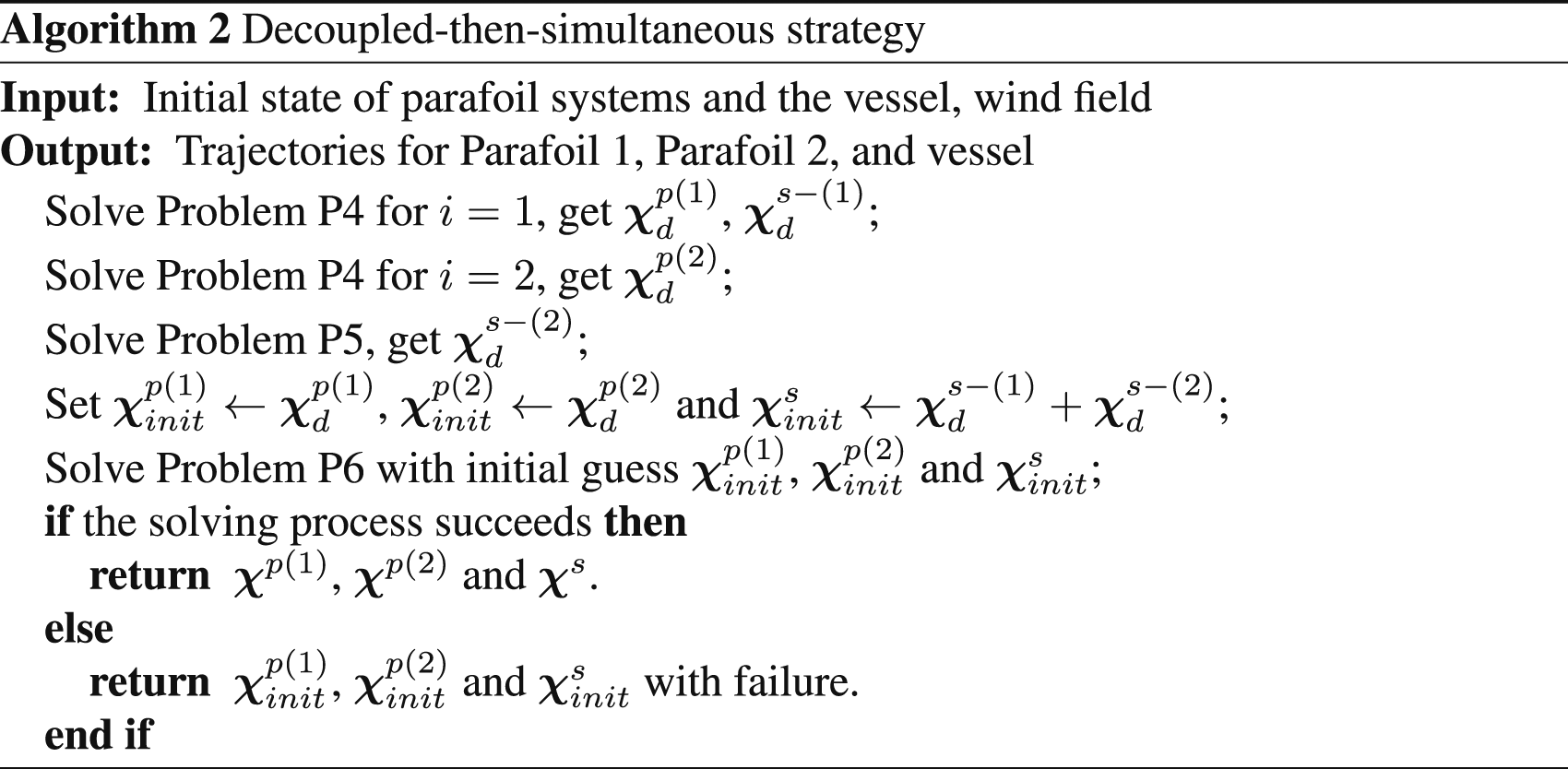
In this section, the decoupled-then-simultaneous strategy is designed to handle the collaborative recovery trajectory optimization problem. First, the origin problem is decoupled into three simple subproblems, through which the reference trajectory is obtained. Then, the simultaneous problem is tackled to obtain the overall trajectory. After that, the finite-element collocation approach discretizes trajectory optimization problems into NLP problems solved by an efficient solver. Finally, the overall trajectory optimization framework is presented.
Decoupled-then-simultaneous strategy
Since the collaborative recovery problem formulated in Section 2 is a complex multi-vehicle free-terminal-time problem, the direct method may get stuck at an infeasible point or fail to converge. It is necessary to provide a high-quality initial guess, which satisfies dynamic constraints and reduces path and terminal constraints violation, so as to start the iteration and improve the solution convergence. Hence, the decoupled stage is introduced to provide feasible trajectories as an initial guess for the solving process.
To acquire the trajectory of two parafoil systems, the single parafoil recovery problem is established, where Parafoil 1 and Parafoil 2 are considered separately. The terminal position constraint in (10) is reformulated as a cost term in the cost function, which reduces the solution difficulty. Another penalty term that minimizes the distance from the parafoil landing point to point X
C
is added, making the landing positions of two parafoil systems as close as possible. Therefore, the cost function
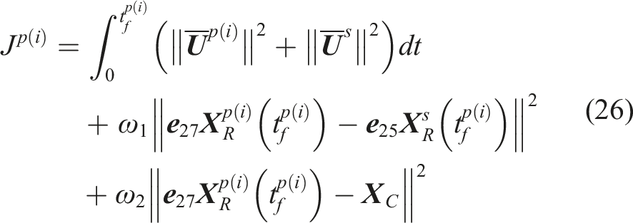
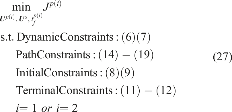
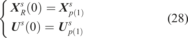
Solving the Problem P4 for i = 1 and i = 2 provides the trajectory of Parafoil 1 and Parafoil 2, along with the trajectory of vessel to recover Parafoil 1. Hence, the remaining work is to obtain the trajectory for the vessel to travel from the landing point of Parafoil 1 to that of Parafoil 2. The corresponding boundary constraints of the vessel are:
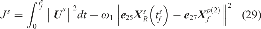
The advantage of the decoupled stage is that it decouples the complex original problem into three trivial subproblems. Besides, the terminal position constraints are imposed as penalty terms in the cost function, which further reduces the solution difficulty. However, the decoupled framework and penalized terminal distance condition may lead to suboptimal trajectories, and the maneuverability of vessel is not fully exploited. Therefore, it is necessary to solve the collaborative recovery problem in a unified framework that comprehensively considers the control margins of all vehicles while meeting the strict capture constraints. To overcome the computation difficulty, outputs of the decoupled stage are taken as the initial guess here. The time-domain of the simultaneous problem is divided into two phases:
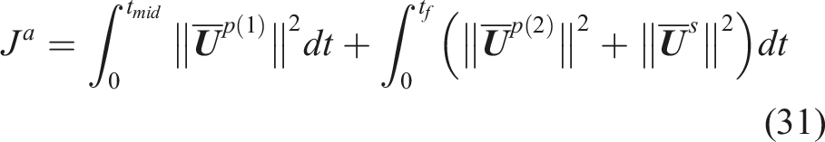
To ensure the continuity of state variables, linking constraints at the intermediate point are imposed.
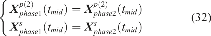
Therefore, the complete simultaneous trajectory optimization problem (
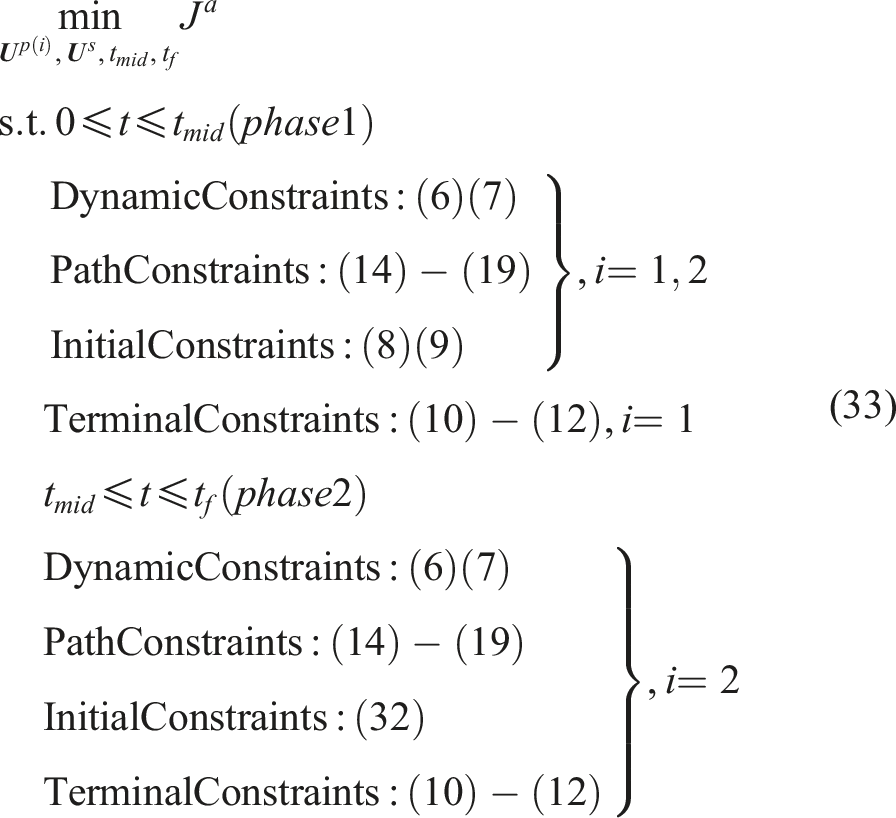
As discussed above, the decoupled-then-simultaneous strategy is generally divided into two stages. In the first stage, two parafoil recovery problems (Problem P4) are solved separately. After that, we get
Finite-element collocation approach
As a class of the direct method, the finite-element collocation approach fully discretizes the state and control variable, converting the trajectory optimization problems into a large-scale NLP problem solved by the numerical solver. Without loss of generality, the following trajectory optimization problem is considered.24,25
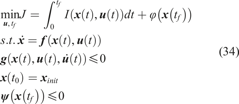
The integration part in the cost function is converted to differential and boundary constraints, and the newly defined differential variable
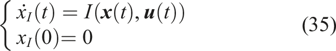
The objective function is transformed into:

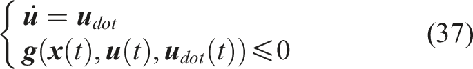
The inequality constraints on the derivative of control variables are transformed into differential and inequality constraints with an added variable
First, the free-terminal-time problem is transformed into a fixed-terminal-time problem by introducing a new variable

The normalized time horizon σ is evenly divided into N finite elements, which satisfies:

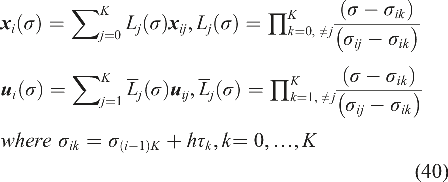
Then K + 1 interpolation points are selected in each finite element i. The state and control variables are approximated by Lagrange polynomial as follows:
The boundary constraints are fixed at the first and last finite-elements:


The continuity of the state variables at the finite-element boundaries is enforced:

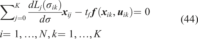
Utilizing (40), the collocation equations at the interpolation points are derived as:
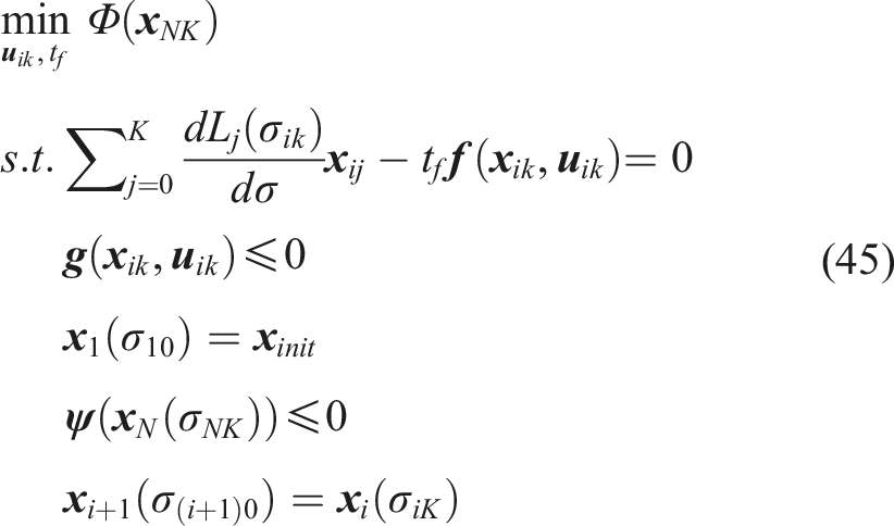
Eventually, the trajectory optimization problem is discretized into the following NLP formulation solved by the highly efficient NLP solver. The solution is returned as the maneuvers of parafoil systems and the vessel.
Overall framework
To better illustrate how the trajectory optimization framework works, the whole procedure discussed above is presented in Figure 4 and concluded as follows: Trajectory optimization framework for collaborative recovery.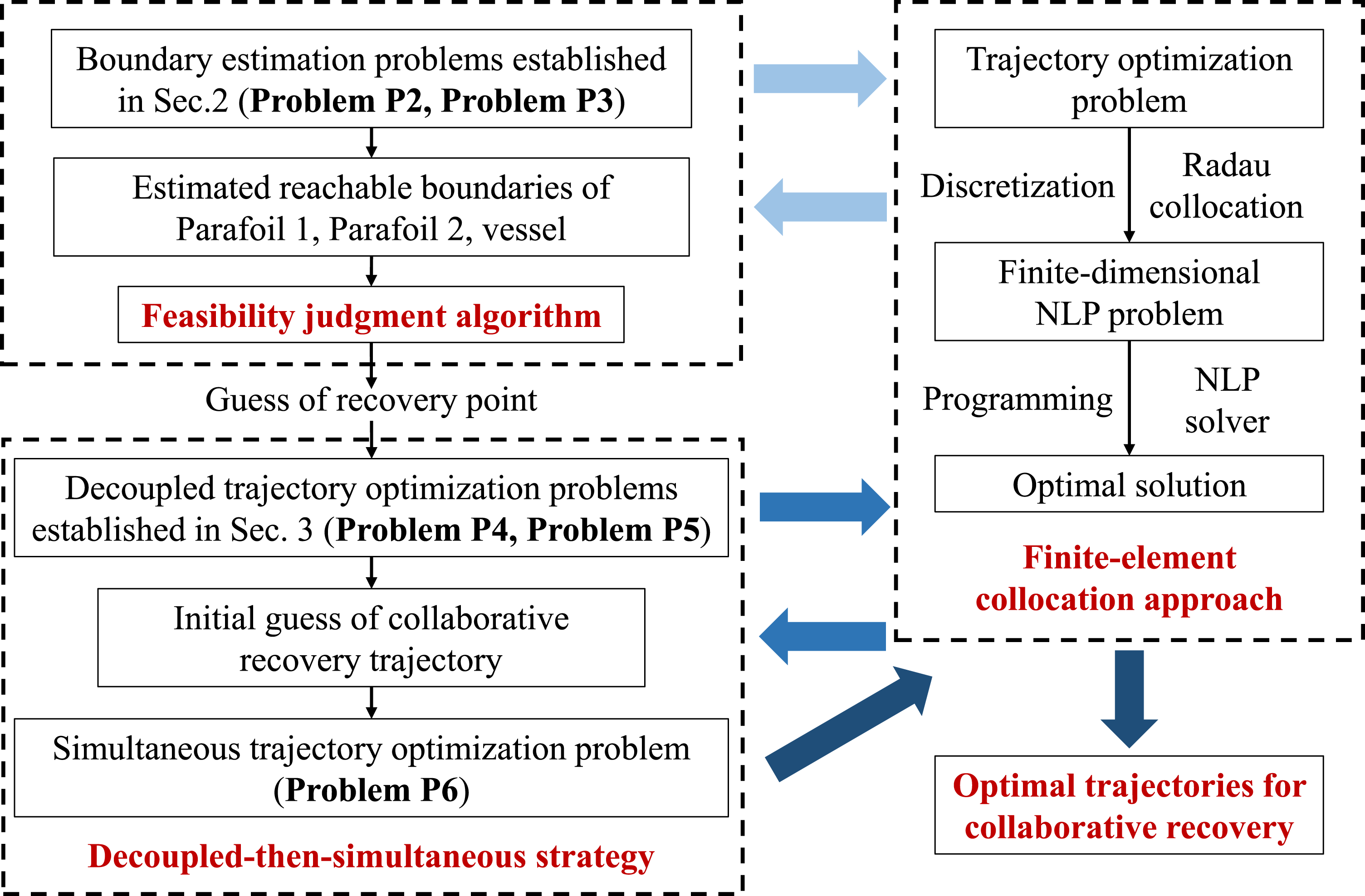
The boundary estimation problems (Problem P2 and Problem P3) are solved by finite-element collocation approach to estimate the reachable boundaries of Parafoil 1, Parafoil 2, and the vessel;
The feasibility of collaboratively recovering two parafoil systems with the vessel is judged via Algorithm 1;
Once the collaborative recovery is judged feasible, the guess of recovery point is provided to formulate decoupled trajectory optimization problems (Problem P4 and Problem P5);
The decoupled trajectory optimization problems obtained in Step 3 are solved to provide the initial guess of collaborative recovery trajectory;
The simultaneous trajectory optimization problem (Problem P6) is solved by the finite-element collocation approach based on the initial guess in Step 3;
The optimal trajectories for collaborative recovery are output.
Results and discussions
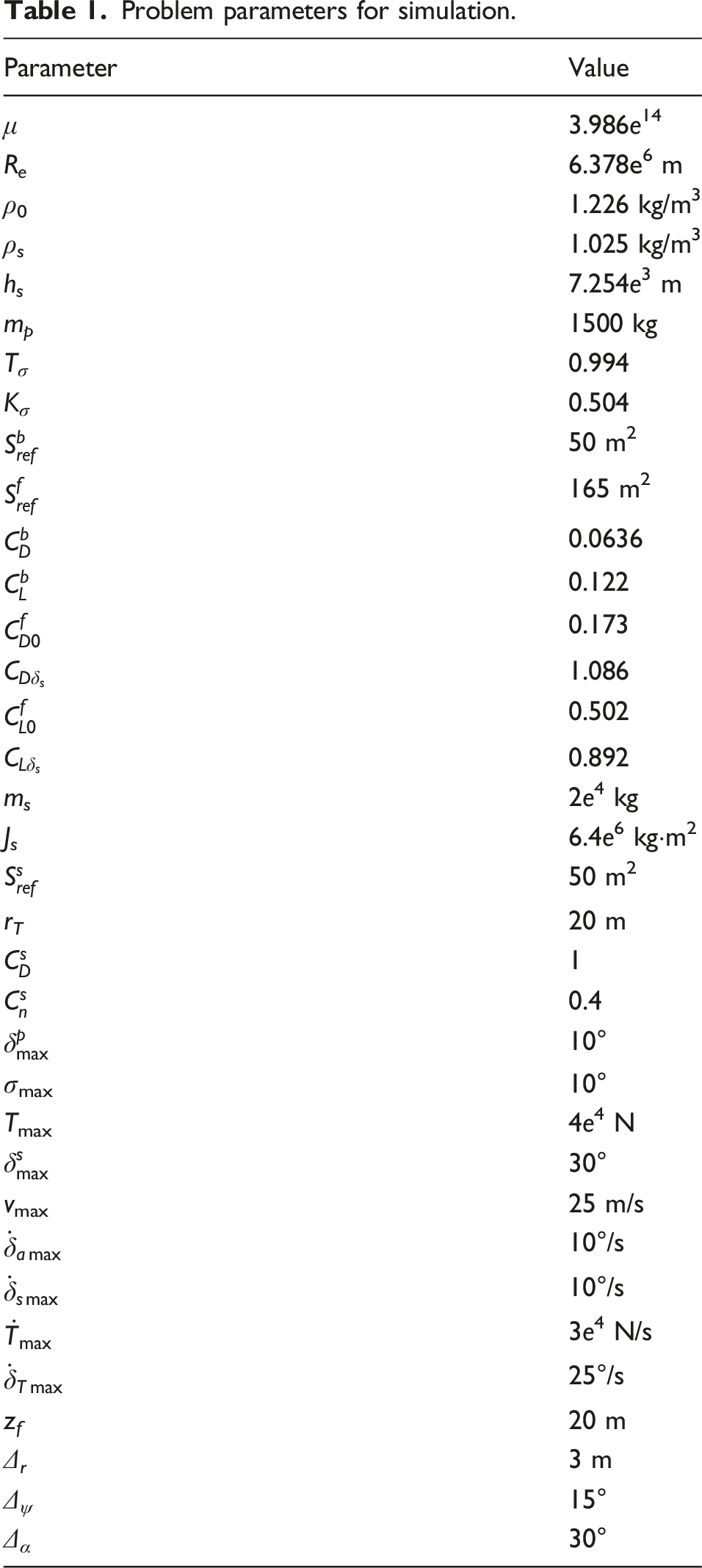
Problem parameters for simulation.
Reachable boundary estimation results
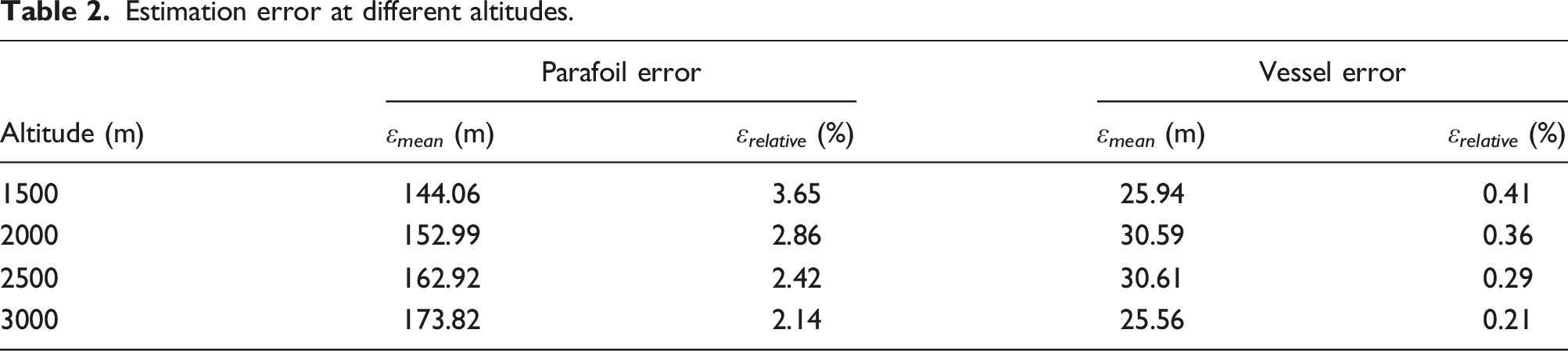
In this section, the effectiveness of reachable boundary estimation is validated, and the approximation error is analyzed. As is depicted in Figure 5, reachable boundaries of the parafoil system and the vessel are approximated by circles, each of which is determined by three boundary points computed in Section 3. A series of optimization problems similar to Problem P2 and Problem P3 are solved to sample the reachable boundary. Figure 5 shows that the obtained boundary points are contained in the estimated circle. The turning radius in Figure 5(b) is smaller than that in Figure 5(a) because the vessel has more turning maneuverability than the parafoil system. Comparison of estimated circle and sampled boundary points (altitude 3000 m). (a) Parafoil and (b) vessel.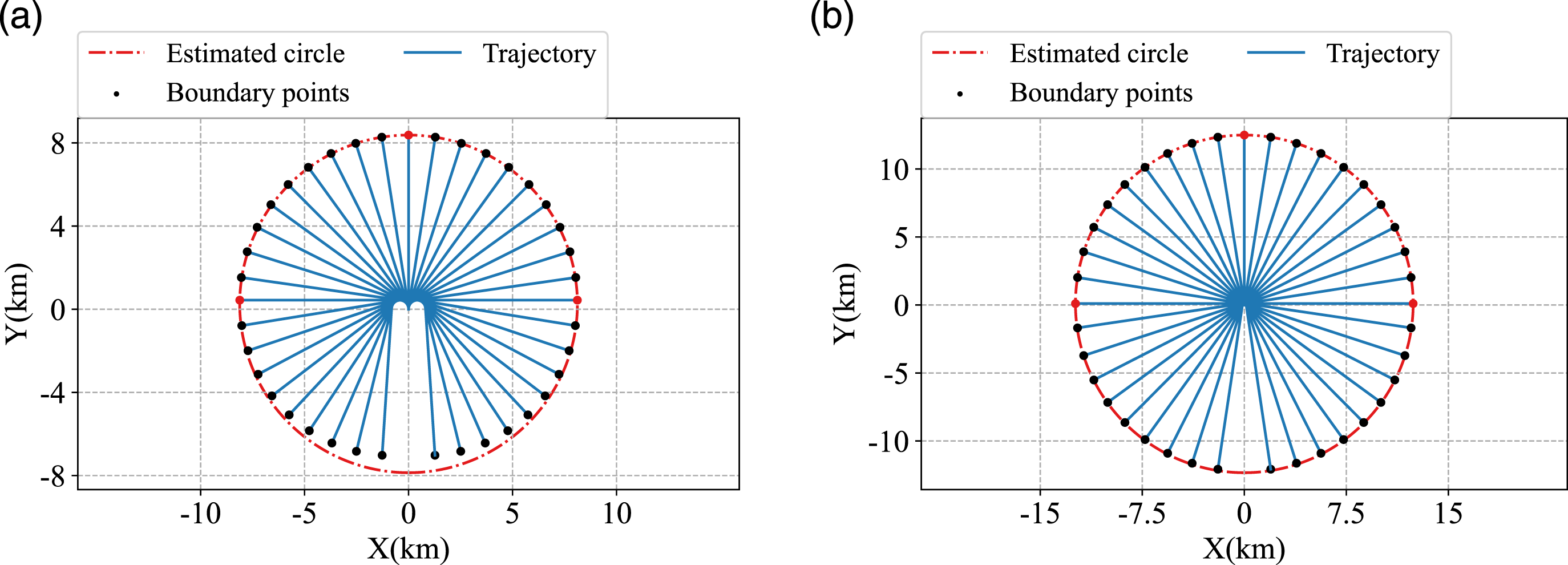
Estimation error at different altitudes.
Trajectory optimization results
Parameters of four collaborative recovery cases.
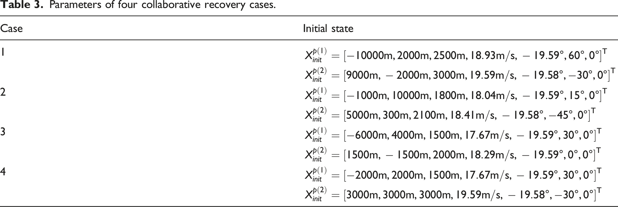
The reachable boundary estimations of four cases are depicted in Figure 6. The circles represent the estimated reachable boundary for each vehicle. The start and end points are marked by the solid square and the solid circle, and the initial heading angle is represented by the arrow. According to the feasibility judgment algorithm, the vessel cannot recover both parafoil systems in Case 1 due to the significant initial distance. As for the other three cases, the feasibility judgment algorithm determines that it is possible to conduct collaborative recovery and provides the guess of landing point. Then, the trajectory optimization is performed, and the obtained flight trajectories are presented in Figure 6. Specifically, in Case 2, the conditions ( Collaborative recovery results of four cases. (a) Case 1, (b) case 2, (c) case 3, and (d) case 4.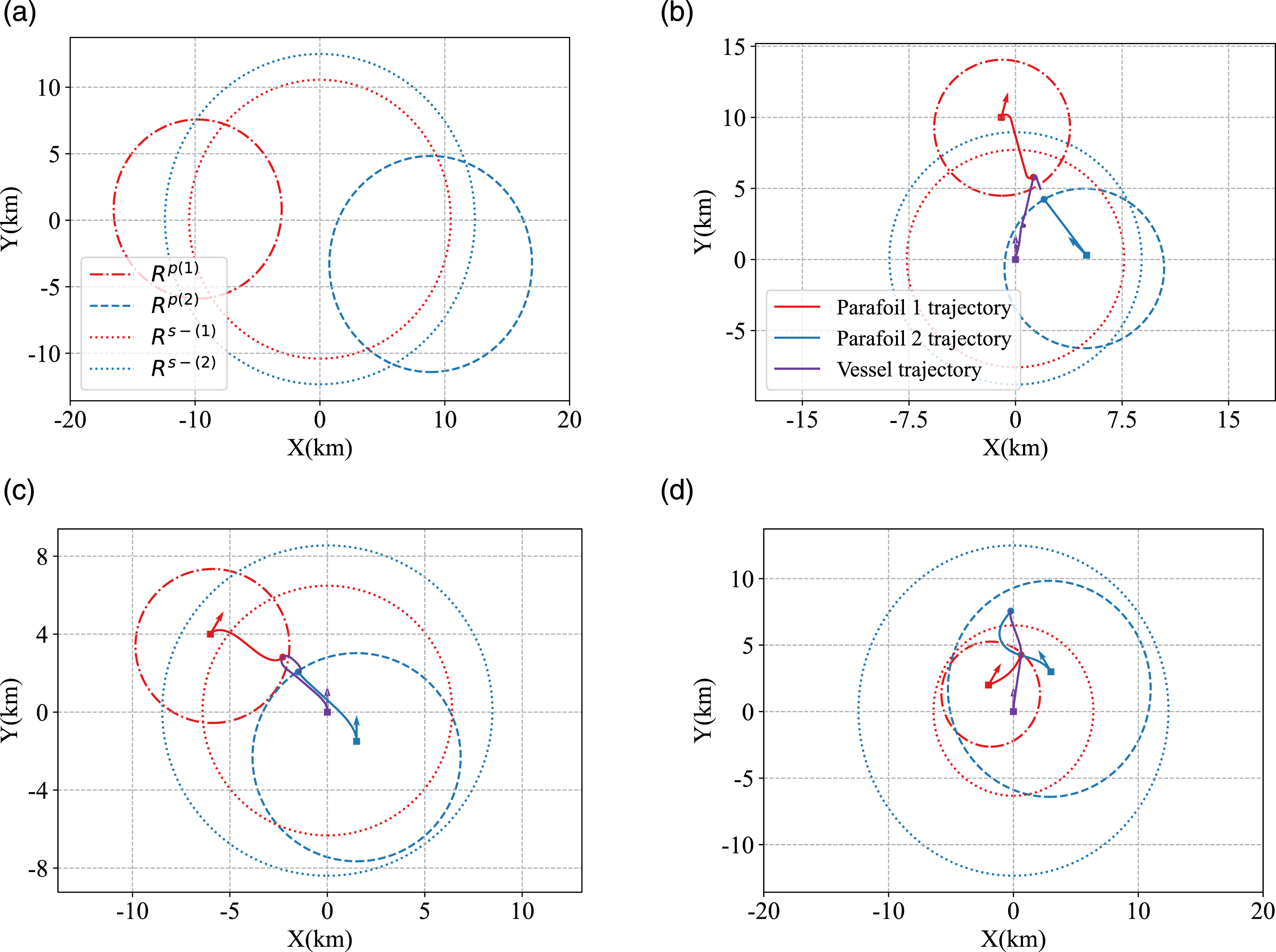
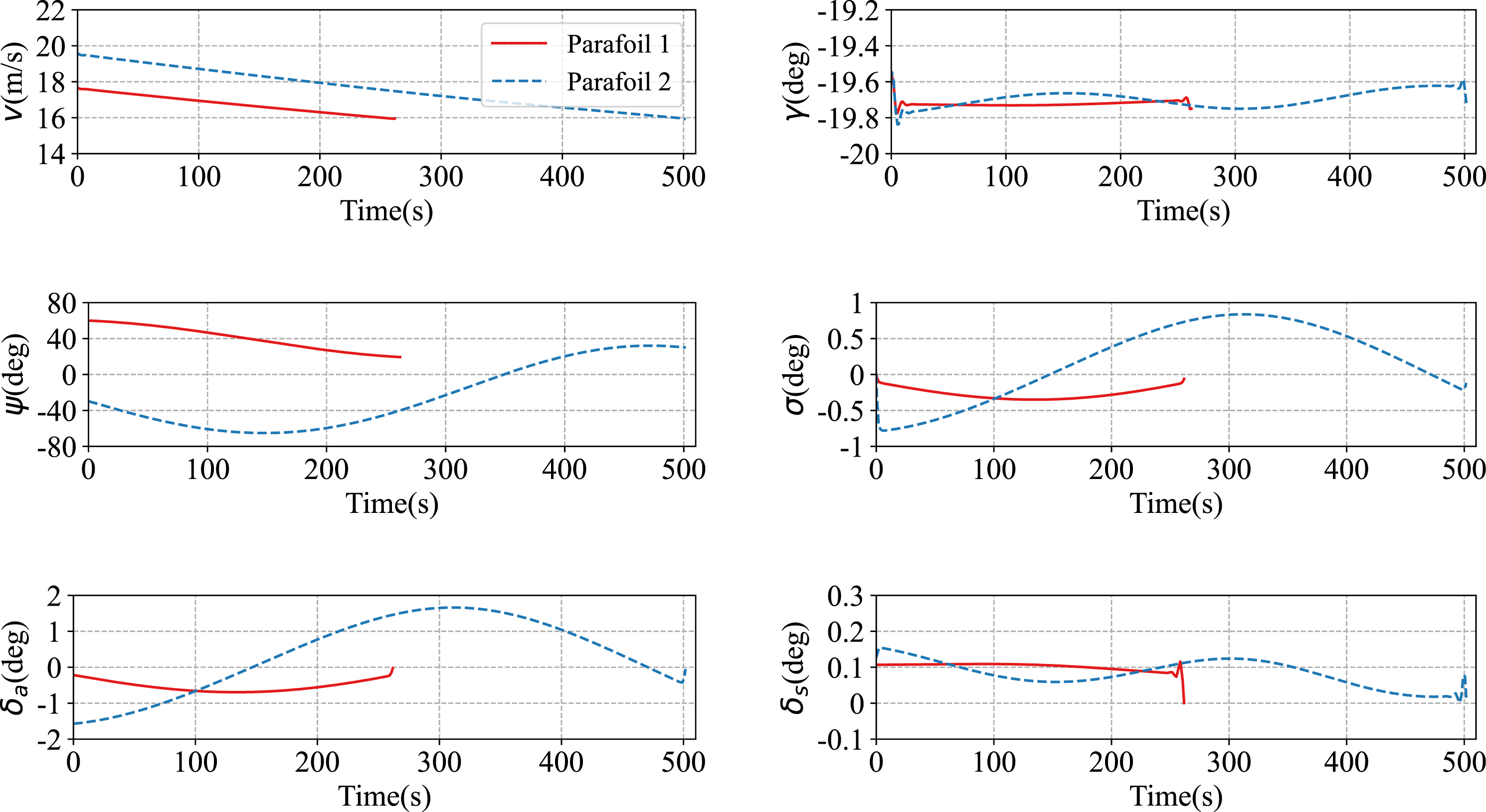
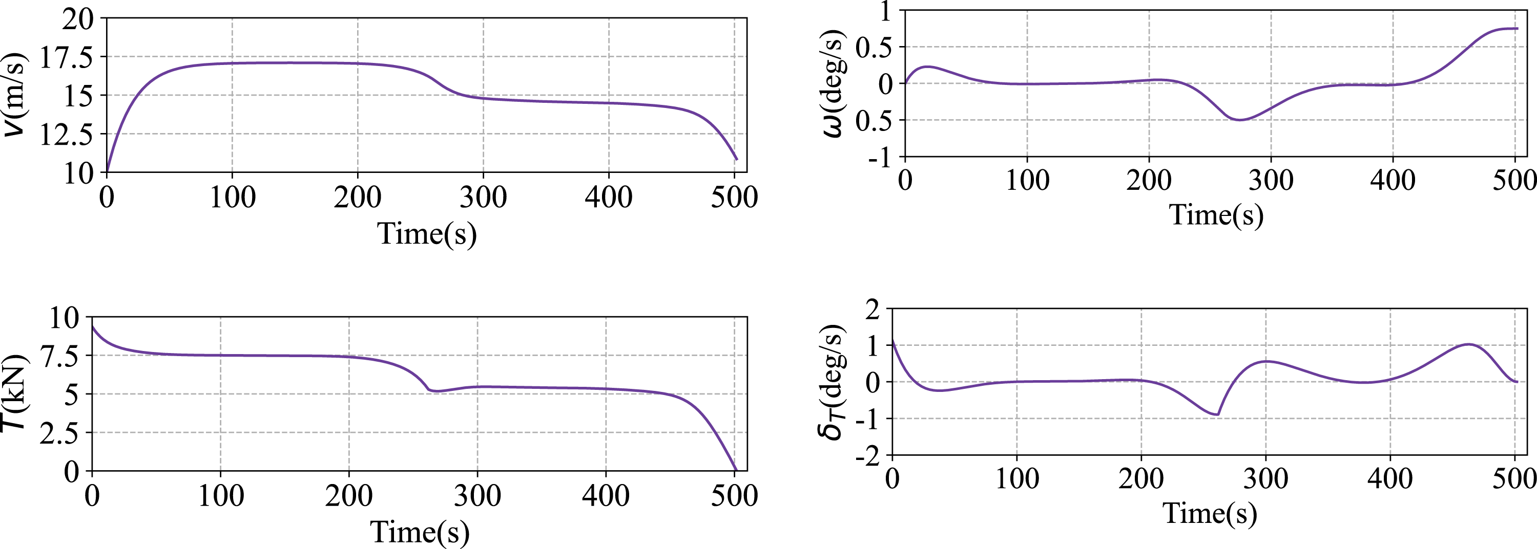
Figures 7–9 depict the results of Case 4, where Parafoil 1 and Parafoil 2 are captured at 261.85 s and 500.07 s, respectively. The objective of recovering two parafoil systems is achieved successfully. Parafoil 1 makes a left turn maneuver and Parafoil 2 makes a right turn to approach from aft of the vessel and performs an upwind landing. The vessel accelerates to catch Parafoil 1 and then maneuvers an S-turn to recover Parafoil 2. Compared with Case 3, the initial distance between two parafoil systems decreases from 9.3 km to 5.1 km, and the capture time interval increases from 83.58 s to 240.26 s. Because of these favorable conditions, the vehicles accomplish the collaborative recovery with a smaller movement. This indicates that it is necessary to keep the two parafoil systems close in the horizontal plane and maximize the time interval between captures in the future recovery mission. Trajectory results of case 4. (a) 3-D and (b) X-Y plane. State and control profiles of parafoil (case 4). State and control profiles of vessel (case 4).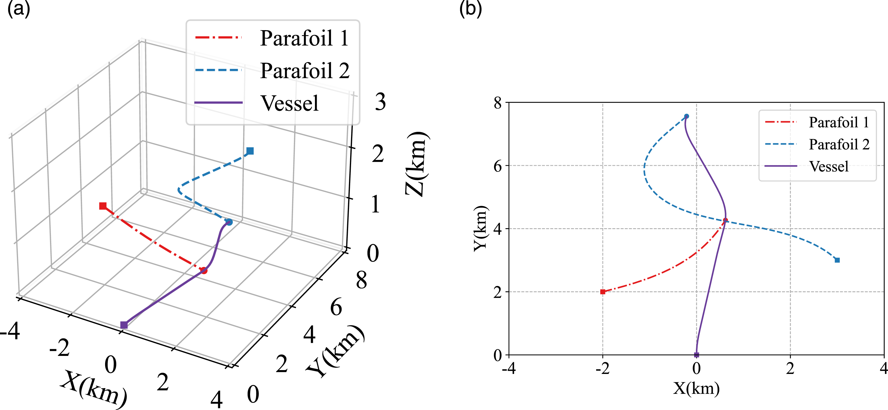
Monte-Carlo simulation
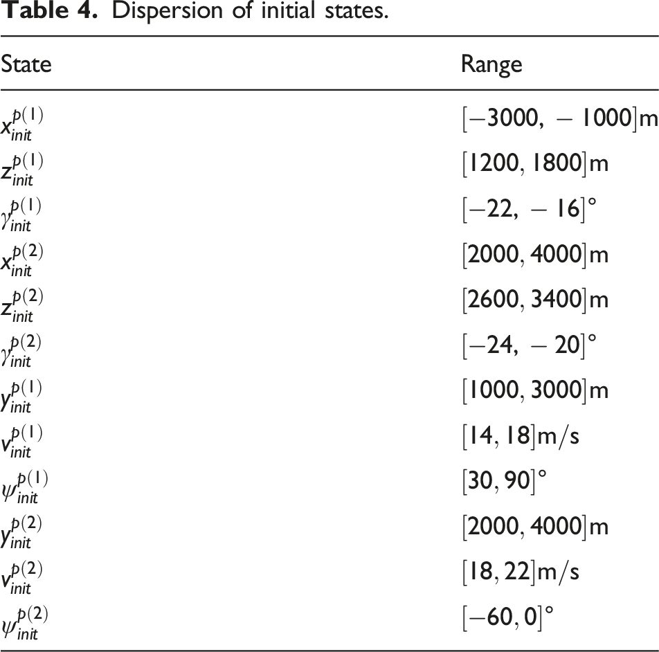
Dispersion of initial states.
Algorithm comparison results.
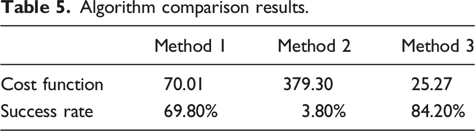
From Table 5, Method 1 successfully solved 69.8% of trials, while Method 2 only tackles 3.8% and obtains a larger cost function than Method 1. This means that Method 2 either fails to converge or gets stuck in the local optimum. In contrast, Method 3 excludes 73 infeasible trials via the feasibility judgment algorithm and successfully solves 421 trials of the remaining 427 trials. Consequently, Method 3 achieves a success rate of 84.2% (421/500) and obtains the smallest cost function. The developed algorithm (Method 3), Method 1, and Method 2 all witnessed failure cases. For Method 3, this is because infeasible cases are recognized by the proposed framework; For Method 1 and Method 2, this is because the IPOPT solver is stuck at local infeasible or suboptimal points despite the fact that some of the cases are feasible. Compared with Method 1 and Method 2, the proposed trajectory optimization framework has a higher success rate in solving the collaborative recovery problem. It validates the improved robustness of the proposed framework in improving solution convergence and solution optimality under different constant wind conditions and initial state conditions.
The trajectory optimization results of Method 3 are presented in Figure 10. For the purpose of illustration, only 100 successful trials are plotted. In most of the trials, the vehicles perform a similar maneuver to realize collaborative recovery. Only in a small number of trials, the vessel or parafoil system makes a huge turn to realize landing in the same direction. The trajectory results demonstrate that the optimization framework proposed in this paper is robust to the dispersion of initial states. Trajectory results of Monte-Carlo simulation.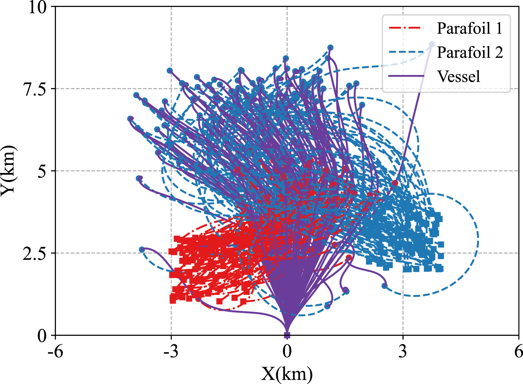
Conclusion
This paper proposes a trajectory optimization framework for collaboratively recovering two parafoil systems using an unmanned vessel. A trajectory optimization problem that characterizes vehicle dynamics and related constraints is established. The reachable boundaries of vehicles are estimated as circles, based on which the feasibility algorithm is designed. For solving the collaborative recovery problem, the decoupled-then-simultaneous strategy is designed, where the decoupled stage generates an initial trajectory guess and the simultaneous stage obtains the optimal trajectory. All problems are discretized by the finite-element collocation method and solved as an NLP problem. Simulation results show that estimating the reachable boundary as a circle is appropriate. The proposed trajectory optimization framework effectively solves the collaborative recovery problem and generates the trajectory. Through Monte-Carlo simulation, the robustness of the proposed framework to initial state deviation is validated. Comparing with the direct application of the finite-element collocation method, the proposed framework has better convergence property and solution optimality. In our future work, the method proposed in this paper will be extended to multi-vessels and multi-parafoils, thus expanding the scenario from PLF recovery to drone swarm recycling and other applications.
Footnotes
Declaration of conflicting interests
The author(s) declared no potential conflicts of interest with respect to the research, authorship, and/or publication of this article.
Funding
The author(s) disclosed receipt of the following financial support for the research, authorship, and/or publication of this article: This work was supported by the National Natural Science Foundation of China under (Grant Nos. 62173301 and 61773341).