
Abstract
In recent years, the development of lighter and more efficient transport aircraft has led to an increased focus on gust load alleviation. A recent strategy is based on the use of folding wingtip devices that increase the aspect ratio and therefore improve the aircraft performance. Moreover, numerical studies have suggested such a folding wingtip solution may incorporate spring devices in order to provide additional gust load alleviation ability in flight. It has been shown that wingtip mass, stiffness connection and hinge orientation are key parameters to avoid flutter and achieve load alleviation during gusts. The objective of this work is to show the effects of aeroelastic hinged wingtip on the problem of worst-case gust prediction and the parameterization and optimization of such a model for this particular problem, that is, worst-case gust load prediction. In this article, a simplified aeroelastic model of full symmetric aircraft with rigid movable wingtips is developed. The effects of hinge position, orientation and spring stiffness are considered in order to evaluate the performance of this technique for gust load alleviation. In addition, the longitudinal flight dynamics of a rigid aircraft with an elastic wing and folding wingtips is studied. Multi-objective optimizations are performed using a genetic algorithm to exploit the optimal combinations of the wingtip parameters that minimize the gust response for the whole flight envelope while keeping flutter speed within the safety margin. Two strategies to increase flutter speed based on the modification of the wingtip parameters are presented.
Introduction
Atmospheric gusts and turbulence can significantly affect aircraft ride quality and increase airframe loads. The turbulence is caused by the movement of the air through which the aircraft passes. The gust velocity is the velocity of the air perpendicular to the flight path. The calculation of the structural responses to gusts and turbulence is important in aircraft design and development because it determines the most extreme levels of stress. 1 For this purpose, loads corresponding to gusts and manoeuvres are applied to detailed linear aeroelastic models to determine the worst-case values for various quantities of interest (e.g. bending moments, shear forces, torques and load factors).1,2,3
Performance optimization is a fundamental aspect of aircraft design, and nowadays, many efforts have been made to find techniques that reduce aerodynamic drag. A considerable contribution, usually 30%–40% of the overall drag, is lift-induced drag, which could be reduced by increasing the wingspan. However, such a design solution has some limitations related to the increase in bending moments along the wing and also to the maximum aircraft dimensions allowed at airports. A possible solution to the second problem is to use a folding wing that can be employed on the ground. An example of this technique is the latest version of the Boeing B777X where, through the use of wingtips, the wingspan will be 7 m longer than that of the original B777. 4 The folding wingtip capability will be used only on the ground during taxi to and from the gates allowing the aircraft to fit within the airport gate.
Over the years, folding wingtips have been used on a number of aircraft. 5 The first known use of a hinged wing for gust alleviation is on the Rey R.1 aircraft which made its first flight in 1949. The introduction of the hinged wings gave a reduction of 60% in the stresses resulting from gust loads. 6 Each wing of the Rey R.1 is divided into two sections connected by rubber disk. The torsion of the rubber provides the ‘spring action’. 7
In 1999, Allen 8 introduced the concept of combining the benefits of a foldable winglet for maximizing the wingspan of the aircraft during cruise operation while reducing wing bending moments during extreme flight manoeuvres. The foldable winglet is joined to the aircraft wing via a hinge, and an actuator is mounted on the aircraft wing and attached to the foldable winglet. In cruise, the winglet can be rotated from a vertical position to a fully extended position, wherein the winglet becomes an extension of the wing. When the wing is subjected to severe loads, the loads overcome the action of the actuator and pivot the winglet to the vertical position. Pitt 9 considered a straight wing of a modern aircraft and examined the capabilities of using a hinge to produce aeroelastic tailoring. He showed that the effect of moving the wing fold line at a relative angle to the bend direction is similar to the pitch-bending coupling of helicopter blades. Pattinson et al. 10 showed the potentiality of a folding wingtip to alleviate the wing loads by coupling a flexible multibody dynamics solver into a computational fluid dynamics–coupled structural model. Wilson et al. 6 defined the flare angle as the angle between the longitudinal axis of the aircraft and the hinge rotation axis and showed that for short-range aircraft, a zero stiffness flared hinge reduces gust and manoeuvre loads. The use of a zero stiffness hinge could cause flutter which can be stabilized via tip masses, the choice of hinge location and hinge flare angle. The choice of hinge flare and hinge location has a small effect on the bending moment at the wing root. Similarly, Castrichini et al. 11 investigated the effects of using a folding wingtip as a load alleviation device considering a numerical aeroelastic model of a typical commercial jet aircraft. In this work, they investigated the effect of hinge stiffness, damping, hinge orientation and wingtip mass on the static loads, gusts loads and flutter behaviour. For low hinge spring stiffness and wingtip mass, an increase in the hinge angle with respect to the free stream direction allowed improved load alleviation capability. They showed that in the case of 25° hinge, a low wingtip mass is beneficial for the flutter speed, while a zero stiffness hinge with a high wingtip mass decreases the flutter speed. Castrichini et al.12,13 investigated the effect of a passive nonlinear hinge spring to connect the folding wingtip to the main wing. They showed that significant load alleviation was possible when the system has a low overall stiffness around the trim equilibrium point for a large enough range of deflection angles. Moreover, they showed that through proper design of the wingtip device, it is possible to increase the wing aspect ratio with a small increase, or even reduction, of the gust loads experienced by the aircraft.
Cheung et al. 14 performed a series of low-speed wind tunnel tests using a flared hinged folding wingtip device. They considered both steady and dynamic aerodynamic conditions, in conjunction with variations in the stiffness of the folding hinge. The steady aerodynamic tests for stiff hinge and free hinge demonstrated that the folding wingtip is statically aerodynamically stable, regardless of hinge stiffness and measurements compared with aeroelastic predictions gave similar trends. Numerical results generated by the MSC/NASTRAN aeroelastic models showed similar trends to the experimental data in terms of gust load alleviation performance with respect to changes in hinge spring stiffness for different hinge angles. Moreover, the achieved reduction from the wind tunnel measurements is higher than predicted. Cheung et al.15,16 added an aerodynamic surface into the wingtip to control the folding action. In a series of steady aerodynamic tests, they demonstrated that this device is capable of maintaining the orientation of the wingtip over a range of wind tunnel velocities and angles of attack. Moreover, they showed that actuating the secondary aerodynamic surface could improve the load alleviation capability already achieved by the folding wingtip alone.
Wilson et al. 17 investigated the possibility of a free folding wingtip to exhibit limit cycle oscillations. This phenomenon was observed in a simplified model. Wilson et al. 18 developed the AlbatrossONE Semi-Aeroelastic Hinge small-scale demonstrator aircraft, which represents the first-ever flight of an aircraft with free folding wingtips. Flight testing showed that the wingtips were statically and dynamically stable throughout the flight. The wing load alleviation effect from the free wingtips has been confirmed through different flights.
In this work, two aeroelastic models of a simplified symmetric aircraft have been developed. In the first model, a classical straight wing is considered, while the second model is a straight wing with a folding wingtip. The dimensions and total mass between the two models are maintained constant. In the detailed design of the aircraft, typically, dimensions and weight distributions must respect numerous limitations that restrict the design. The choice of the wingtip parameters, such as dimensions, centre of mass (CM) and flare angle, is given by the compromise between constraints coming from different fields, such as the structure, aerodynamics, flight mechanics or safety. The advantage of having a simplified model compared to more sophisticated numerical models is the possibility to explore different configurations and perform a large number of simulations utilizing a smaller computational time. In this way, it is possible to efficiently perform optimization considering different flight configurations.
In a complex and coupled problem, such as aircraft design, the variation of a single parameter will have a global effect on the performances of the aircraft. During the conceptual design, a priori knowledge of the effect of the parameters could lead to an efficient selection of the wingtip parameters. The main goal of this work is to extrapolate some general guidelines to be used in future works for the design of aircraft with folding wingtips. In the remainder of this article, the aeroelastic models of an aeroplane with a straight wing and the one with a straight wing and folding wingtip are presented. The two models are validated and optimizations of the wingtip parameters to exploit the capability for gust load alleviation are performed.
In the section titled ‘Aeroelastic model’, the aeroelastic models of a rigid aeroplane with a straight elastic wing and the model with a straight elastic wing and folding wingtip are presented. In the section titled ‘Validation’, the gust response is performed to validate the models developed with a numerical example from the literature. Moreover, the effects of wingtip hinge stiffness, flare angle and wingtip CM position on the gust response are determined. The dimensions and total weight of a civil commercial aircraft are considered in the model introduced in the section titled ‘Civil commercial aircraft case’. In the section titled ‘Multi-objective optimization’, a genetic algorithm (GA) is used to perform multi-objective optimizations considering wingtip CM position, flare angle and wingtip span. Furthermore, the flutter speed is determined, and two strategies to increase the flutter speed are shown.
Aeroelastic model
In this section, the aeroelastic model of the aircraft with a straight wing will be presented (model one) and subsequently the wingtip will be introduced (model two). Aeroelasticity is the science that studies the mutual interaction between the aerodynamic forces and the elastic forces and the influence of this interaction on structure design. 19 A classical approach to develop a structural model is the ‘stick’ representation, in which each major component is treated as an assembly of sticks placed along the reference axes. The aerodynamic models used in the aeroelastic calculations are essential to ensure a correct estimation of the deformations and loads. Different manufacturers tend to adopt different practices in detail, although there will be similar core features. Typically, two-dimensional unsteady strip theory or three-dimensional unsteady panel methods are used, combined with the output of steady computational fluid dynamics and wind tunnel studies. 3
In this work the structural and aerodynamic models have been selected to obtain a model with the least number of degrees of freedom without losing the main effects. The only deformable parts of the model are the wing, in bending and in torsion, and the wingtip. These two elastic modes have been considered because, typically, they are the modes at lower frequencies.
3
Additional degrees of freedom could have secondary effects in the study of the gust load alleviation. The aerodynamic model is based on strip theory. Although the panel method could provide more accurate results, it would lead to further aerodynamic degrees of freedom.
20
In the two aeroelastic models, the following degrees of freedom are considered: displacement z
c
(downwards) and pitch α (nose up) at the CM on the inertial axis and the torsional q
t
(nose up) and the bending q
b
(downwards) modes of the wing on the elastic axis of the wing.
3
The wingtip’s span is assumed to be 20% of the half span and there is a relative angle (γ) between the hinge axis and the free stream velocity. The two aeroelastic models of the symmetric aircraft have been obtained through the Lagrange formulation. Figure 1 shows model one and Figure 2 shows model two. Model one – aircraft with a straight wing. Model two – aircraft with a straight wing and folding wingtip.
Structural and aerodynamic model of an aircraft with a straight wing (model one)
The simplified flexible aircraft consists of a uniform, untapered, unswept flexible wing of chord c and semi-span s, plus a rigid fuselage and tailplane, as shown in Figure 1. The wing is assumed to have a uniform mass distribution and the wing mass axis lies at distance l WM ahead of the aircraft CM.
The mass and pitch moment of inertia of the aircraft fuselage will be represented by discretization into three ‘lumps’ of mass m F , m C and m T . These discrete masses are located, respectively, at the front fuselage (at a distance of l F forward of the CM), at the whole aircraft CM and at the tailplane aerodynamic centre (at a distance of l T aft of the CM). The wing elastic axis is assumed to lie at a distance of l E ahead of the WM axis. The wing aerodynamic axis (WA) is at the wing quarter chord and is at a distance of l W ahead of the CM and at a distance of l A ahead of the elastic axis. In order to minimize any coupling between the rigid body modes and the flexible mode equations, the mean axis reference frame has been used. 3 The wing is modelled using the Euler–Bernoulli beam theory, so a quadratic shape function is used for the bending mode and a linear shape function for the torsion mode.
The displacement z
WA
(y, t) (downwards positive) of the WA is

The aerodynamic terms due to the wing and the tailplane have to be determined. To this end, the tailplane is considered as rigid, while the wing contribution involves integration using a strip dy because of the flexibility. The lift of a strip dy at the position y along the wingspan is
The tailplane lift considering the contribution of the downwash k
ϵ
, the effective incidence due to the nose up pitch rate and the increment of lift due to a rigid vertical displacement, is
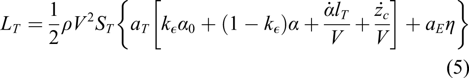
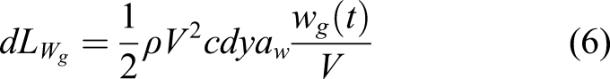
The effect of the vertical gust on the aerodynamics is a change of angle of attack. Thus, on the elastic wing, the increment of lift on a strip dy, located at distance y from the root, is given by
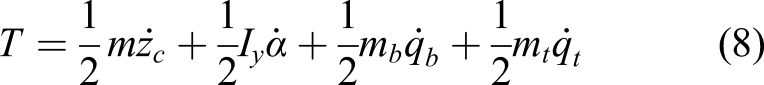
The kinetic energy due to the rigid motion and the dynamic motion is
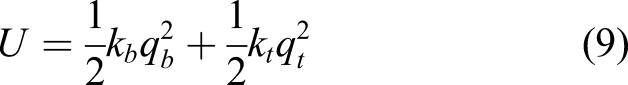
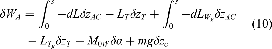
Finally, the virtual work done by lift forces and moment and the gravitational field force is
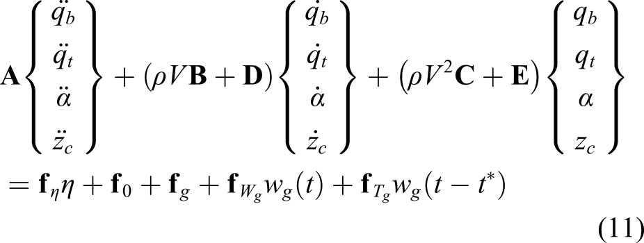
Exploiting the Lagrange formulation, the full aeroelastic equation in the classical second-order form is obtained as
Structural and aerodynamic model of an aircraft with a straight wing and folding wingtip (model two)
As mentioned above, the difference between the two models is the presence of the movable wingtip. The model of the aircraft with the folding wingtip can be obtained from the equations of model one, considering the additional contributions coming from the wingtip and taking into account that the elastic wing is composed of two contributions from wingspan s1 and wingspan s2, as shown in Figure 2. It is worth noting that in the region of s2 the chord is not constant, but is a function of the flare angle γ, of the elastic wingspan s and of the span position y. The geometric relation is
The wingtip is considered as a rigid body of mass m
wt
with the CM at
Considering small rotation of the wingtip and assuming the aerodynamic centre of the wingtip is at the quarter chord and halfway along its span, its vertical displacement is
The wingtip CM is at position
The kinetic energy due to the rigid and dynamic motion of the wingtip is
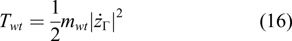
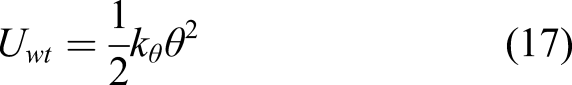
The total work done by the external force of the wingtip is

The Lagrange formulation is used to obtain the aeroelastic equation of motion as
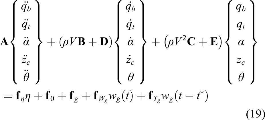
In contrast to the previous case, equation (11), an extra degree of freedom related to the wingtip rotation has been introduced.
In the following analysis, equations (11) and (19) have been solved using a 5 th order Runge–Kutta method with a 4 th order time step selection. 21
Gust model
Atmospheric disturbance models are categorized into two idealized categories: discrete gust and continuous turbulence.
22
In this article, a typical ‘1 - cosine’gust disturbance is considered, with a maximum gust velocity of
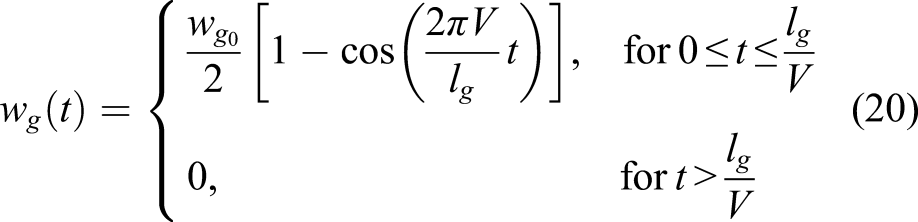
In the model validation section, gusts with a maximum gust velocity of 5 m/s and different lengths in the range of 20–200 m are considered.
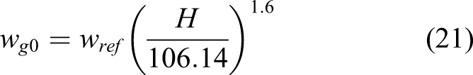
However, for the case of civil commercial aircraft, gusts wavelengths are varied between 18 m and 214 m (according to
22
), and the gust velocity is calculated as
Validation
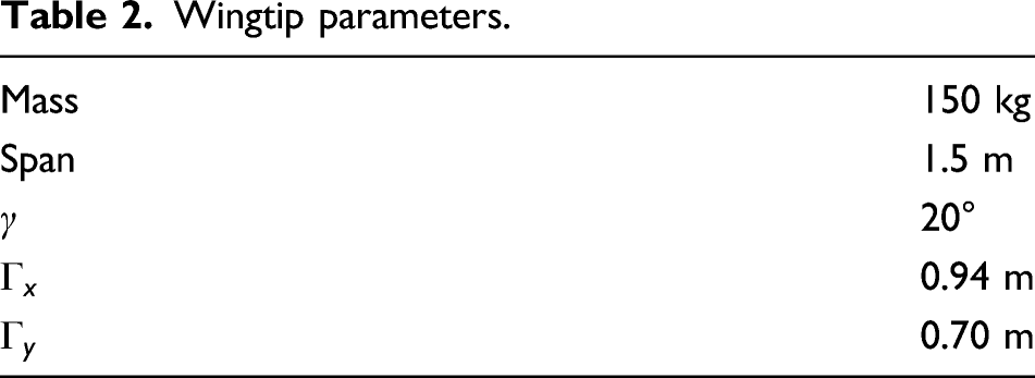
Aircraft parameters.
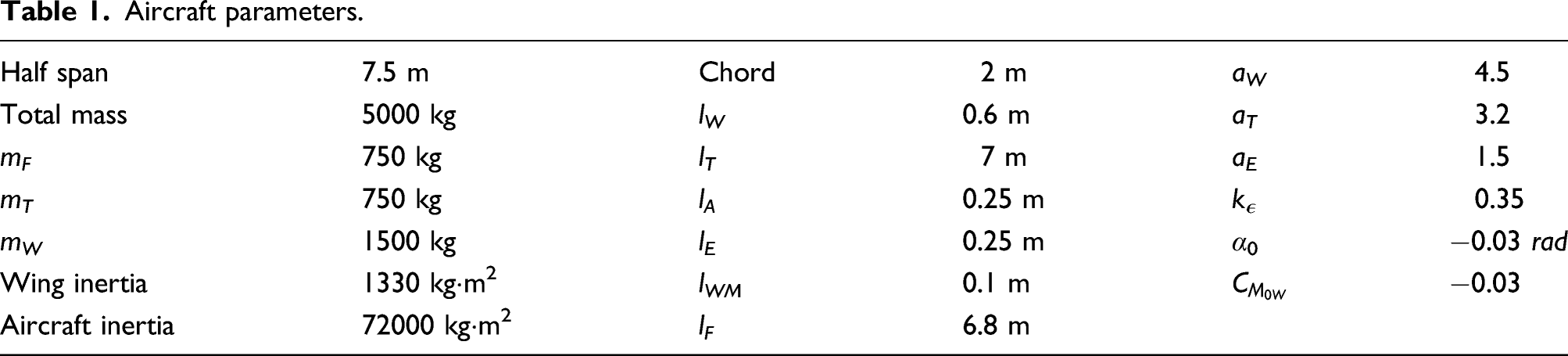
Wingtip parameters.
Comparison of different models
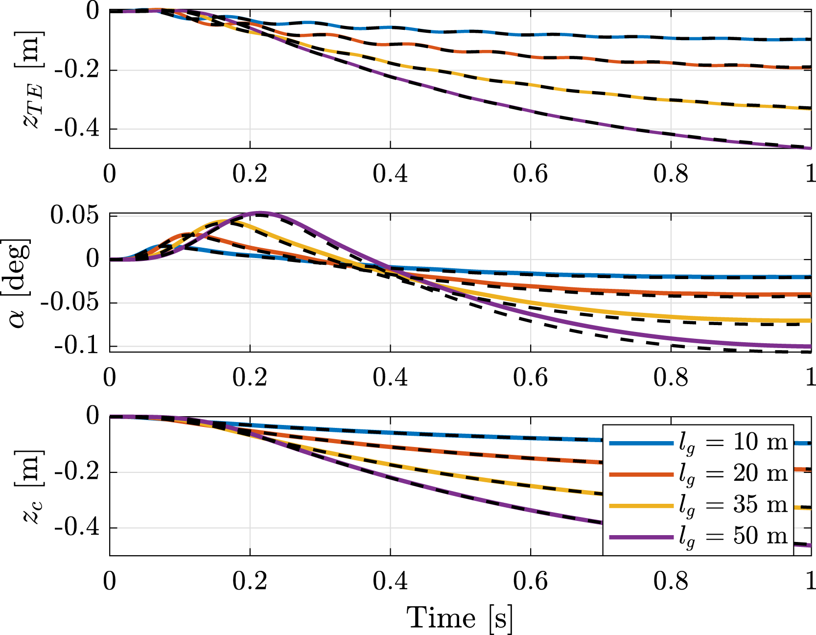
To validate the developed numerical model, the gust response of an elastic aircraft is obtained and compared with those reported by Wright et al. 3 for the gust response of an elastic aircraft (reference model). The reference model has three degrees of freedoms, the vertical displacement and the pitch angle of the aircraft centre of gravity and the torsional mode of the wing. In order to have a proper comparison, the natural frequencies of the elastic modes not considered in the reference model have been set to a high value and the torsional frequency is the same as the reference model. Therefore, in both models, the torsional mode frequency is set at 8.5 Hz, the bending mode at 56 Hz and the flapping mode at 61 Hz in model two.
The gust response in terms of vertical displacement of the trailing edge of the tip of the wing (z
TE
), angle of incidence (α) and vertical displacement of the centre of gravity (z
c
) are simulated for gusts with different wavelengths. Figures 3 and 4 compare the results of model one and model two, respectively, with the reference model (black dashed lines). The results show that the models give similar results. Comparison between model one (continuous line) and the reference model
3
(dashed lines). Comparison between model two with rigid connections (high stiffness) (continuous line) and the reference model
3
(dashed lines).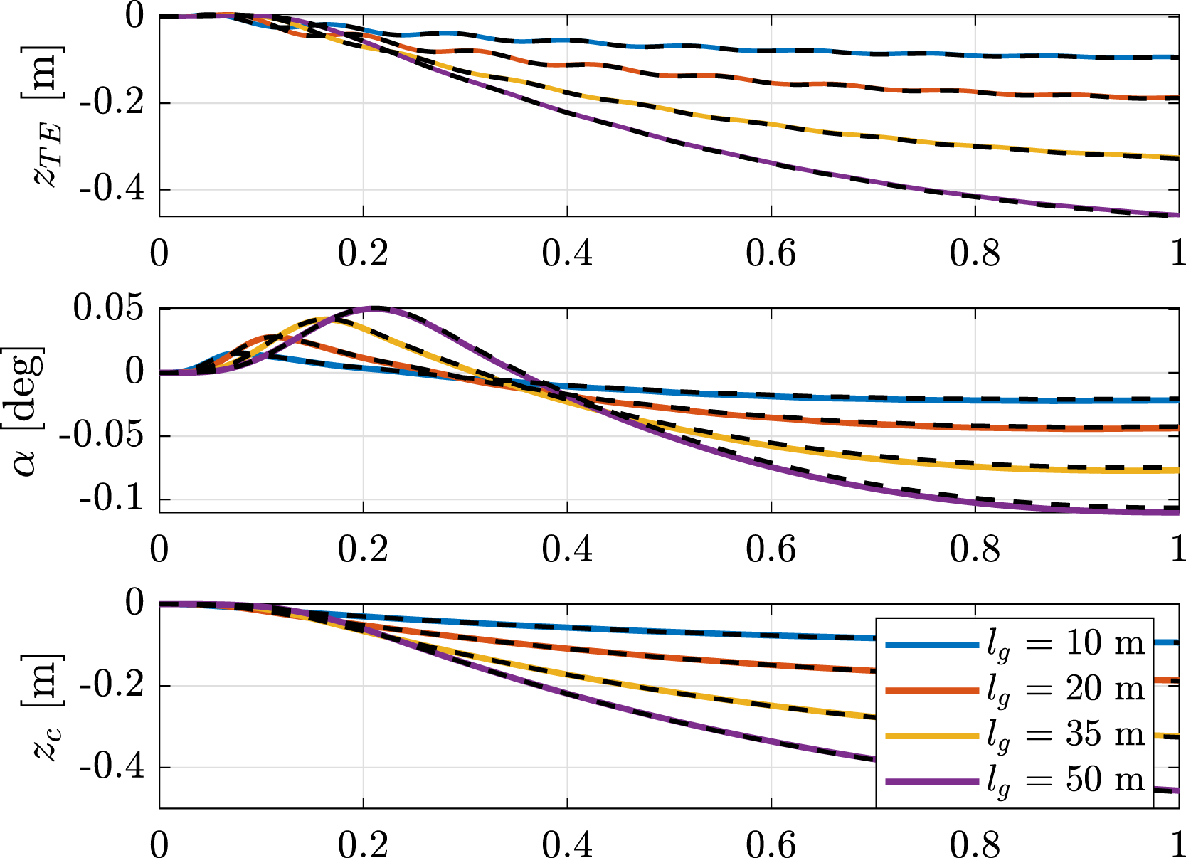
Model two gust response
This section presents the dynamic response of model two for different gust lengths and for various wingtip parameters. The modal stiffness has been set in order to obtain the frequency of the bending mode at 5 Hz and the frequency of the torsional mode at 8.5 Hz when a high value of the wingtip stiffness connection is considered.
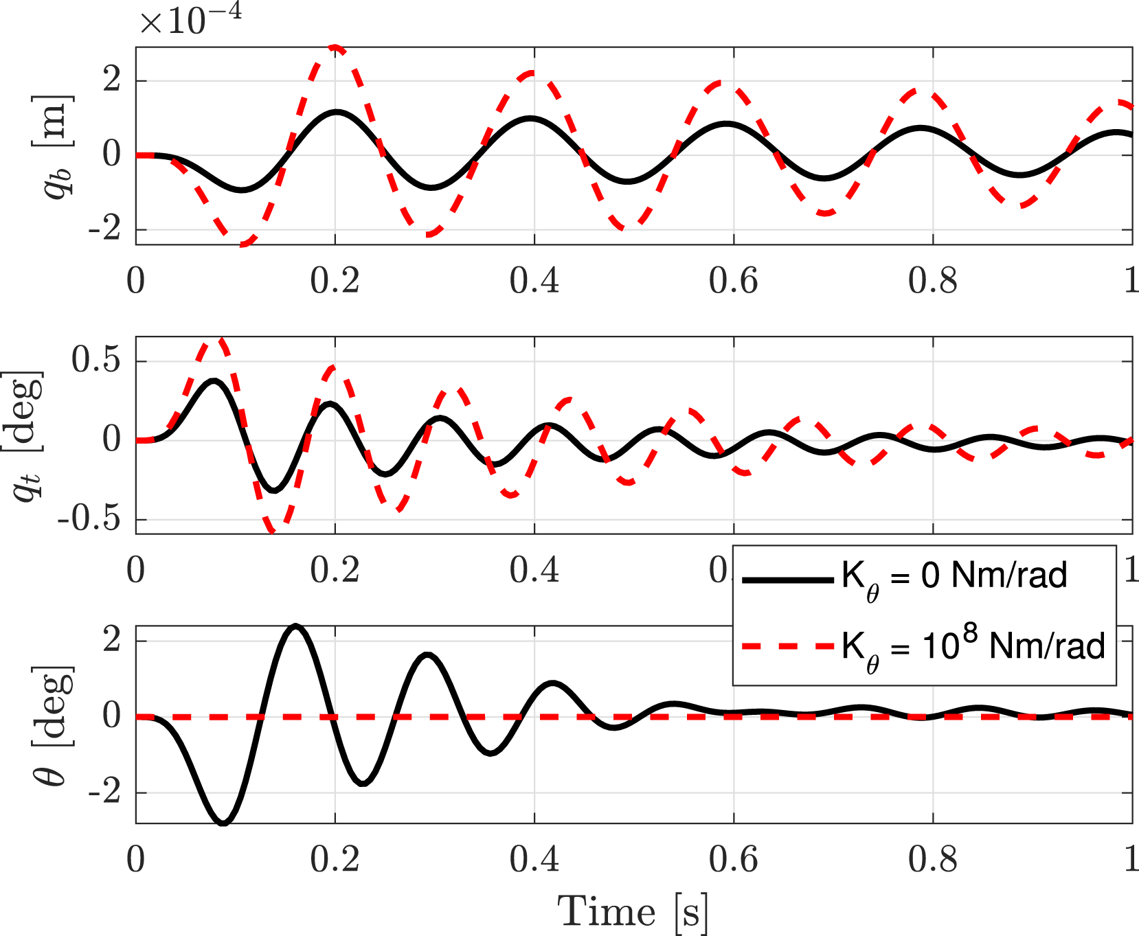
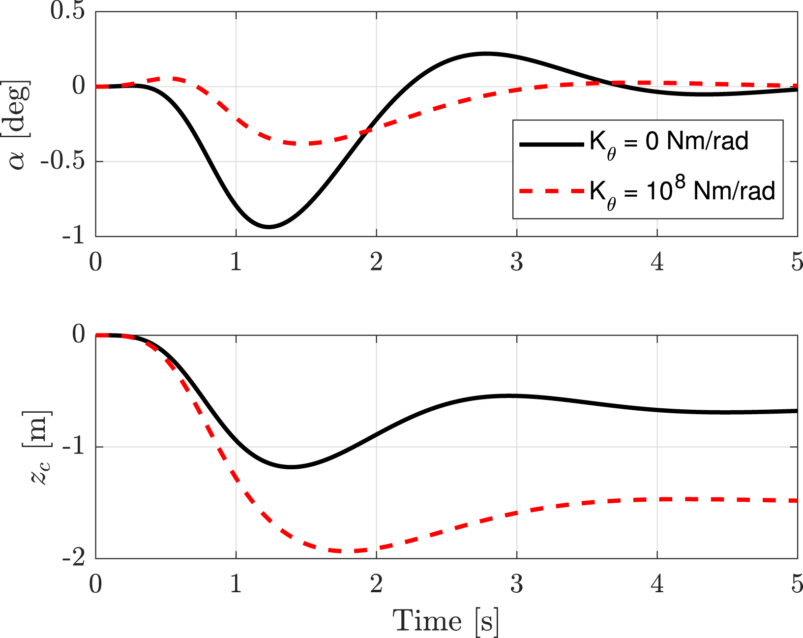
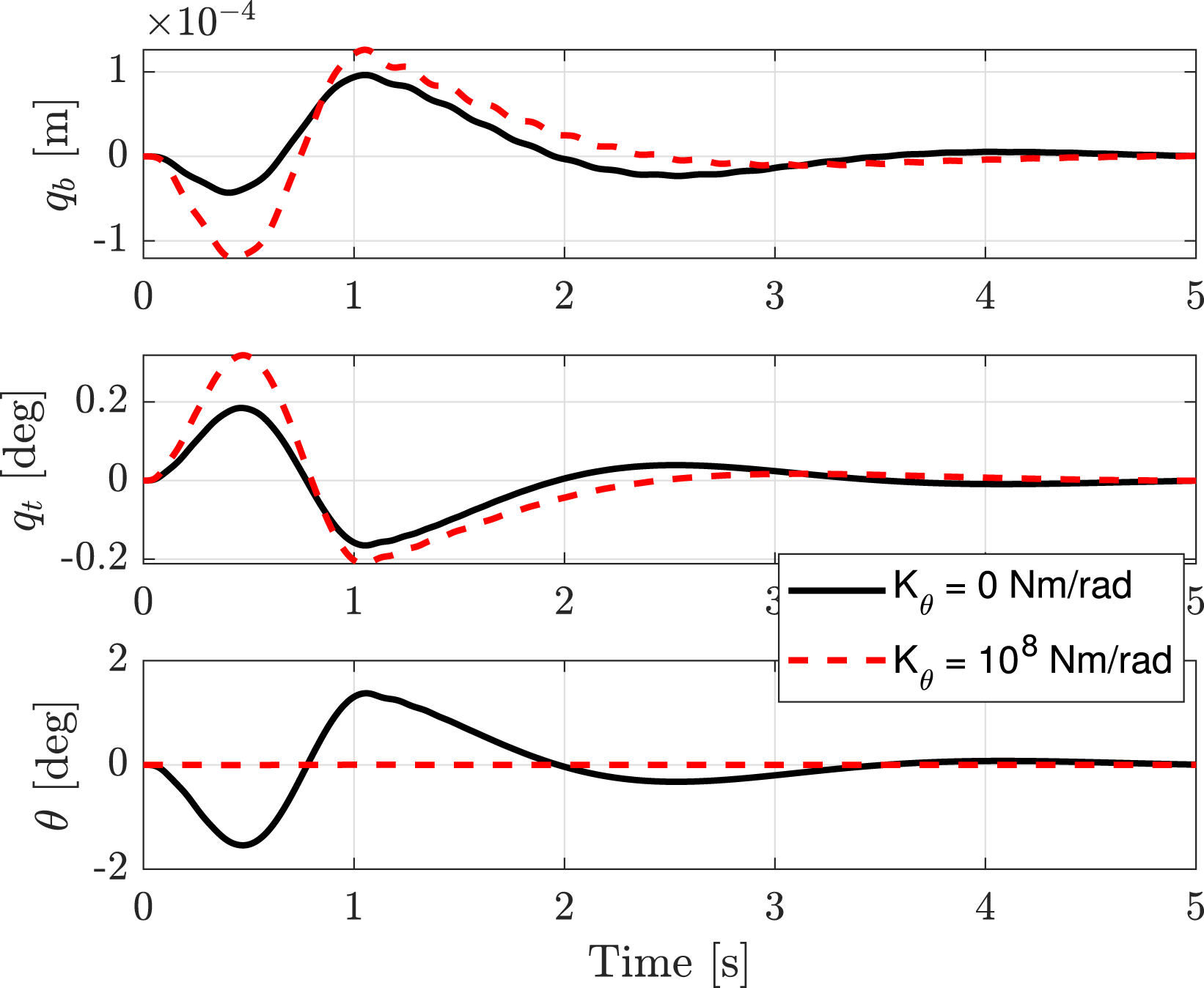
Figures 5–8 show the gust responses for low and high values of the stiffness connections between the wing and the wingtip. These two extreme cases represent the cases when the wingtip is free to rotate at the hinge (k
θ
= 0 Nm/rad) and the wingtip is rigidly attached to the wing (k
θ
= 108 Nm/rad). When the wingtip is free to rotate at the hinge, the heave mode is less exited and the pitch mode is more exited with respect to the case when the wingtip is rigidly attached to the wing. It is also possible to see that the zero stiffness connection reduces the torsional and bending mode responses. Rigid body responses to a 20 m 1-cos gust. Elastic mode responses to a 20 m 1-cos gust. Rigid body responses to a 200 m 1-cos gust. Elastic mode responses to a 200 m 1-cos gust.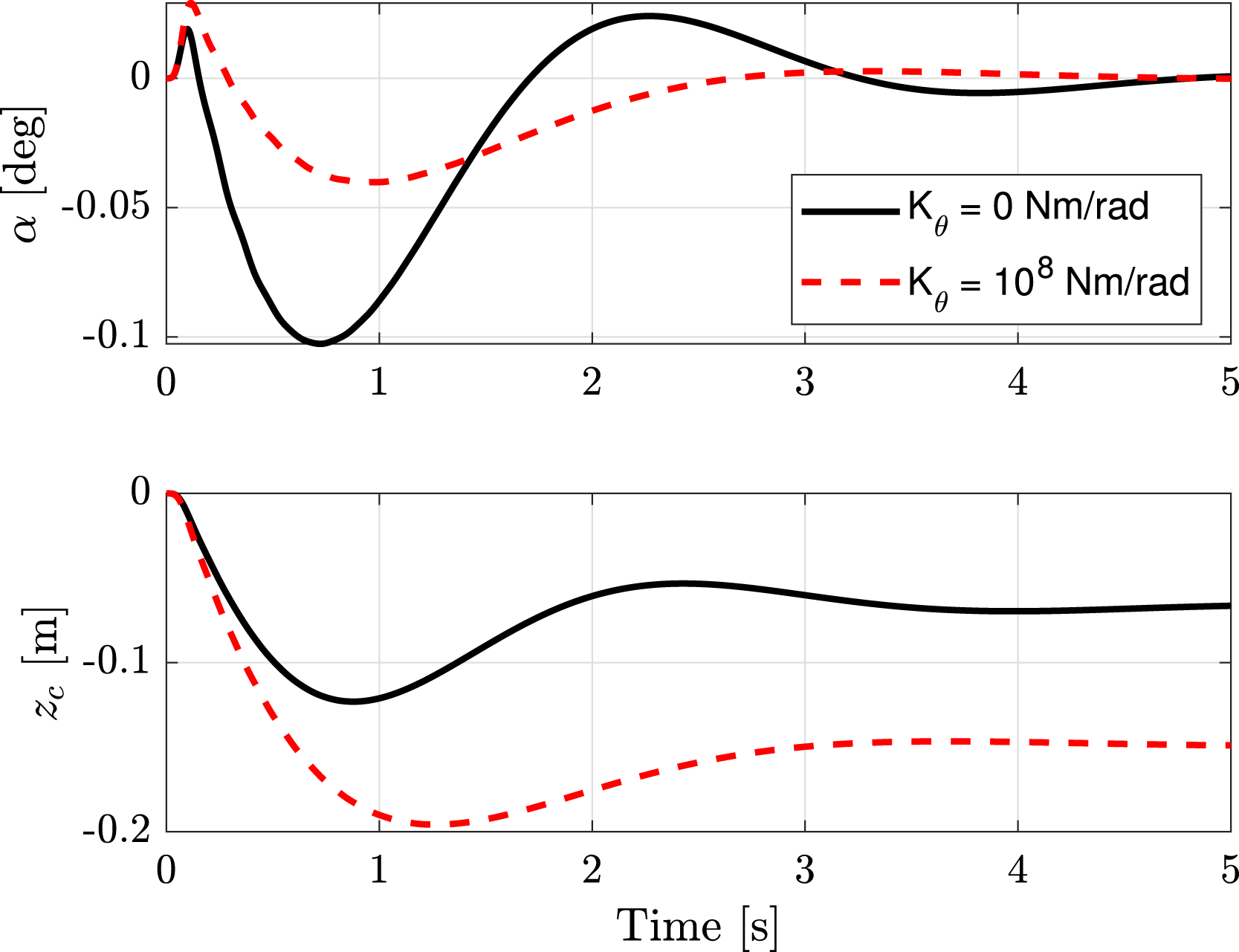
Figures 9–11 show the maximum and minimum values of the wing bending and torsional mode responses for values of the gust length between 20 m and 200 m. Figure 9 considers different cases of the wingtip stiffness connection, Figure 10 considers different cases of the flare angle (γ) and Figure 11 considers different positions, along the chordwise direction, of the wingtip CM (Γ
x
). Gust response for different gust lengths and values of stiffness connection. Gust response for different gust lengths and flare angle (k
θ
= 0 Nm/rad). Gust response for different gust lengths and positions of the wigtip CM (k
θ
= 0 Nm/rad).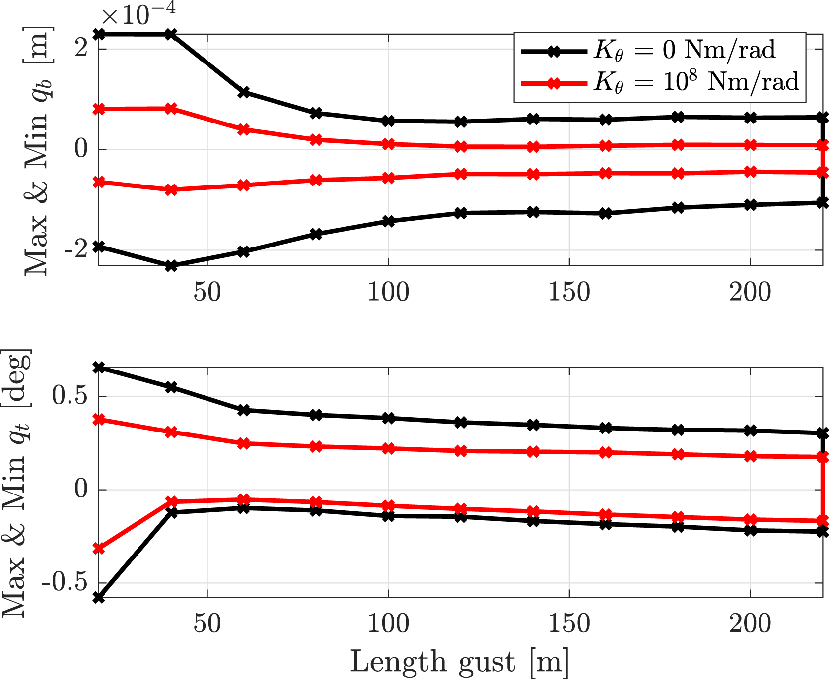
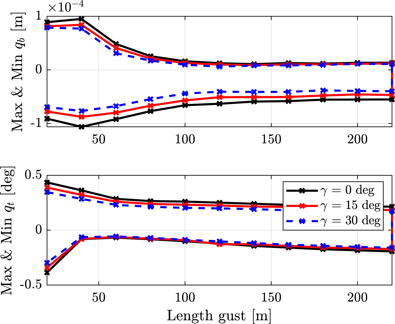
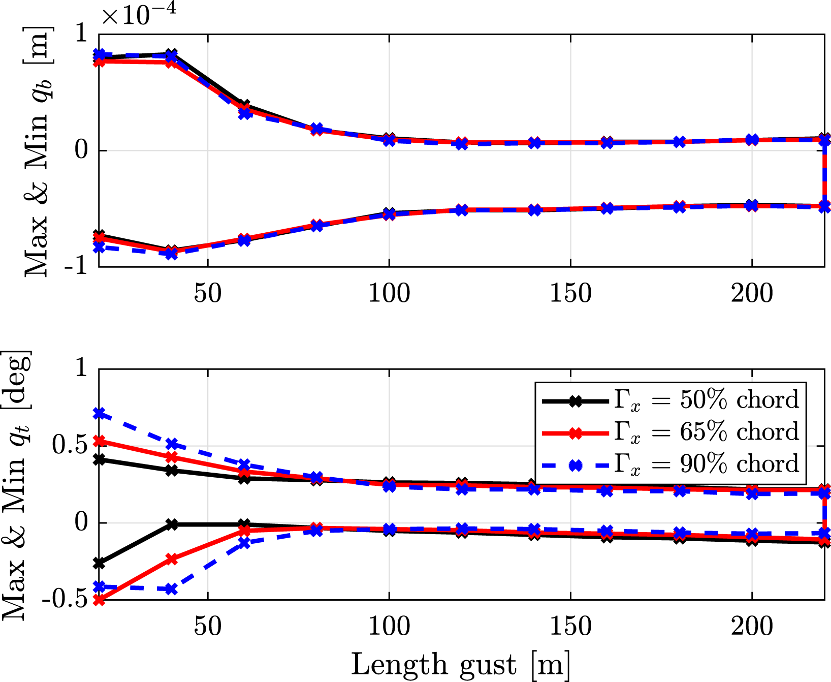
The hinge with zero torsional stiffness and the introduction of a larger flare angle are able to reduce the wing bending and the wing torsional mode response for all gust lengths. Furthermore, for gusts at high frequency, if the CM position is towards the trailing edge of the wingtip, the torsional mode has larger positive and negative peaks, but for gusts at low frequency, the torsional mode response has smaller peaks.
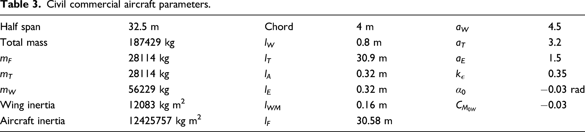
Civil commercial aircraft case
Civil commercial aircraft parameters.
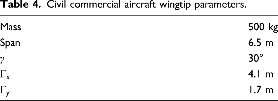
Civil commercial aircraft wingtip parameters.
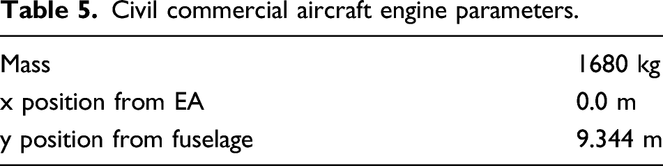
Civil commercial aircraft engine parameters.
Quantities of interest
The objective of a gust load alleviation system is the reduction of the stresses acting on the airframe. Since the most critical point for an aircraft is the connection between the wing and the fuselage, the wing root bending moment, the torsional moment and the shear force are taken as interesting quantities. The intensity of these forces and moments can be recovered from the aerodynamic, inertia and gravitational field force distribution acting on the wing and on the wingtip (see Appendix B).
Static trim solution
From the equation of motion of the full aircraft, equation (19), it is possible to calculate the static deformation of the aircraft. The degrees of freedom that have to be calculated are the bending and torsional modes of the wing, the deflection of the wingtip, the pitch of the complete aircraft and the deflection of the elevator. Although the vertical displacement of the centre of gravity of the aircraft is a degree of freedom of the system, its value is imposed a priori and will affect the air density. The deflection of the elevator has been introduced as an unknown of the trim calculation in order to enforce the vertical balance of forces.
Figures 12 and 13 show the trim configuration for different values of the stiffness on the folding hinge in terms of pitch angle of the aircraft (α), elevator angle (η), wingtip deflection (θ) and the interesting quantities at 200 m/s at sea level. For high values of the stiffness connection, which represents the wingtip rigidly connected to the elastic wing, the wingtip is not rotating. For lower values of the stiffness connection, the wingtip rotates in the opposite direction to gravity and consequently produces a lower lift. The vertical equilibrium is respected through an increase of the pitch of the aircraft. For different trim configurations, the elevator deflection is imposed to keep the tailplane lift constant. In order to ensure that for different trim configurations, the tailplane generates the same lift and the elevator deflection changes accordingly. Trim angles for different values of wingtip stiffness connection: fuselage incidence (α), elevator angle (η) and wingtip deflection (θ). Interesting quantities in trim for different values of wingtip stiffness connection.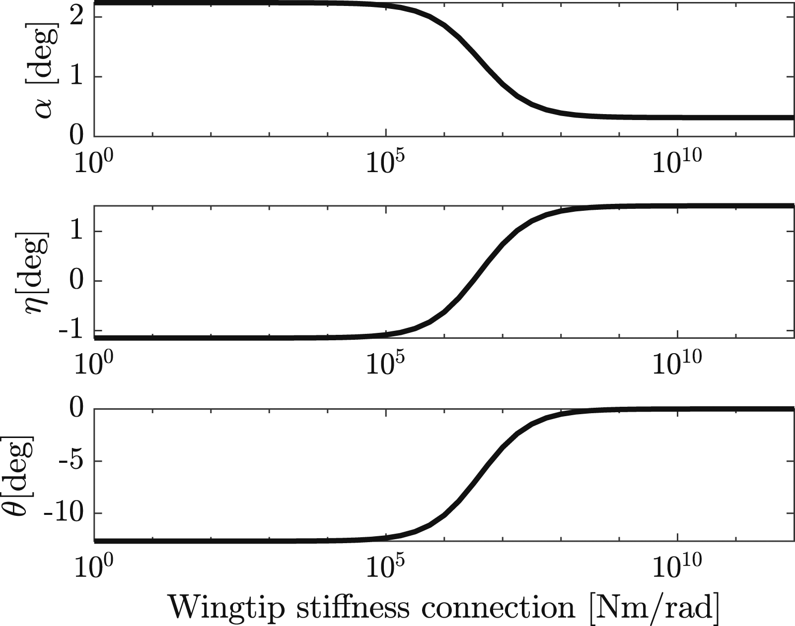
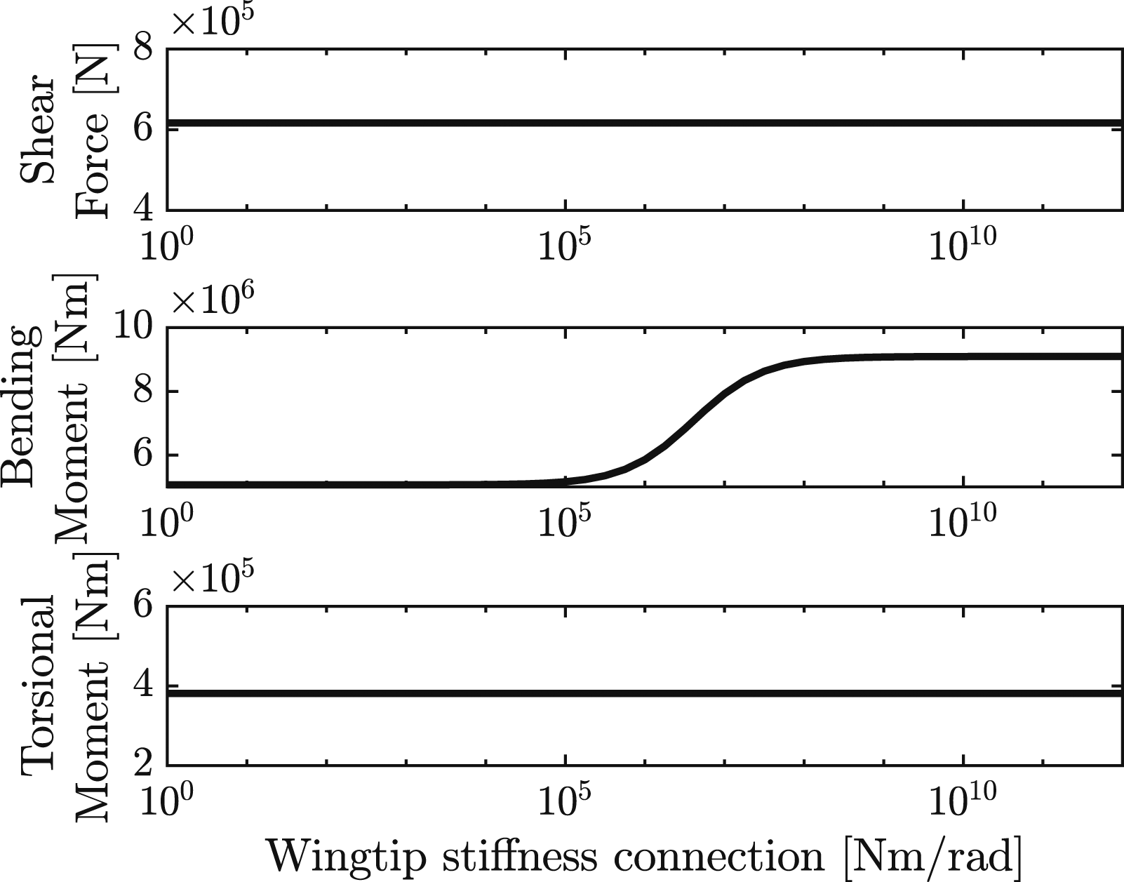
The shear force is not varying for different values of the stiffness connection because the total lift generated by the wing and weight of the wing are constant. The distance of the aerodynamic centre from the elastic axis is constant; therefore, a different lift distribution has no effect on the torsional moment but it modifies the bending moment; indeed, the increment of the stiffness connection produces a greater lift on the wingtip and therefore the bending moment increases.
Multi-objective optimization
Previous studies have shown the importance of the flare angle and wingtip weight. 11 24 In this work, several optimizations are performed to obtain the optimal position of the wingtip CM, the flare angle and the wingtip span. The MATLAB GA Toolbox is used for optimization because of its reliability in finding global optimal solutions even in cases where the objective functions have several local maxima and minima. In this work, parallel computing inside the GA is used to speed up the optimization process. It is worth noting that the GAs require lower and upper bounds on the design variables and they are stochastic search algorithms that can give different results on repeating the optimization. 25
In the optimization process, different optimization functions, able to minimize all the interesting quantities, have been considered. In this work, the optimization is performed in terms of wing root internal loads, but in the real case, the objective is the wing weight reduction which leads to the reduction in the fuel burn. To estimate the wing weight or the fuel burn, a detailed model of a specific aircraft is required and the results of the optimizations will be model dependent. To overcome this problem, it has been decided to perform multi-objective optimization.25,26
In the following sections, the results of four different multi-objective optimizations considering the whole flight envelope are reported, and in each case, different parameters are considered. In all the multi-objective optimizations, it has been considered the hinge connection between wing and wingtip without any spring. The objective of the optimization is to find the optimal position of the wingtip CM, flare angle and wingtip span (first section), the optimal position of the wingtip CM and flare angle (second section), the optimal position of the wingtip CM fixing the flare angle at 30° (third section) and the optimal position of the wingtip CM fixing the flare angle at 20° (fourth section). After the optimizations different technique to increase the flutter speed will be presented.
Optimization: set-up
In the following subsections, a number of optimizations are performed for the whole flight envelope and the entire gusts frequency range. A set of 104 flight configurations has been defined, as shown in Figure 14, and the response to 15 different gusts with gust lengths in the range of 18 m–214 m has been considered. Flight configurations considered, worst cases wingtip rigidly connected to the wing and free to rotate.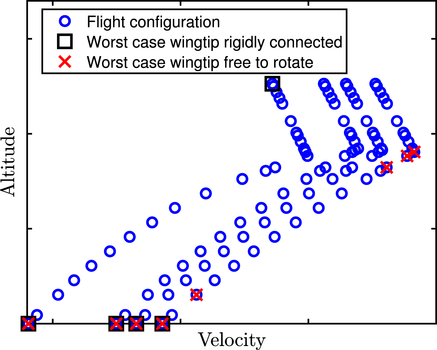
Before performing the optimizations, two extreme cases have been analyzed, the wingtip rigidly connected to the wing and the wingtip free to rotate in the hinge. In each analysis, the shear force, the bending moment and the torsional moment time histories have been calculated. The shear force and bending moment have been plotted against each other. The convex hull in these two cases has been calculated and is shown in Figure 15. The same procedure has been repeated with the bending moment and the torsional moment. Figure 16 shows the results. Figure 14 shows the flight configurations associated with the point on the convex hulls for both extreme cases. Comparison of the shear force-bending moment convex hull obtained with the wingtip rigidly connected to the wing and the wingtip free to rotate. Comparison of the shear force-torsional moment convex hull obtained with the wingtip rigidly connected to the wing and the wingtip free to rotate.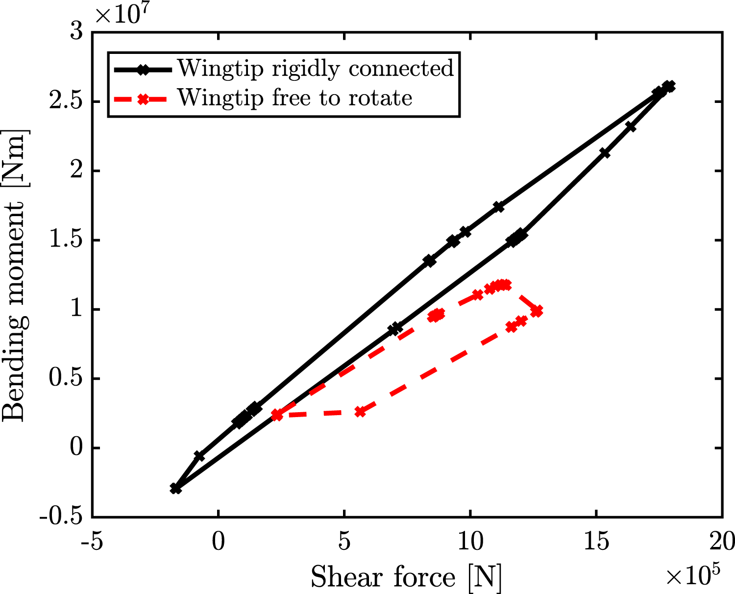
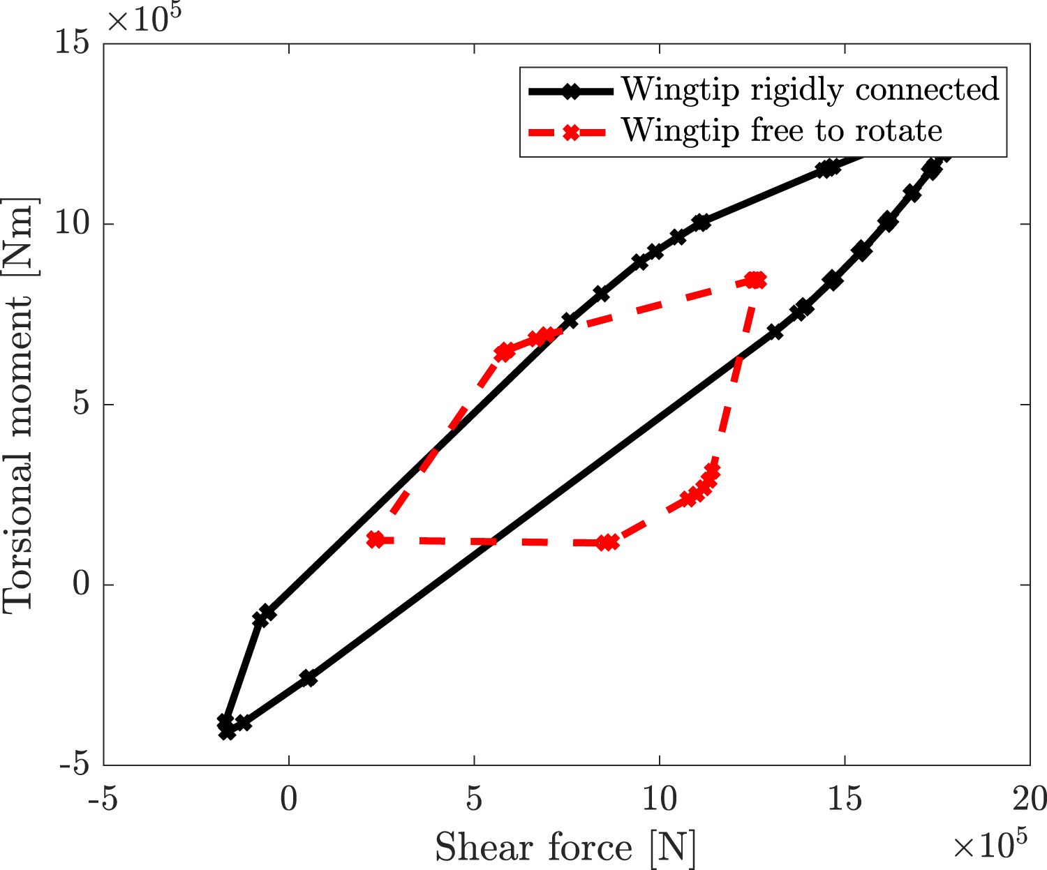
The case of null stiffness connection between the wing and the wingtip has been considered as a reference configuration for the optimization processes. The flight configuration and the gust length related to each point in both the convex hulls of the reference configuration have been considered as critical cases for the following analyses.
The following fitness functions have been considered for the multi-objective optimization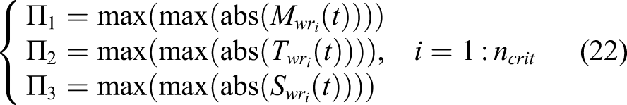
A. Optimal parameters: wingtip CM position, flare angle and wingtip span
In this section, multi-objective optimization has been performed considering the coordinated of wingtip CM position, the flare angle and the wingtip span as optimal parameters. The lower and upper bounds of the flare angle are 0° and 45°, respectively, and the wingtip CM position is constrained to lie in any position inside the current wingtip. In each iteration, the wingtip weight has been calculated considering as unit span weight of 100 kg/m and the elastic wing weight is corrected to have the total wing weight constant. The model developed does not consider the aerodynamic stall, so, a constraint on the maximum angle of attack has been introduced. The upper bound of fuselage angle of attack is considered as 7° and it ensures that the optimization does not converge on high value of wingtip span that needs high angle of attack to ensure equilibrium. Figure 17 shows the results. Figure 17(a) shows the fitness function values corresponding to the Pareto points and the fitness function values related to the minimum bending moment, torsional moment and shear force. Moreover, the fitness function points have been interpolated by a surface, and by rotating the figure, it is possible to obtain a better view of its structure, as shown in Figures 17(b) to (d). The results show a wild range of variation for all the interesting quantities. Multi-objective optimization results, optimization parameters: wingtip centre of mass position, flare angle and wingtip span.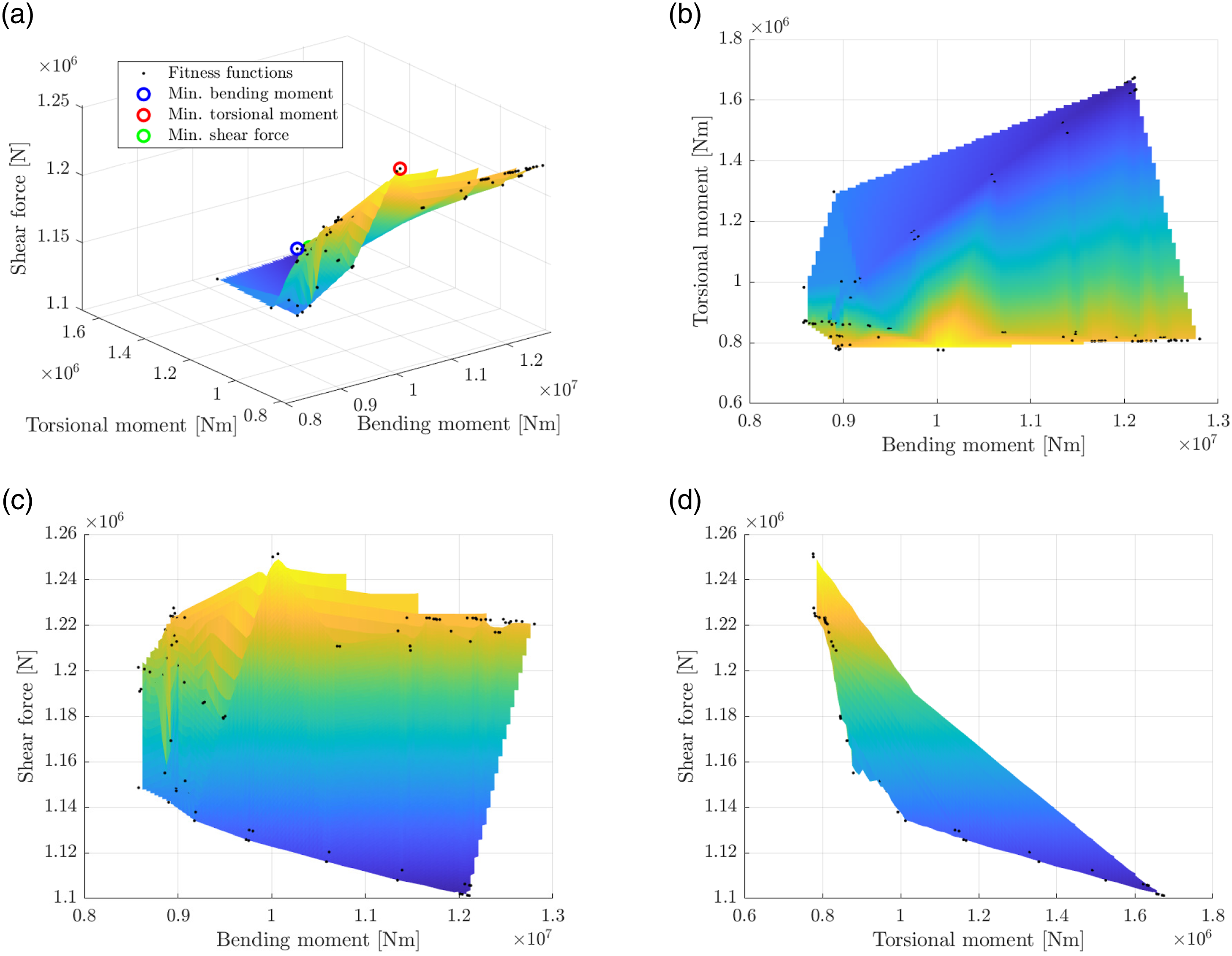
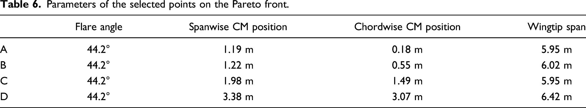
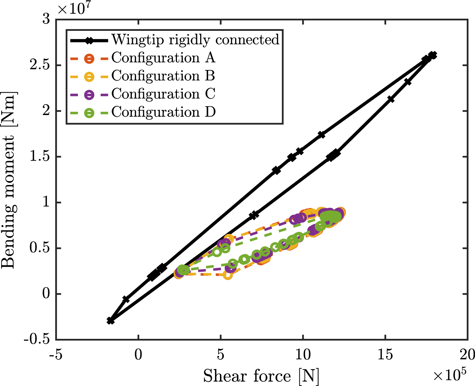
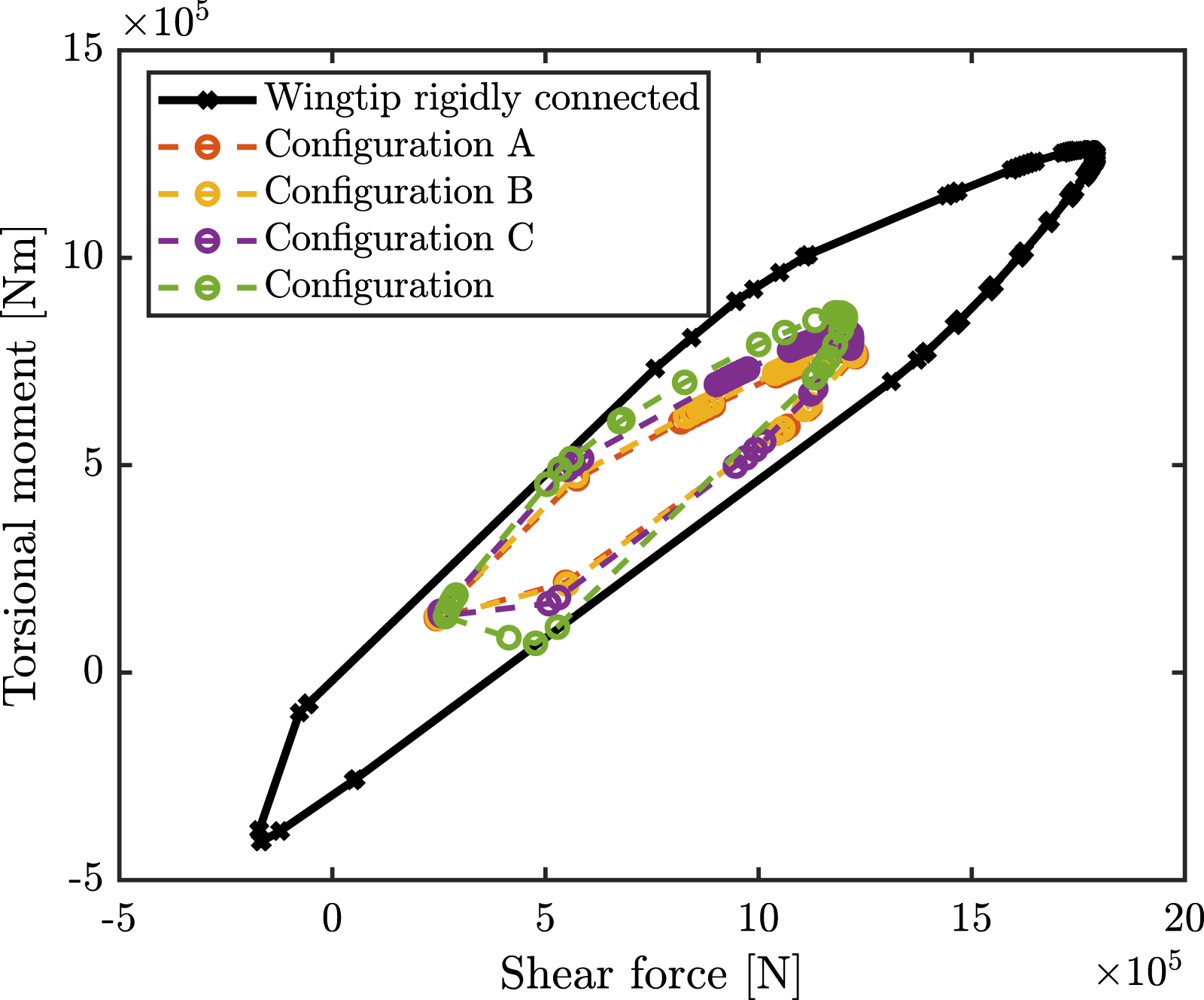
Figure 18 shows the fitness function points of Figure 17(b). In Figure 18, four fitness function values have been considered and the corresponding parameters are reported in Table 6. In the configuration selected, the flare angle is always 44.2°, the spanwise position of the CM is between 1.19 m and 3.38 m (corresponding to the 20% and 53% of the total wingtip span), the chordwise position of the CM is between 0.18 m and 3.38 m (corresponding to the 5% and the 85% of the chord) and the wingtip span is between 5.95 m and 6.42 m (corresponding to the 18% and the 20% of the total wingspan). Figures 19 and 20 show the convex hull in the case of wingtip rigidly connected and the optimized configurations tested on the whole flight envelope. As in the previous cases, the configurations selected can reduce all the quantities of interest with respect to the case of wingtip rigidly connected to the wing. The maximum peak of the bending moment is reduced by 62%–63%, the maximum peak of the torsional moment is reduced by 31%–38% and the maximum peak of the shear force is reduced by 31%–33%. Pareto front on the bending moment and torsional moment plane at the optimal compromise. Parameters of the selected points on the Pareto front. Shear force-bending moment convex hull for the rigid connection and for optimized configurations. Shear force-torsional moment convex hull for the rigid connection and for optimized configurations.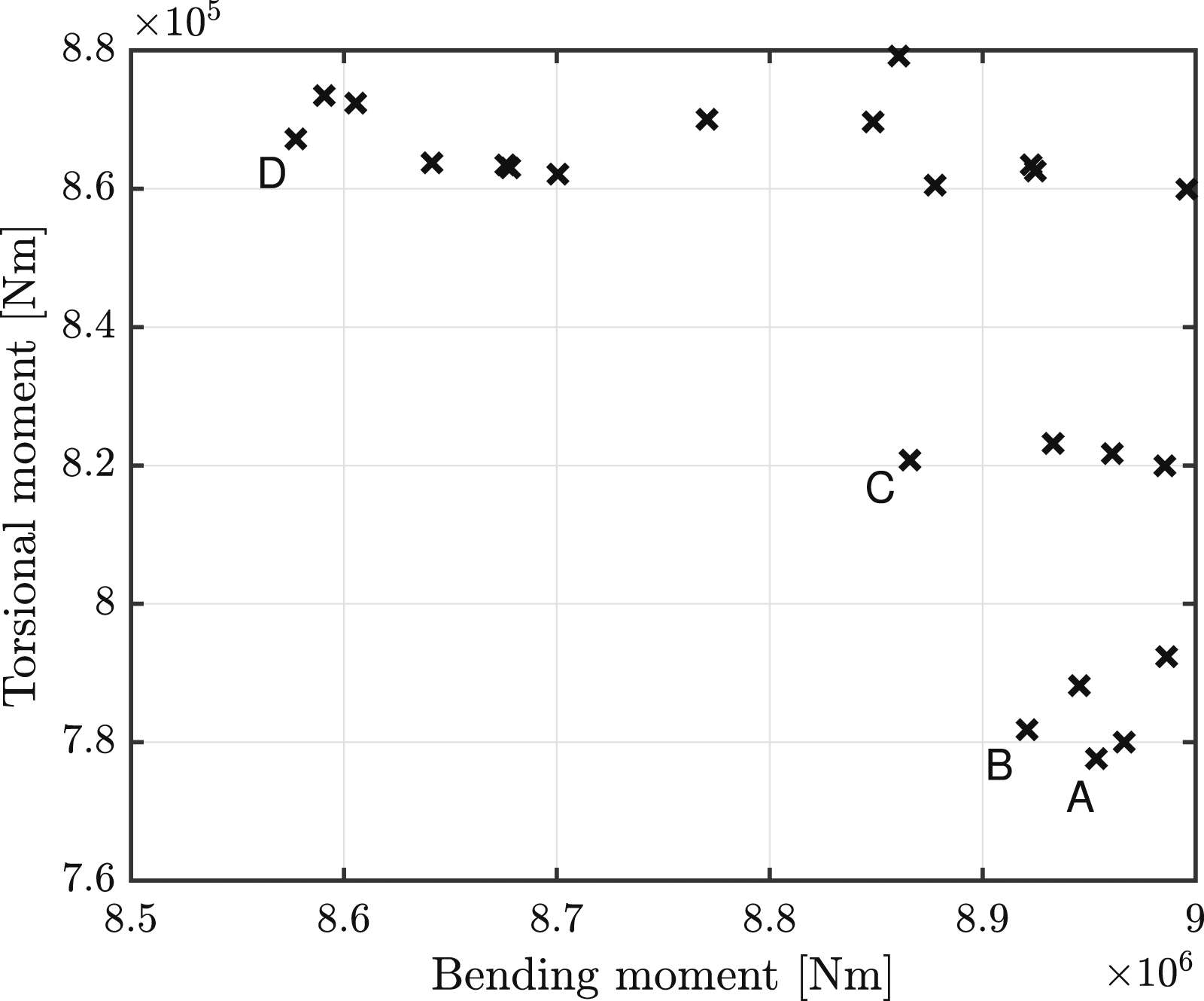
B. Optimization parameters: wingtip CM position and flare angle
The optimization parameters considered in this case are the wingtip CM position and flare angle. The lower and upper bounds of the flare angle are 0° and 45°, respectively, and the CM is constrained to lie in any position inside the wingtip. Figure 21 shows the results. Figure 21(a) shows the fitness function values corresponding to the Pareto points, the interpolated surface and the fitness function values related to the minimum bending moment, torsional moment and shear force. Figure 21(a) shows the Pareto front and Figures 21(b) to (d) show Figure 21(a) from different views. Figure 21 shows a wide range of variation in the bending moment and torsional moment. Moreover, the Pareto front shows a corner representative of an optimal compromise between the bending moment and the torsional moment. Figures 21(c) and (d) show a small variation in the shear force. Multi-objective optimization, optimization parameters: wingtip centre of mass position and flare angle.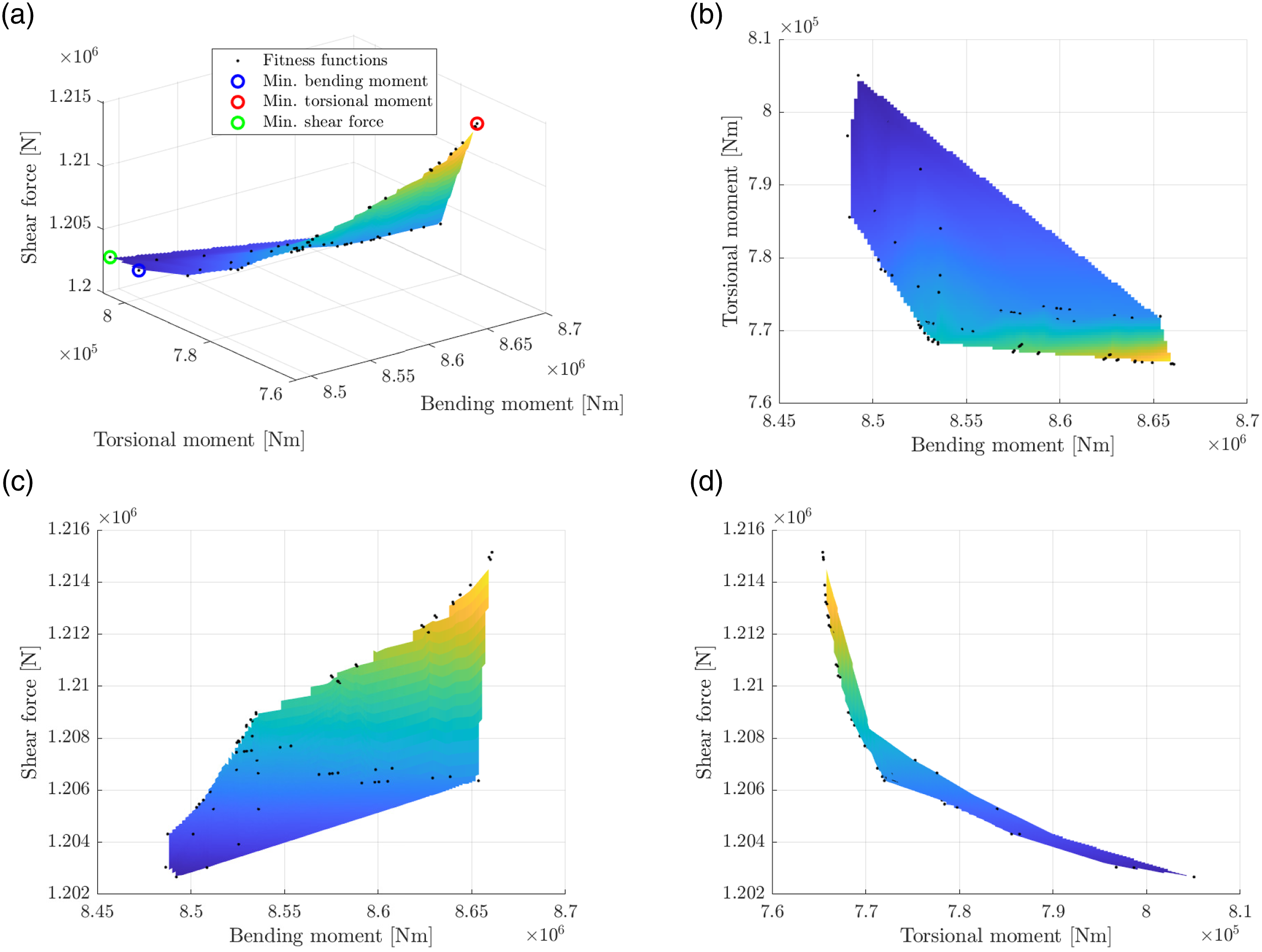
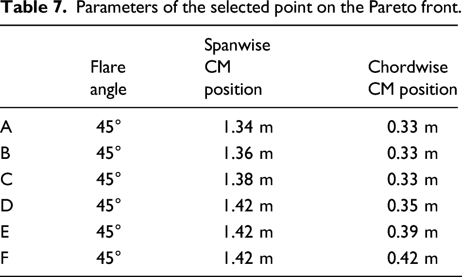
Figure 22 shows the fitness function points of Figure 21(b) in the proximity of the corner of the Pareto points. In Figure 22, six fitness function values have been selected and the corresponding parameters are reported in Table 7. In all of the configurations, the optimal flare angle is 45°, the optimal spanwise position of the CM is between 1.34 m and 1.42 m (corresponding to the 21% and 22% of wingitp span) and the optimal chordwise position of the CM is between 0.33 m and 0.42 m (corresponding to the 8.25% and 10.5% of chord). Pareto front on the bending moment and torsional moment plane at the optimal compromise. Parameters of the selected point on the Pareto front.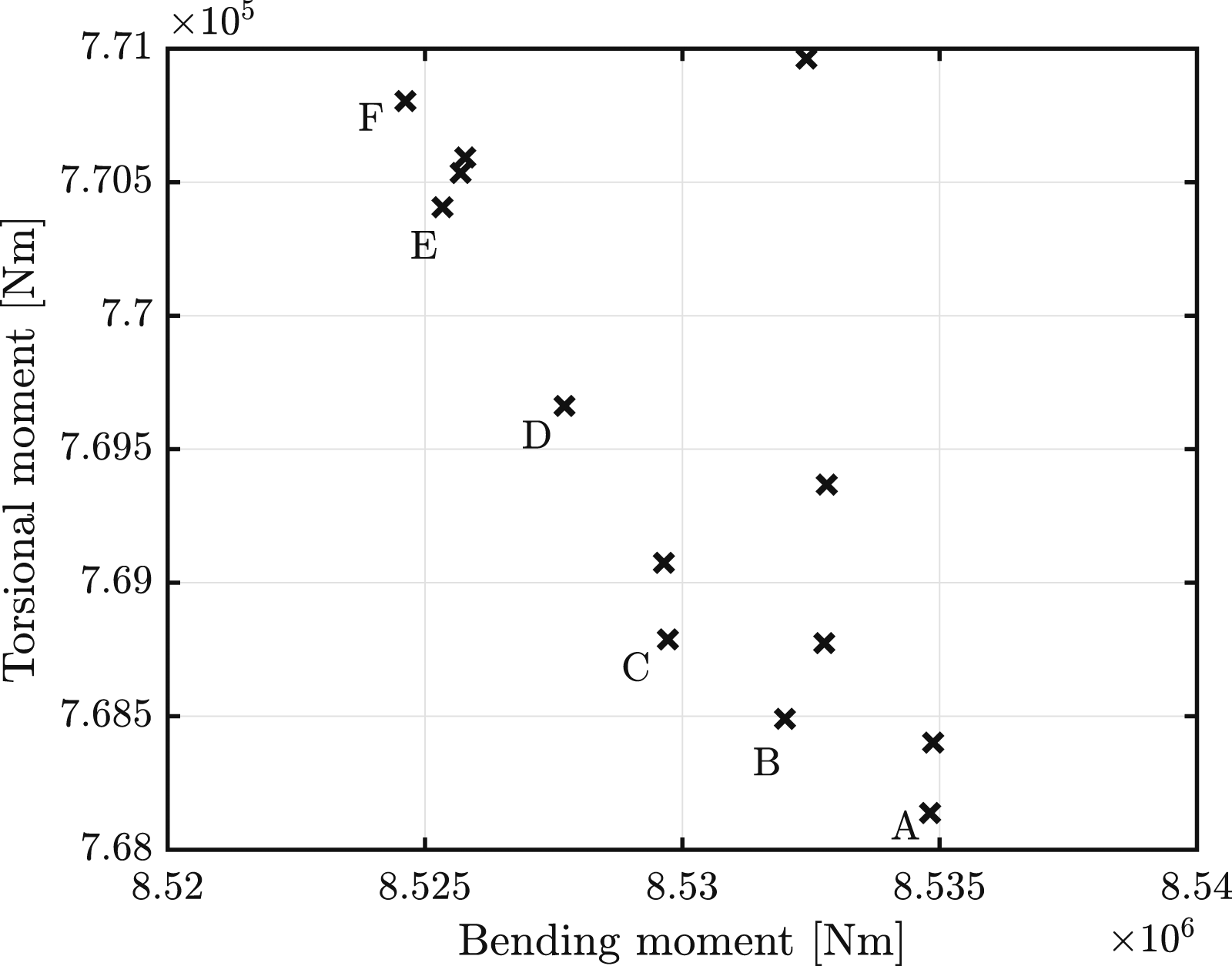
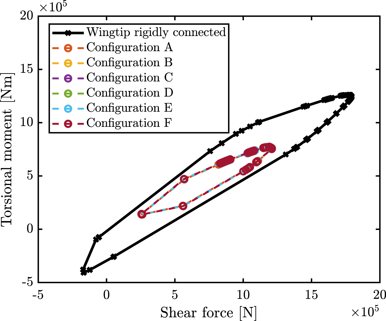
Figures 23 and 24 show the convex hull in the case of wingtip rigidly connected and the optimized configurations tested on the whole flight envelope. The configurations selected can reduce all the quantities of interest with respect to the case of wingtip rigidly connected to the wing. The higher reduction is on the bending moment, where the reduction of the maximum peak is 67%, the maximum peak of the torsional moment is reduced by 39% and the maximum peak of the shear force is reduced by 33%. Shear force-bending moment convex hull for the rigid connection and for optimized configurations. Shear force-torsional moment convex hull for the rigid connection and for optimized configurations.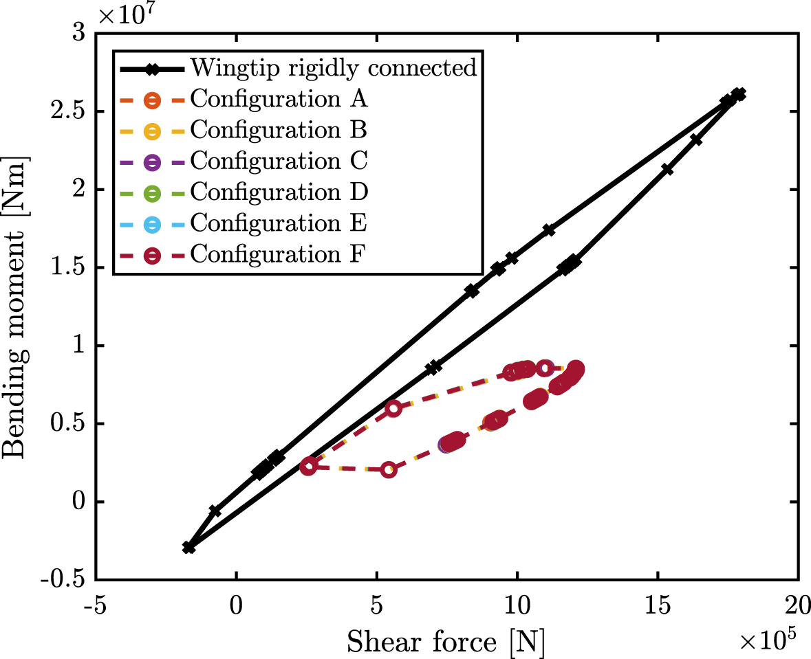
C. Optimal parameters: CM positions with flare angle fixed at 30°
The multi-objective optimization has been repeated considering the x and y coordinates of the wingtip CM position as optimal parameter. In this case, the flare angle is fixed at 30°. The wingtip CM is constrained to lie in any position inside the wingtip. Figure 25 shows the results. Figure 25(a) shows the fitness function values corresponding to the Pareto points, the interpolated surface and the fitness function values related to the minimum bending moment, torsional moment and shear force. Figures 25(b) to (d) show Figure 25(a) from different views. Comparing Figures 25(c) and (d) with Figures 21(c) and (d), one can observe higher variation in the shear force. In Figure 25(b), the Pareto front has a corner representative of the optimal compromise between bending moment and torsional moment. Multi-objective optimization, optimization parameters: wingtip centre of mass position with a 30° flare angle.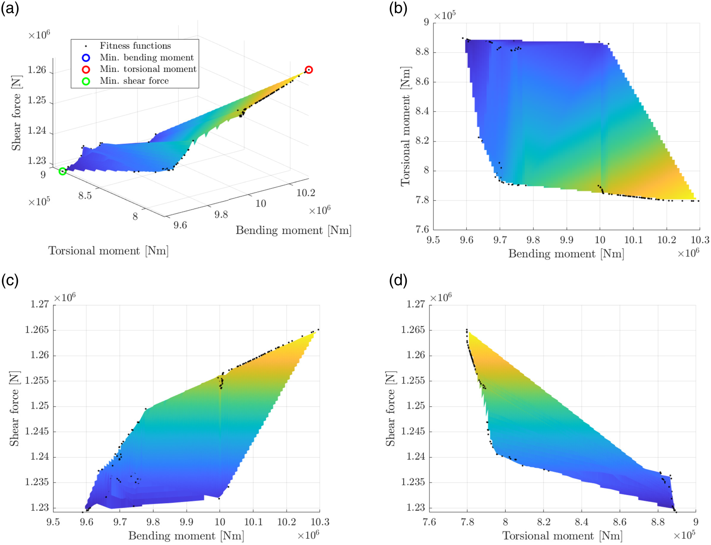
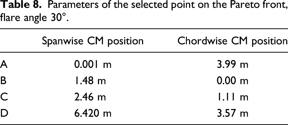
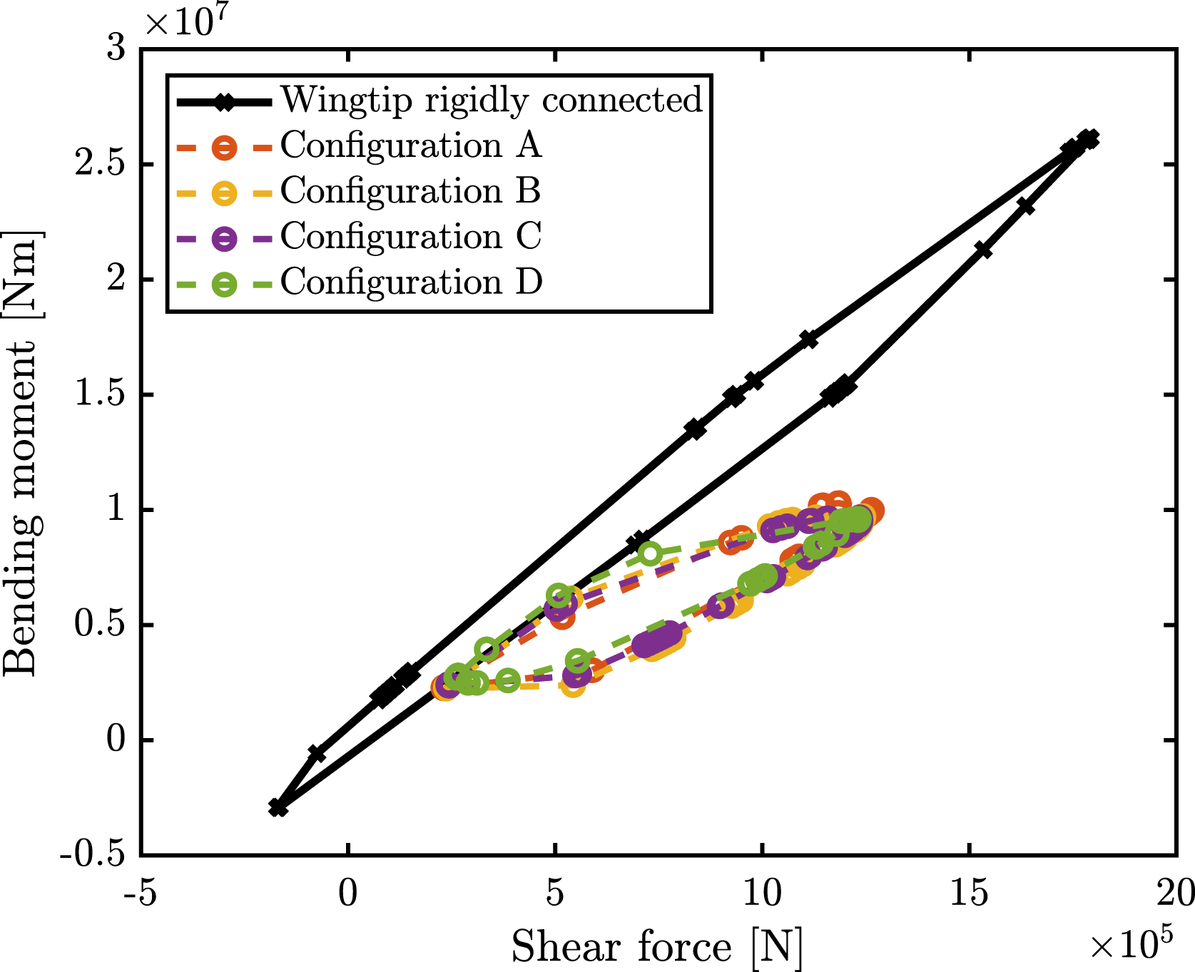
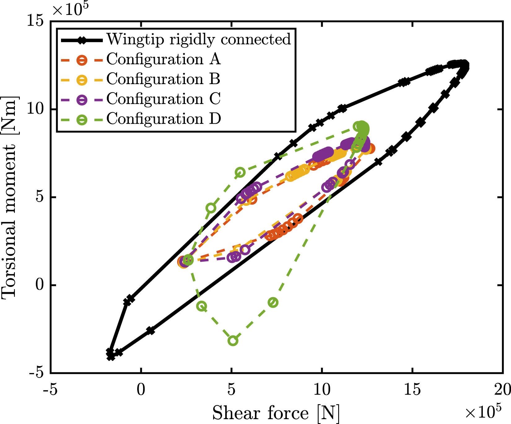
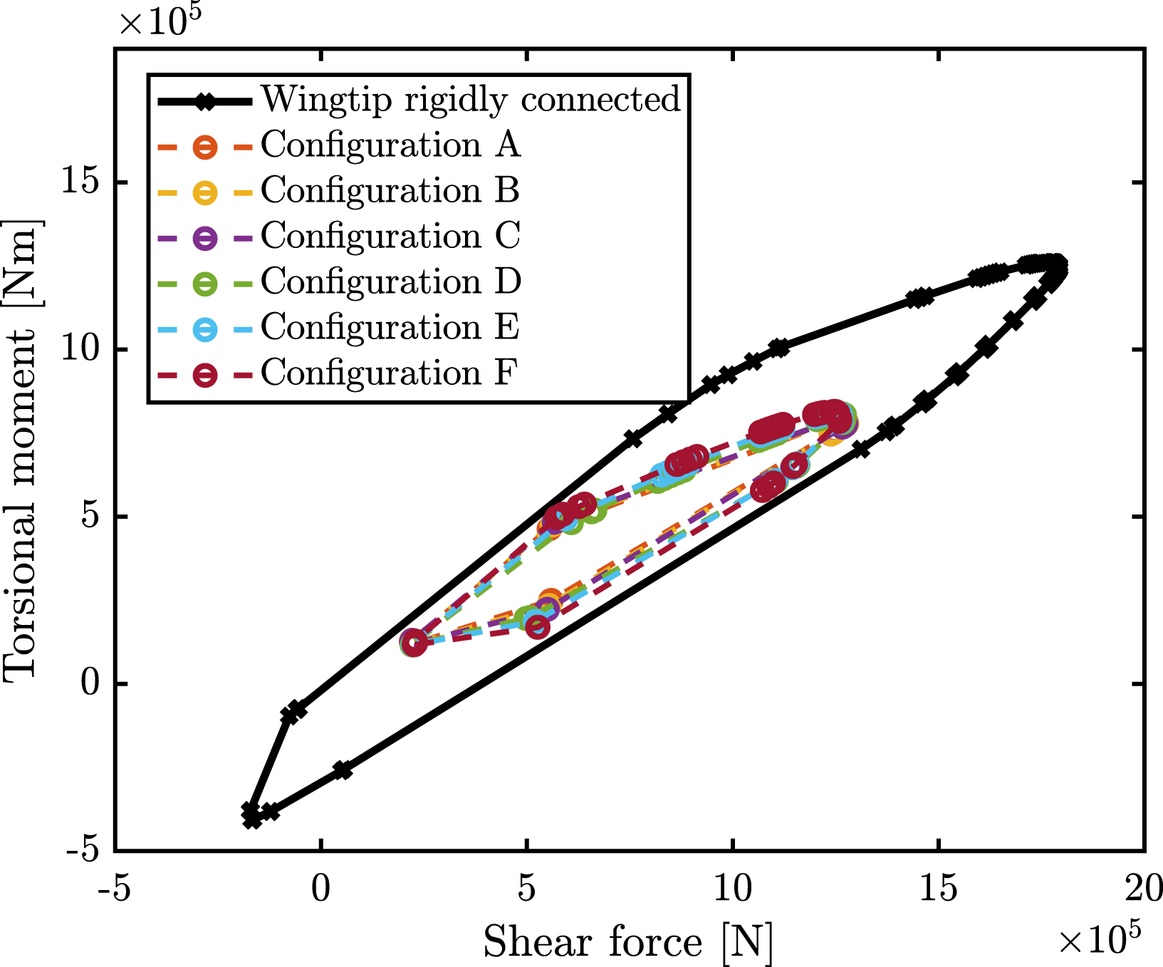
Figure 26 shows the fitness function points of Figure 25(b). In Figure 26, four fitness function values have been considered and the corresponding parameters are reported in Table 8. Configuration A is the configuration that minimizes the torsional moment and configuration D minimizes the bending moment. Configurations B and C represent a compromise between the torsional moment and the bending moment. In the configuration selected, the spanwise and the chordwise position of the CM covers a wide range of variation. Figures 27 and 28 show the convex hull in the case of wingtip rigidly connected and the optimal configurations tested on the whole flight envelope. As in the previous cases, the configurations selected can reduce all the quantities of interest with respect to the case of wingtip rigidly connected to the wing. From configuration A to D, the maximum peak of the bending moment reduced and the maximum peak of the torsional moment increased. The maximum peak of the bending moment is reduced by 61% in configuration A and 63% in configuration D. The maximum peak of the torsional moment is reduced by 28% in configuration D and 38% in configuration D. The maximum peak of the shear force is reduced by 29% in configuration A and 31% in configuration D. Pareto front on the bending moment and torsional moment plane at the optimal compromise, flare angle 30° Parameters of the selected point on the Pareto front, flare angle 30°. Shear force-bending moment convex hull for the rigid connection and for optimized configurations. Shear force-torsional moment convex hull for the rigid connection and for optimized configurations.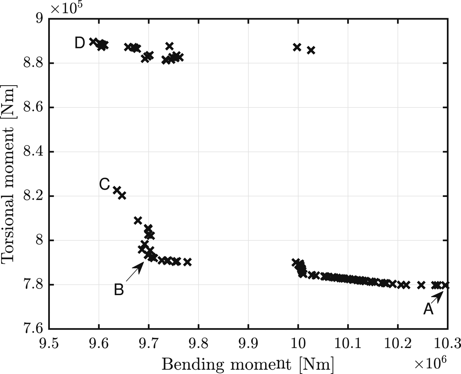
D. Optimal parameters: CM positions with flare angle fixed at 20°
The multi-objective optimization has been repeated for the coordinate of wingtip CM position as optimal parameters and assuming flare angle is fixed at 20°. The wingtip CM is constrained to lie in any position inside the wingtip. The results are reported as in previous cases. Figure 29 shows the Pareto front and Figures 29(b) to (d) show Figure 29(a) from different views. The results in Figure 29(b) show a corner representative of the optimal compromise between bending moment and torsional moment. Multi-objective optimization, optimization parameters: wingtip centre of mass position with a 20° flare angle.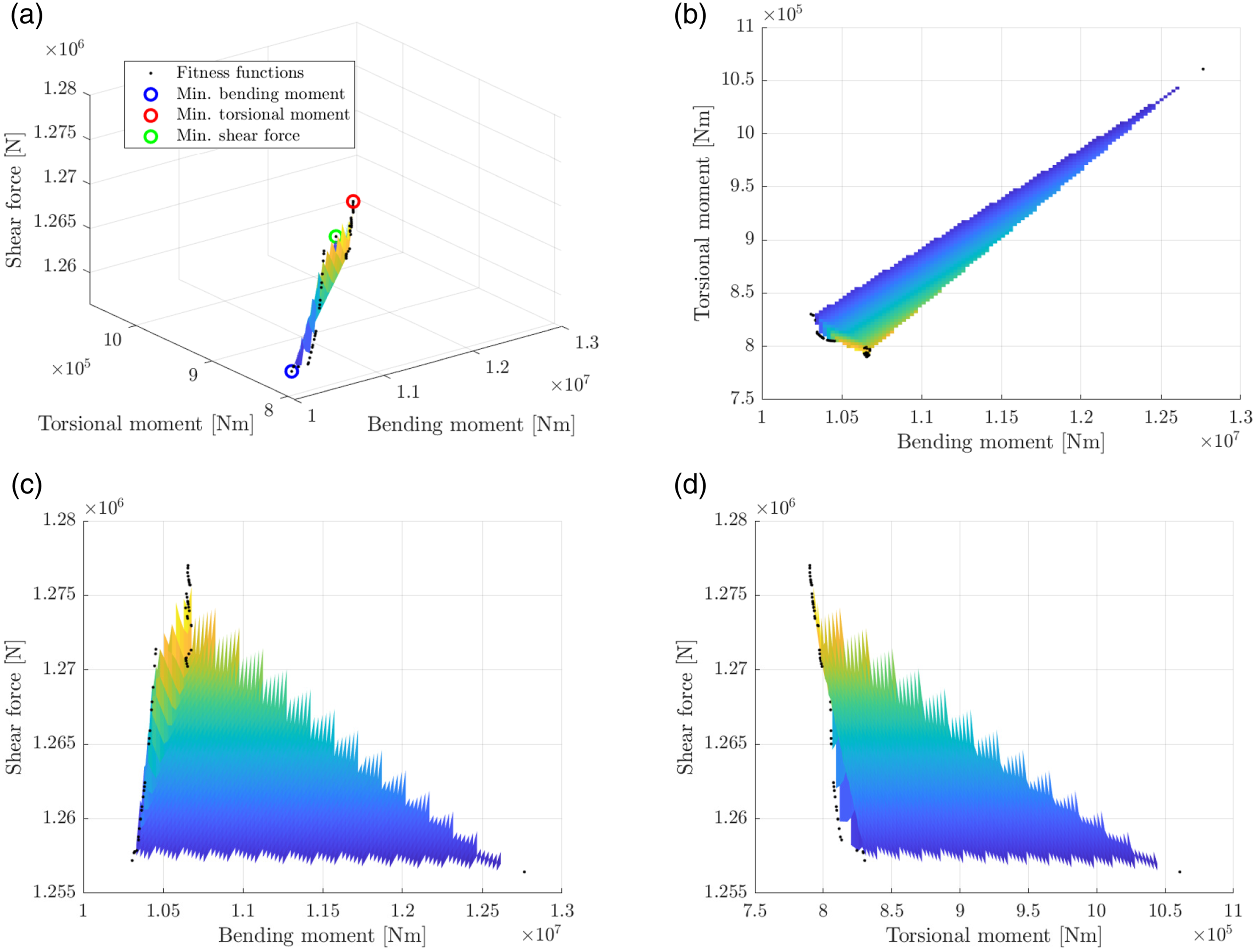
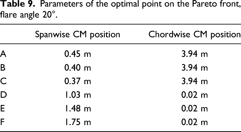
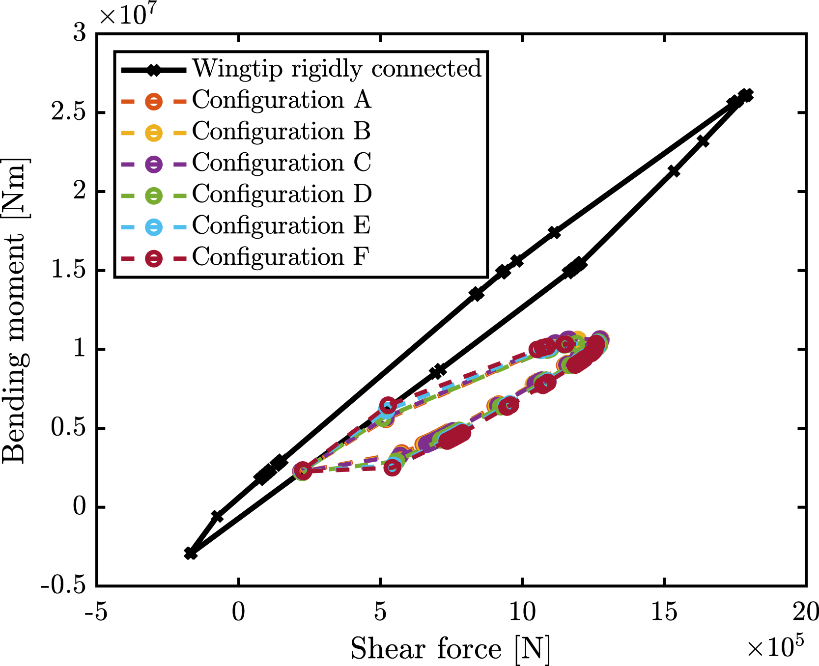
Figure 30 shows the fitness function points of Figure 29(b). In Figure 30, six fitness function values have been considered and the corresponding parameters are reported in Table 9. In the optimal configuration, the spanwise position of the CM is between 0.37 m and 1.75 m (corresponding to the 6% and 27% of the total wingtip span) and the chordwise position of the CM is 3.94 m for the first three configurations (corresponding to the profile trailing edge) and 0.02 m for the last three configurations (corresponding to the profile leading edge). Figures 31 and 32 show the convex hull in the case of wingtip rigidly connected and the optimized configurations tested on the whole flight envelope. As in the previous cases, the configurations selected can reduce all the quantities of interest with respect to the case of wingtip rigidly connected to the wing. The maximum peak of the bending moment is reduced by at least 59%, the maximum peak of the torsional moment is reduced by at least 35% and the maximum peak of the shear force is reduced by at least 29%. Pareto front on the bending moment and torsional moment plane at the optimal compromise, flare angle 20° Parameters of the optimal point on the Pareto front, flare angle 20°. Shear force-bending moment convex hull for the rigid connection and for optimized configurations. Shear force-torsional moment convex hull for the rigid connection and for optimized configurations.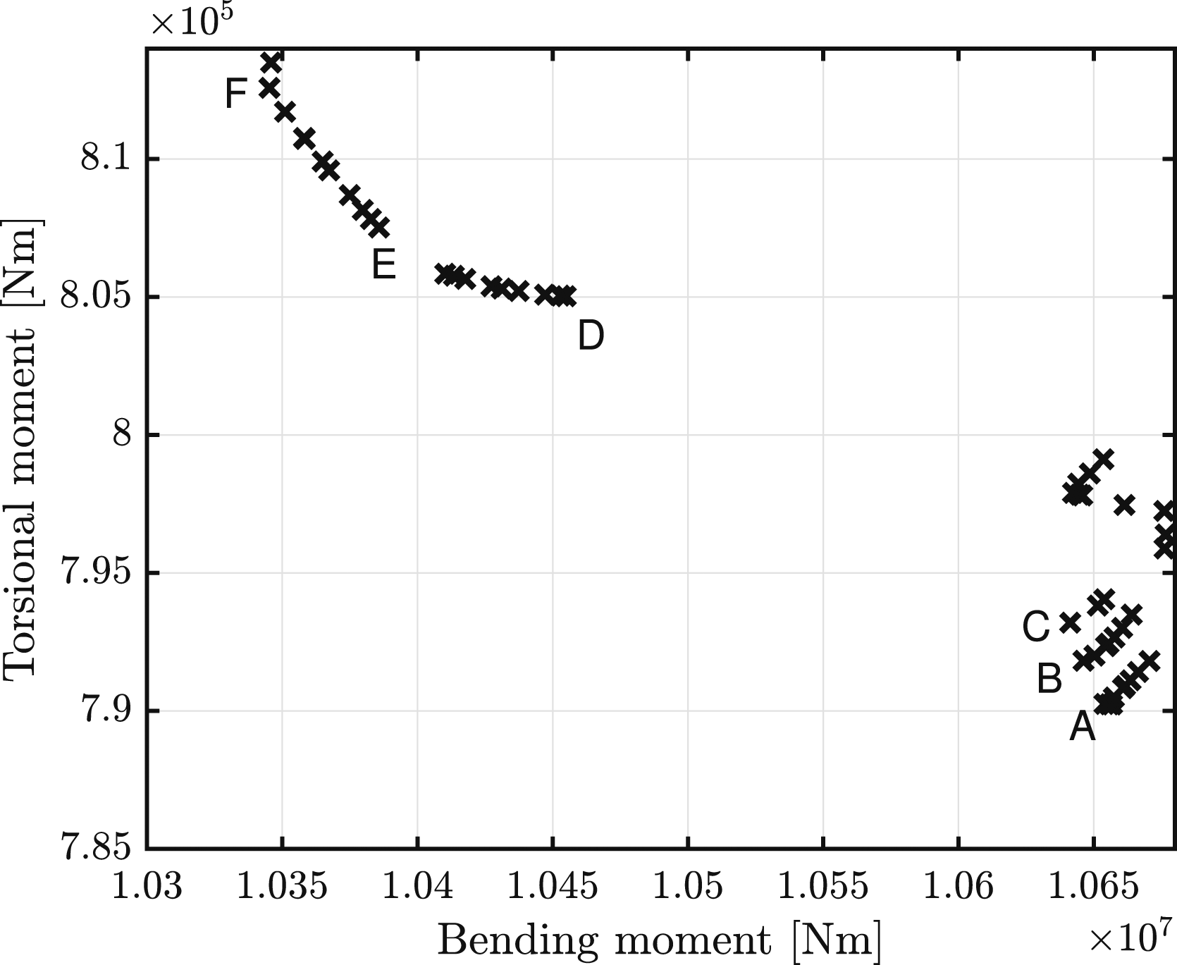
Flutter speed
After performing the optimizations, an important aspect is to ensure that the aircraft will never suffer aeroelastic instability. In the optimization process before calculating the gust response, an eigenvalue analysis is performed to verify the stability of the model. The regulation
22
required to ensure for each altitude is a minimum flutter speed greater than 115% of the maximum airspeed. It has been considered the optimal configuration of minimum bending moment (wingtip CM spanwise position 6.43 m and chordwise position 3.57 m) obtained in the section titled C. Optimal parameters: CM positions with flare angle fixed at 30°. Figure 33 shows the flutter speed for various altitudes. At low altitude, the flutter speed is lower than the limit. In the literature, there are different techniques to increase the flutter speed of a wing, such as changing the stiffness parameters or adding a balancing mass.3,19 This work has followed a different approach and considered the possibility to slightly change the parameters of the wingtip. In particular, it has been considered to change the flare angle or to introduce in the hinge connection an inerter, a damper or a spring. The results have shown that the introduction of the inerter and the damper are not able to increase the flutter speed but the introduction of a relatively small value of stiffness (k
θ
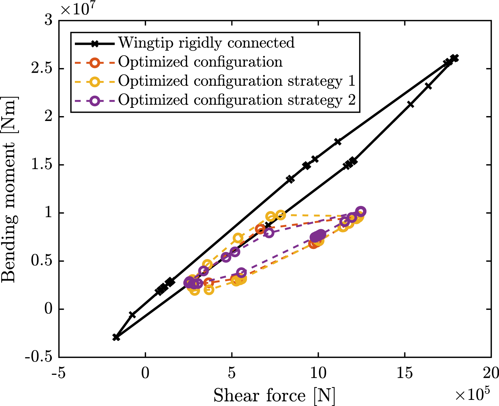
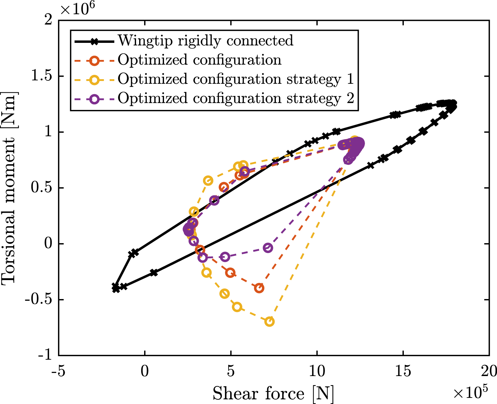
= 2.4 × 10⁵ Nm/rad) as well as the reduction of the flare angle (1.7% reduction) are able to increase the flutter speed as shown in Figure 33, without compromising the capability for gust load alleviation. Figures 34 and 35 show the convex hull of, respectively, the shear force and bending moment and the shear force and torsional moment for the reference configuration, for the optimized configuration, for the optimized configuration with the reduction of the flare angle (strategy 1) and for the optimized configuration with the introduction of the stiffness on the hinge (strategy 2). Flutter speed at different altitudes, in the reference configuration, in the optimized configuration, in the optimized configuration with smaller flare angle (strategy 1) and in the optimized configuration with stabilizing stiffness connection (strategy 2). Shear force-bending moment convex hull obtained in the reference configuration, in the optimized configuration, in the optimized configuration with smaller flare angle (strategy 1) and in the optimized configuration with stabilizing stiffness connection (strategy 2). Shear force-torsional moment convex hull obtained in the reference configuration, in the optimized configuration, in the optimized configuration with smaller flare angle (strategy 1) and in the optimized configuration with stabilizing stiffness connection (strategy 2).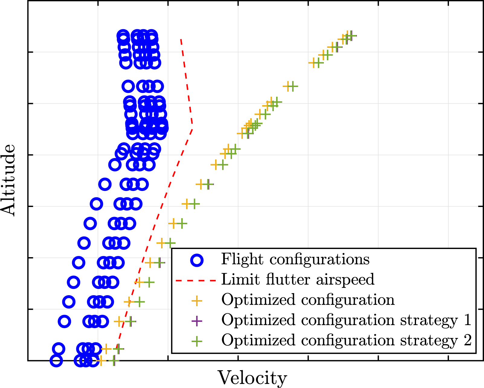
Conclusions
Two aeroelastic models representing a symmetric aircraft were developed. The first model consists of two rigid body modes and the torsional and bending modes of a straight wing. The second model was developed by including an additional degree of freedom due to wingtip rotation in the first model. The developed model was validated against an existing model’s gust responses in the literature for the case in which wingtip rigidly connected to the wing (high rotational stiffness value), and the results show good agreement. The gust response analysis considering different stiffness connections of the folding wing have shown that if the wingtip is free to rotate at the hinge it is possible to reduce the bending and torsional deflection and consequently reduce the moment transmitted from the wing to the fuselage.
The model considered the dimensions and weight distribution of a civil commercial aircraft. The gust response for the whole flight envelope was considered and in the frequency range prescribed by the airworthiness regulations. Different multi-objective optimizations have been performed to explore the possible combinations of the flare angle, wingtip span and position of the wingtip CM. The results show a wide range of suitable combinations, so when a detailed model is available, it is possible to select the most suitable configuration. The different possible solutions were shown to overcome the reduction in the flutter speed through the use of a spring in the connection between the wing and the wingtip and through the reduction of the flare angle. These solutions result in a small deterioration in the ability to relieve gust loads. The optimizations have shown that the choice of the wingtip span, the CM and the flare angle are interconnected. Moreover, the increase of the wingtip span or the flare angle can produce better gust load alleviation, and between these parameters, the wingtip span is the most sensitive parameter. To ensure the stability of the aircraft, the increment of the weight of the wingtip has to be linked to the change of the CM position.
Further investigations are needed in order to better understand the effect of the degrees of freedom not considered. Moreover, experimental tests will be necessary in order to validate the models.
Footnotes
Acknowledgements
The research leading to these results has received funding from the Engineering Physical Science Research Council (EPSRC) through a programme grant EP/R006768/1. Davide Balatti also acknowledges the PhD scholarship funded by the College of Engineering at Swansea University.
Declaration of Conflicting Interests
The author(s) declared no potential conflicts of interest with respect to the research, authorship, and/or publication of this article.
Funding
The author(s) disclosed receipt of the following financial support for the research, authorship, and/or publication of this article: This work was supported by Engineering and Physical Sciences Research Council (Grant no. EP/R006768/1).