
Abstract
This article introduces a novel mechanism exhibiting a two-stage, non-linear softening torsional stiffness designed to improve the aerodynamic performance of the Semi-Aeroelastic Hinged wingtip concept, while retaining its gust load alleviation capability. The device is comprised of simple mechanical components including gears, tendons, and springs, and is fully passive. Its kinematics are derived to analytically model its behaviour, establishing the two-stage stiffness behaviour: an initial stiffer region, followed by a secondary, more compliant region at higher deflection angles. The higher initial stiffness helps balance the steady aerodynamic loads on the wingtip, allowing for a more horizontal wingtip position during cruise, improving aerodynamic performance. During gusts, the lower stiffness mode allows for large wing tip rotations and alleviation of gust loads. A device is sized and designed for a notional UAV. The analytical model is validated against a prototype mechanism. Further studies explore the impact of the various design variables on performance. The model is shown to accurately predict the experimental response which is also shown to be tailorable for a chosen design point. In this way the basic mechanical viability of the concept is shown in preparation for future studies into its aerodynamic and loads transmission performance.
1. Introduction
High aspect ratio wings are typically favoured on modern commercial airliners owing to their reduction in induced drag, which enables lower fuel consumption and emissions. Environmental legislation and economic drivers have accelerated this trend, as seen in aircraft such as the Airbus A330neo exhibiting wings with an aspect ratio of almost 11. Furthermore, there is a significant body of ongoing research into even higher aspect ratios, facilitated by using novel structural and aeroelastic approaches. For example, the Subsonic Ultra-Green Aircraft Research (SUGAR) concept proposed by Boeing included the Transonic Truss-Braced Wing (TTBW) aircraft configuration, which achieved an aspect ratio of 19.55 (Bradley et al., 2015; Droney et al., 2018) using an external bracing strut to allow such a high wingspan to be achieved without excessive wing root bending loads. Another high aspect ratio wing design is seen on the D8 design by MIT, Aurora Flight Sciences and Pratt and Whitney. This concept combines a wide lifting body ‘double-bubble’ fuselage with a rear engine installation and a ‘pi-tail’ empennage. With the integration of active aeroelastic tailoring technology, an aspect ratio of 15.4 is achieved whilst reducing both wing and fuel weight (Brooks and Smith, 2020; Drela, 2011). The EU-funded RHEA Programme explored ultra-high aspect ratio wing concepts, including one with two separate fuselages and a wing aspect ratio of 20.47. Analysis showed this configuration, which included Hybrid Laminar Flow Control and advanced composite technology, had the potential to reduce fuel consumption by up to 45% for long range missions (Ma and Elham, 2021; Ma et al., 2022, 2023).
During all phases of flight, aircraft are subject to unpredictable gusts and airflow perturbations. These can significantly increase the aerodynamic loading experienced on the wing and thus the resulting root bending moments– particularly challenging for higher aspect ratios. Worst case gust loads are often a critical design driver for the wing structure, as they can generate larger load factors than manoeuvre-induced loading (Guo et al., 2015). Designing high aspect ratio wings strong enough to sustain these loads can therefore lead to significant added mass, owing to the larger moment arm of the longer span and the cross-sectional design constraints of the relatively thinner and smaller chord wings. Research into solutions which can mitigate this design trade-off, ensuring that the improved aerodynamic performance of the higher aspect ratio isn’t undermined by the requisite mass increase is essential. As a source of inspiration, gust alleviation is well documented in natural flyers, for example barn owls have been observed to elevate their wings rapidly about the shoulder (Figure 1(a)) to dump excess lift in response to an oncoming gust, reducing translation of their torso (Cheney et al., 2020).
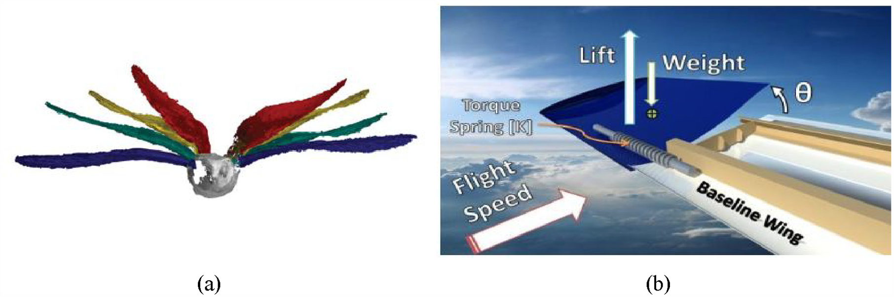
Gust load alleviation in nature and engineering, (a) three-dimensional reconstructions of a barn owl’s response to gust perturbations (Cheney et al., 2020) and (b) an example of a passive twist wingtip (Guo et al., 2015) concept for rejecting gusts.
Inspired in part by these gust alleviation strategies in natural fliers, there have been several design concepts proposed for gust load alleviation devices which allow for motion of the wing tips. Guo et al. (2015) introduced a design for ‘passive twist wingtips’, implementing wingtip rotation around a spanwise axis (Figure 1(b)). Although up to 21% reduction of wingtip deflection was measured during gust loads, the addition of this device led to a reduction in rolling moment generation, and an adverse impact on flutter characteristics; hence, a locking mechanism was suggested for future implementation.
In an alternate concept now known as the Semi Aeroelastic Hinge (SAH), a folding wingtip is added which is able to freely rotate upwards during gusts to dump excess lift (Castrichini et al., 2016). The hinge line of this wingtip is orientated outwards relative to the freestream flow, in what is known as a flare angle, on the order of 10°–15° (Figure 2(a)), which introduces a geometric coupling between rotation and wingtip pitch that progressively reduces the effective angle of attack of the wingtip as it rotates upwards, leading to reductions in lift and therefore root bending moment greater than those achievable due to wingtip flapping alone, which reduces lift by reorientating the wingtip lift vector away from vertical. The flare angle leads to the aerodynamic torque about the hinge having a change in magnitude opposite to the direction of motion (decreasing for upwards rotations, increasing with downwards rotations), and so it can also be thought of as a form of restoring aerodynamic stiffness. The SAH was shown to successfully reduce peak wing root bending moments in wind tunnel testing by up to 11% for a model with a 10° hinge flare angle (Cheung et al., 2020). Furthermore, owing to the flare angle, the wingtip was shown to have inherent static stability in terms of rotational torques about its hinge, although the impact of this additional degree of freedom on the wing and aircraft level dynamic aeroelastic response is complex and the subject of ongoing work.
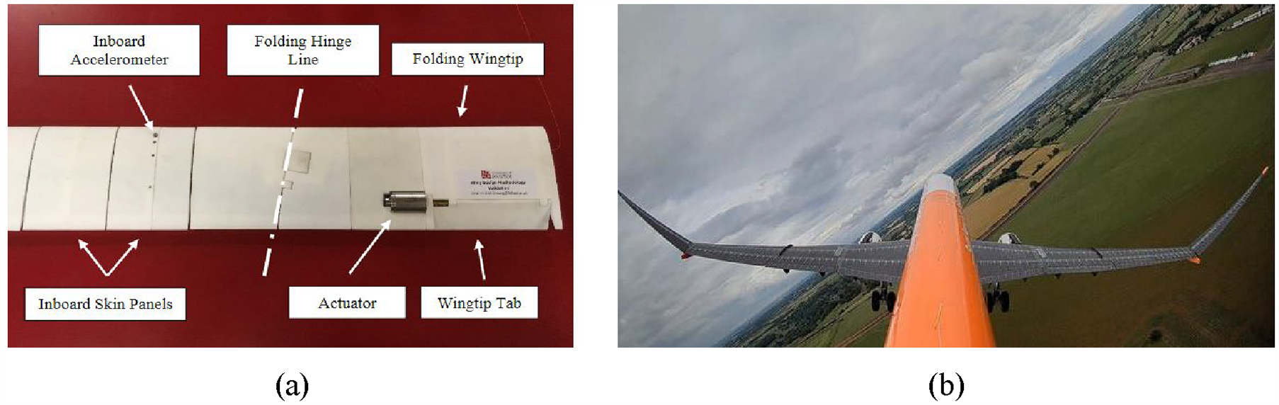
Semi aeroelastic hinge concept, (a) wing tunnel test model showing flared hinge line (Cheung et al., 2020), and (b) AlbatrossOne demonstrator in flight, wingtips unlocked (Airbus, 2020).
The SAH concept was flight tested at model scale in the Airbus AlbatrossOne (Wilson et al., 2022). In this 3.2 m span model aircraft, which first flew in 2019, the wing tips can freely rotate during flight, allowing for unactuated rotation in response to gusts (Airbus, 2020). From strain gauge measurements taken during flight at two different spanwise locations, it was clear that despite a fairly high experimental scatter owing to wind speed variation and turbulence, the freely rotating wing tips on average reduced bending moments on the order of 20%–30% and 40%–50% at 35% span and 56% span respectively (Airbus et al., 2019).
Such results show the promise of appropriately designed hinged wingtips to minimise wing root bending moments. However, in a freely rotating configuration the equilibrium steady state rotation angle of the wingtip will not be zero, instead being determined by the balancing of aerodynamic and mass moments about the hinge. This wingtip rotation will lead to some loss of lift due to inwards rotation of the local lift vector on the wingtip, and may add additional drag penalty depending on the design and configuration of the hinge itself (e.g. if there are any gaps in the wing surface required for rotation of the hinge). While the aerodynamic benefits of the higher aspect ratio should outweigh these effects with careful design, it may still be beneficial to seek approaches that allow the wingtip to fly at a more level orientation in normal operation without significantly impacting the ability of the tip to rotate in the event of a gust.
To this end, this work introduces a passive mechanical device that uses nonlinear, softening torsional stiffness to keep the wingtip more aligned with the rest of the wing in normal operation, but which softens as the wing rotates in order to minimise the transmission of moments across the hinge during gusts. This augmented hinge approach would thereby minimise the drag penalty imposed by the wingtip rotating in normal flight, whilst still providing the benefits of gust load alleviation on peak root bending moments, and therefore wing structural mass.
The mechanism proposed here is motivated by initial numerical studies exploring a theorised (but not designed) piecewise linear variable stiffness device for the SAH (Castrichini et al., 2015). This notional device had a very high initial stiffness which drops to virtually zero stiffness once a predefined threshold hinge moment is exceeded (in effect acting like a clutch). This was shown to significantly reduce dynamic loads when compared to a basic linear stiffness hinge spring.
Non-linear stiffness devices are also of interest in the field of robotics, particularly with regards to allowing for safe human-machine interaction. A range of different devices, both active and passive, based on various combinations of springs, pulleys, tendons, cams etc., have been proposed (Pervez and Ryu, 2008; Zacharaki et al., 2020). These devices demonstrate a high stiffness when the input force is below a certain threshold for high positioning accuracy, which rapidly falls to a lower stiffness for higher input forces such as in the event of a human-robot collision. Examples include the Safe Joint Mechanism (Park et al., 2009), noncircular pulley-spring mechanisms (Kim and Deshpande, 2014), Spring-Clutch torque limiters (Lee et al., 2009) and a Mechanism of Multiple Joint Stiffness (Medina et al., 2016).
We propose a simple device, different in design from previous work, that creates a softening, non-linear torsional stiffness based on a two-stage tendon wrapping principle and explore its application to the SAH concept. The kinematics of the device will first be derived, and its potential to tailor the torsional response of a hinged wingtip will be explored in the context of a notional medium-scale Unmanned Aerial Vehicle (UAV). This notional UAV is used only to size the initial spring stiffness of the device, more detailed consideration of the device on unsteady aerodynamics or transmitted loads is outside the scope of this initial mechanism concept focused paper. While such analysis is a very important part of considering the impact of this device on the performance of the SAH concept, it is useful to first demonstrate the basic operation of the concept and the high degree of tailorability in its response before undertaking aero-structural studies. To this end, an initial prototype is manufactured and experimentally characterised, showing both the intended functionality of the concept, and good agreement between predicted and measured torque profiles. Finally, the impact of the various design parameters on the resulting performance is explored in more detail, demonstrating a high degree of control over the stiffnesses, peak loads and wingtip angle at which the softening behaviour commences.
2. Operating principle
The basic operating principle of the proposed mechanism is shown in Figure 3, with the inboard wing and rotating wingtip being shown schematically as simple beams, with the device acting between them. It can be seen that rotation of the hinged wingtip drives rotation of a tendon mounting arm through a pair of spur gears, to allow for rotation amplification, rotating the tendon arm more than the wingtip (by a factor of 3:1 in this case). This tendon arm is then connected to a linear extension spring through an axially stiff tendon. This tendon would ideally be made from a light weight, wear resistant, high performance, fibre such as Ultra High Molecular Weight Polyethylene or aramid that has been braided or twisted into a cable/cordage form factor. This would provide a desirable combination of high axial stiffness and low bending stiffness.
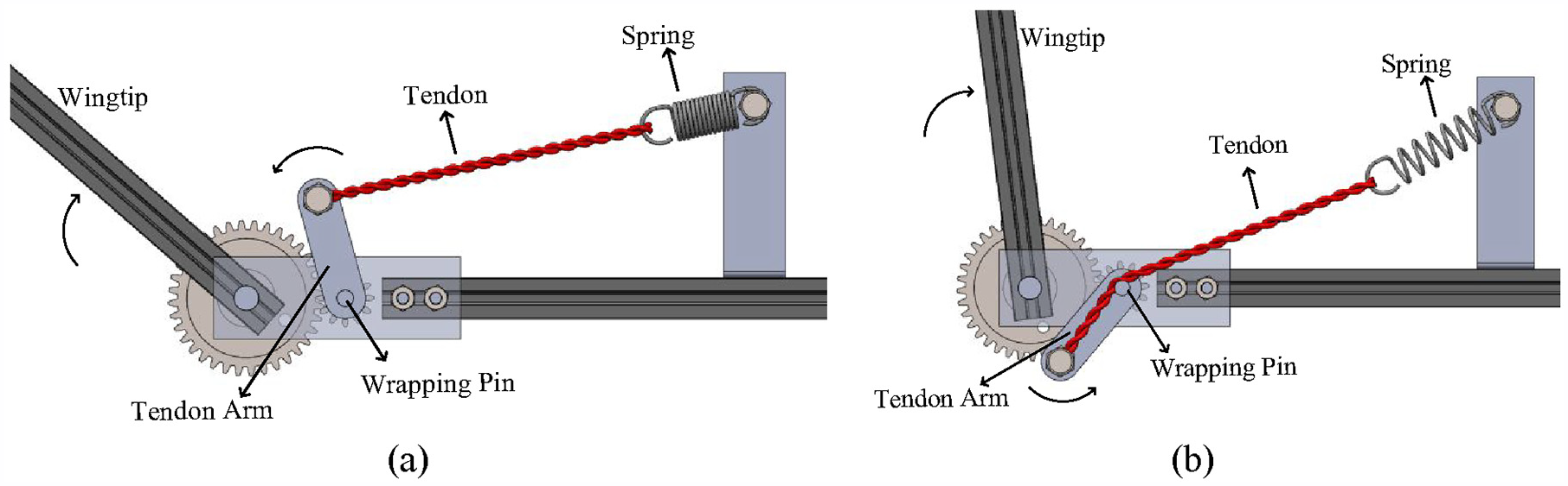
Schematics showing operation of the proposed non-linear torsional stiffness mechanism, (a) initial higher stiffness for smaller wingtip rotation angles (Region 1) and, (b) lower stiffness tendon wrapping stage at higher wingtip angles (Region 2).
The torsional stiffness this device adds to the wingtip rotation can be characterised into two distinct regions. In the first stiffness region (Figure 3(a)), referred to here as Region 1, upwards rotation of the wingtip creates a trigonometrically varying torque about the shaft the tendon arm is mounted on. This torque initially increases owing to the increase in moment arm at which the spring force acts relative to the shaft, combined with the increase in spring force as it is extended by the tendon, before reaching a peak torque. The torque then decreases trigonometrically as the moment arm decreases faster than the spring force increases. Region 2 begins when the tendon contacts an extension of the tendon arm shaft. The presence of this constant diameter shaft causes the bending compliant tendon to wrap around it, effectively acting as a pulley with a constant moment arm. In this region the constant moment arm and gradually increasing spring force leads to a low and nearly constant torsional stiffness. The other benefit of wrapping the tendon around a pin is that it is not able to cross over the rotation axis of the tendon arm, which could otherwise create an ‘over-centre’ effect that could induce a snap through, or bistable type behaviour that exhibits a negative stiffness response over a certain portion of the operating range. The fact that the tendon is not able to cross the rotation axis means that the torque generated by the device always act to restore the wingtip to its equilibrium position, and so it helps ensure the overall stability of the wingtip response.
Using this mechanism, the torsional stiffness seen by the wingtip can be varied significantly with rotation in a highly tailorable manner, with the specific response controlled via the choices of gear ratio, extension spring stiffness, and geometry of the tendon arm and spring mounting, as we will explore further below.
The mechanism is designed to operate within Region 1 during normal cruising flight, where the higher level of stiffness will help push the wingtip downwards, increasing lift generation and reducing drag at the design lift coefficient. Only under sufficiently large gusts will the wingtip rotation be high enough for the device to enter Region 2, at which point the significantly reduced torsional stiffness allows for alleviation of the gust load with minimal added torque (and therefore wing root bending moment) from the device itself. Note that even in Region 2 a small restoring torque is still generated, helping return the wingtip back to the cruise position once the gust has passed.
The intention of this initial concept introduction paper is to show the basic operation, viability and tailorability of the two-stage response of the device, and so we must first start by deriving the kinematics and torque response that result from a given selection of design variables, after which we can explore the impact of those design variables on performance to show that there is a very wide design space available in order to tailor the response to the design requirements (e.g. torsional stiffnesses, peak loads, wingtip angle at which Region 2 starts, etc.) of any particular SAH wingtip that might be considered in future studies.
3. Mechanical performance prediction
In order to predict and understand the performance of this mechanism, an analytical model of its quasi-static kinematics was derived and numerically implemented in MATLAB (MathWorks, USA). The kinematics were derived by considering the torque acting on the wingtip, as driven by the gearing, geometry of the tendon arm, and length and orientation of the tendon and spring force vector.
The intended operating range of the SAH includes both positive (upwards) and negative rotations, on the order of −20° to +90°, but this work will focus on positive rotations as these are of primary interest for normal cruising flight. Negative wingtip rotations may be experienced during landing or manoeuvring flight (e.g. rolling), and should be considered in more detail in future work. This mechanism concept in its basic embodiment will simply go slack during negative wingtip rotations, as the tendon arm’s rotation will in that case decrease the distance between the tendon and spring mounting points in a manner which causes the tendon (which cannot carry compressive loads) to become slack. This effectively means that the device has no impact on the torque balance of the wingtip during negative rotations, although from a design standpoint it would be important to ensure that the slackening cable would not be able to come unattached or get hung up on anything. Alternatively, the device could potentially be built with a bias rotation, such that it is active over the full angle rotation range, with the design tailored to provide appropriate torque levels, although this permutation of the concept will not be explored here. Generally speaking, the design parameters of the device can be tailored in response to specific operating ranges for any particular application, and so it is not essential to be overly specific on this point to begin with, and we will instead consider the design more generally.
In this work the kinematics and resulting torque profiles will all be considered from a quasi-static standpoint, with no consideration of the impact of dynamics. This is done primarily for simplicity in the context of this initial paper, but given that the response of the wingtip rotations and the corresponding variations in wing root bending moment are predominantly slower than 5 Hz (Castrichini et al., 2015), combined with the expectation that any complex or potentially undesirable dynamics of the device itself (e.g. there may be axial or out-of-plane vibrational modes of the tendon/spring component) will occur, or can be made to occur, at higher frequencies mean that it is reasonable to focus on the quasi-static performance to begin with.
Turning now to the geometry of this problem, the configuration of the mechanism is defined by the effective length of the tendon arm,
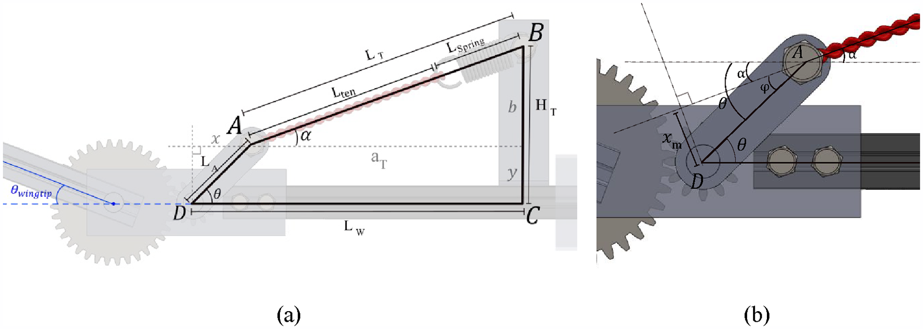
Geometry for Region 1 operation showing, (a) tendon arm and spring-tendon geometry and (b) tendon force moment arm.
The overall torque in the mechanism is driven by the relationship between θ, the length


3.1. Region 1 kinematics: Moment arm dominated
In order to assemble the overall torque equations for this concept, the spring length and effective moment arm of the tendon force must be found as a function of the tendon arm rotation angle for the two different operating regions. This is done first for Region 1.
3.1.1. Spring-tendon length,
Using Figure 4(a), the length of the spring-tendon pair

The lengths
3.1.2. Spring extension
The current length of the spring,

The spring extension,

3.1.3. Moment arm length,
The length of the moment arm,

The angle between the tendon and the horizontal is denoted α, hence φ and α can be related as follows


Where equation (9) is derived using Figure 4. Combining equations (7), (8) and (9) we find the length of the moment arm

Substitute equations (4) and (34) (Appendix A.1) into equation (10) to obtain:
Where equation (11) is expressed directly in terms of the key geometry design parameters.
3.2. Region 2 kinematics: Tendon wrapping dominated
At a design dependent contact angle,

Here,
Simplified geometry schematic for Region 2 kinematics with exaggerated pin radius, (a) point of initial contact between tendon and pin and, (b) tendon wrapping around pin.
There are multiple instances throughout the full range of motion where this occurs due to the trigonometry, hence an additional mathematical relationship was derived (Appendix A.2) and used to calculate the relevant value of
Since the tendon is wrapping around the pin as if it were a pulley, the length increment of the spring-tendon combination in this region,

Where
3.3. Combined force and torque model
Now that the behaviour in Regions 1 and 2 have been determined, the corresponding equations can be combined to produce spring-tendon lengths, forces and torques over the full range of tendon arm rotation.
The force in the tendon throughout the arm’s range of motion is found using Hooke’s law (equation (1)).
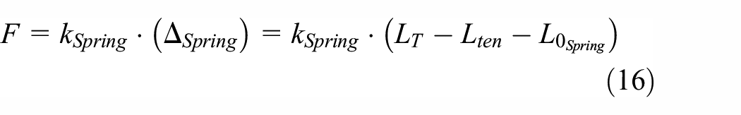
Where

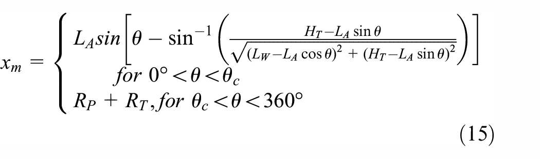
Combining tendon force F (equation (16)) and

Factoring in the applied gear ratio, u, the torque applied to the wingtip is found using equation (19):

3.4. Representative torque response
While the kinematics and torque model derived here will be validated against experimental results later in the article, it is useful to now consider a representative example of the torque evolution predicted, in order to show the basic operation of the device. This is done in Figure 6, where the two distinct regions of response can clearly be seen, with a trigonometrically varying response with high initial stiffness (denoted a
Example of torque response showing two distinct regions before and after contact between the tendon and tendon arm shaft. The design parameters for this example are:
As a further note, because the impact of friction on the operation of this mechanism is not modelled in the current work, the device would trace back through the same predicted torque profile as it returns to the normal equilibrium wingtip angle after a gust. As will be shown in the experiments, there is indeed friction present (especially in this first prototype), and so future work should look to include these effects into the model.
4. Case study: 3 m span UAV with hinged wingtips
In order to better understand the torsional behaviour of this new concept in a more specific design context, a representative device was sized for a nominal 3 m wingspan, 10 kg mass UAV using very basic assumptions. In line with previous work, the hinged wingtip is assumed to occupy the outboard 25% of the span. This scale of UAV is fairly common, and is, incidentally, also representative of an adult male Wandering Albatross (Pennycuick and Lighthill, 1982). The primary focus of this case study is to understand how much of reduction in torsional stiffness is achievable due to the two-stage behaviour of the concept given reasonable, albeit low fidelity, constraints on the first stage stiffness driven by aerodynamic performance assumptions and geometric limitations on the device itself, specifically its need to fit within the wing. To this end, we will first define the loads acting on the wingtip as a balance of aerodynamic and mass moments, before introducing an aerodynamic constraint on wingtip rotation which defines the required first stage stiffness. We then establish reasonable limits for the various geometric parameters and run a full factorial design parameter sweep in order to investigate the achieved reductions in stiffness during the second, gust alleviation stage of operation. Note that as the purpose of this case study is to just get a rough idea of the magnitude of stiffness that would be useful, the numbers chosen are intentionally quite notional and based on rough estimates.
4.1. Design scenario
We will design the device to achieve a certain Region 1 stiffness that allows for the wingtip to balance in normal cruising flight at a fairly low angle, which was chosen to be

In order to estimate the torque about the hinge generated by the distributed lift load on the wingtip, we can start by assuming each half of the wing generates a lift equal to one half of the weight of the 10 kg aircraft. If we then assume an elliptical lift distribution (equation (20)) and an undeflected wingtip, as shown in Figure 7, then we can solve for the value of b in the equation for an ellipse (given a equal to the semispan) that provides the required lift.

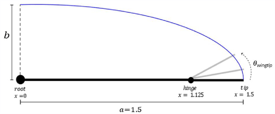
Diagram showing assumed elliptical lift distribution and wingtip hinge location.
Equation (21) gives the total lift L as an integral of this elliptical distribution:
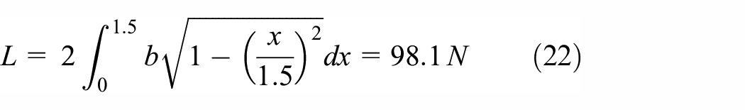
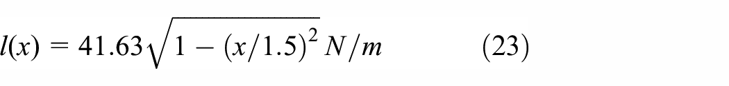
Solving for b gives a local lift at the root of
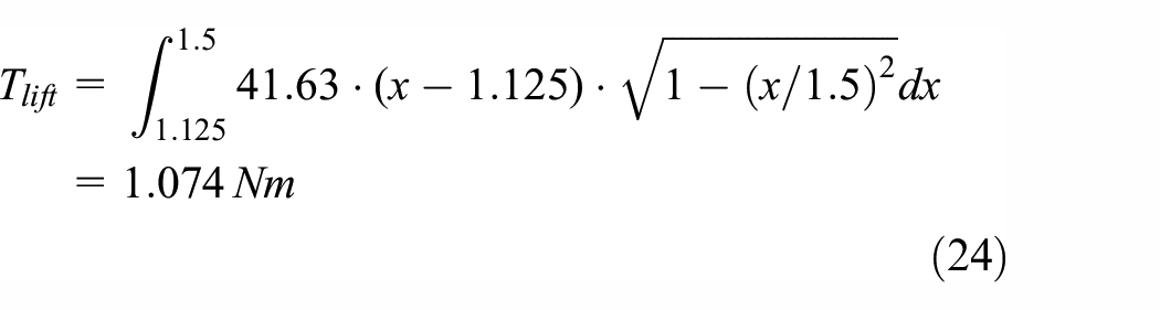
Given this lift distribution, we can now find the hinge torque generated by the lift acting on the wingtip as an integration along the wingtip of the local lift times its distance from the centre of the hinge as follows:
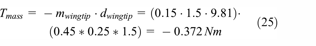
Partially countering the torque on the hinge generated by the lift will be some amount of torque generated by the integrated mass moment of the wingtip,
The torque that must be created by the device to maintain equilibrium can then be found:
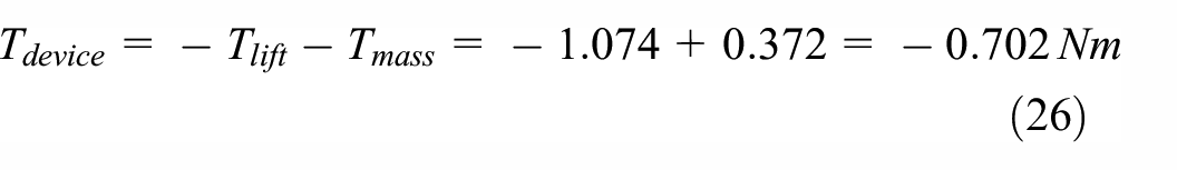
This device torque can be used to determine the torsional stiffness we desire for the first stage of device response by considering that this torque corresponds to a wingtip rotation of 20°. If we assume the device has been installed into the wing with the wingtip level, and ignoring the slight variation in lift and mass moment present at this fairly small wingtip rotation, then the first stage torsional stiffness
Hence, we require a hinge stiffness of approximately
4.2. Mechanism geometry exploration
Having established a target operational stiffness for the UAV case study, there are now two primary questions of interest: (1) can this level of stiffness be created by the device given practical constraints on its geometry (driven by the need to fit within the wing), and (2) how much of a reduction in stiffness can be achieved when the device switches to its second region of operation.
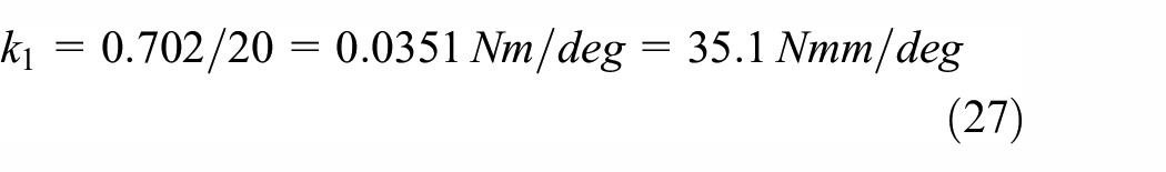
To answer these questions, we will first establish reasonable upper and lower bounds on the geometry before undertaking a design space exploration using a full-factorial design of experiments and the analysis approach derived above. Based on Table 1, 396 combinations were tested. After this we can consider the achievable performance in terms of Regions 1 and 2 stiffnesses.
Variable dimensions considered for case study.
Geometry limitations were considered by assuming a maximum aerofoil thickness of 40 mm for the 1.5 m long UAV wing. Consideration of component orientations within the wing combined with the need for additional space in the thickness direction for the structure of the wing led to the upper bounds for each design variable as listed in Table 1. The lower bounds were driven by the need to keep components large enough to avoid strength limitations and to keep the associated mounting brackets, bearings, torque transfer pins, etc. large enough to be readily made from commercially available components. The minimum spring mounting length also took into consideration the desire to be able to trial different commercially available springs. The numbers chosen are therefore approximate, but they will give a reasonable insight into what is likely to be achievable in a more detailed design exercise.
The gear ratio was fixed in this work to be 3:1, as appropriate sized commercially produced gears with this ratio were available. Gear ratio can of course be changed in general (and is explored numerically later in this article), but fixing this variable in particular was quite useful for the experimental work that follows. Similarly, the selection of the spring stiffness was driven by what was commercially available in the relevant size range. Initial analysis with a range of off-the-shelf linear extension springs led to the selection of four specific spring configurations for this initial parameter sweep which had linear stiffness values of 0.275, 0.36, 0.55 and 0.72 N/mm.
The resulting torsional stiffness produced by the mechanism will be considered in the manner previewed in Figure 6, with a linear fit to the initial response in Region 1 (

4.3. Achievable performance
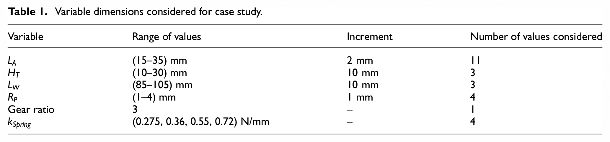
Results from the geometry exploration study are shown in Figure 8, where the stiffness ratio δ is plotted against the Region 1 stiffness
Example of parameter sweep results (for the cases with
If we now consider our design target for the case study,
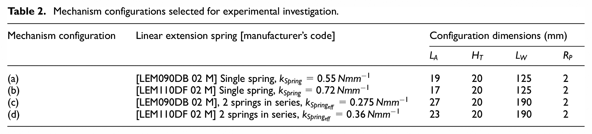
Four feasible configurations, one for each linear extension spring configuration, were selected for experimental verification in order to provide a more robust validation of the concept and analysis approach. The parameters for each of these configurations are shown in Table 2. These include two different extension springs used in both single spring and two springs in series configurations. This is done to show the adaptability of the mechanism design to different linear extension spring rates and configurations, as this particular aspect of the design has perhaps less design freedom than the continuously variable dimensions, particularly if off-the-shelf extension springs are to be used. Note that the springs used are sourced from Lee Spring, UK, with the manufacturer’s part numbers given in Table 2. Both
Mechanism configurations selected for experimental investigation.
5. Concept prototype and experimental characterisation
A prototype of the mechanism was designed, built, and experimentally tested in order to show the basic operation of the concept and to validate the developed analytical model of its torque versus rotation behaviour.
5.1. Prototype design and construction
Figure 9 shows the manufactured prototype mechanism, in an orientation roughly matching that of Figure 3 for consistency, with the wingtip to the left rotating about a shaft, with a 3:1 spur gear set connecting it to the tendon mounting arm, which in turn has the tendon and extension spring mounted to it. As this prototype is only intended to show the torque behaviour and not meant to be mounted inside of an actual wing, a simple, modular approach was used in its construction. This allowed for a single device to be modified for all four of the mechanism configurations tested. Slotted aluminium extrusions (10 mm × 10 mm in cross section) were used for the structure, while the mechanical components were made either from machined metal or 3D printed Polylactic Acid (PLA) plastic, depending on their functional requirements and load levels. The wingtip and tendon arm shafts were both 4 mm precision ground steel rod, mounted in miniature ball bearings to minimise friction. The tendon was made from 1 mm diameter braided Dyneema cordage, chosen for its high elastic modulus, low coefficient of friction, and high abrasion resistance (Dyneema®, 2023).
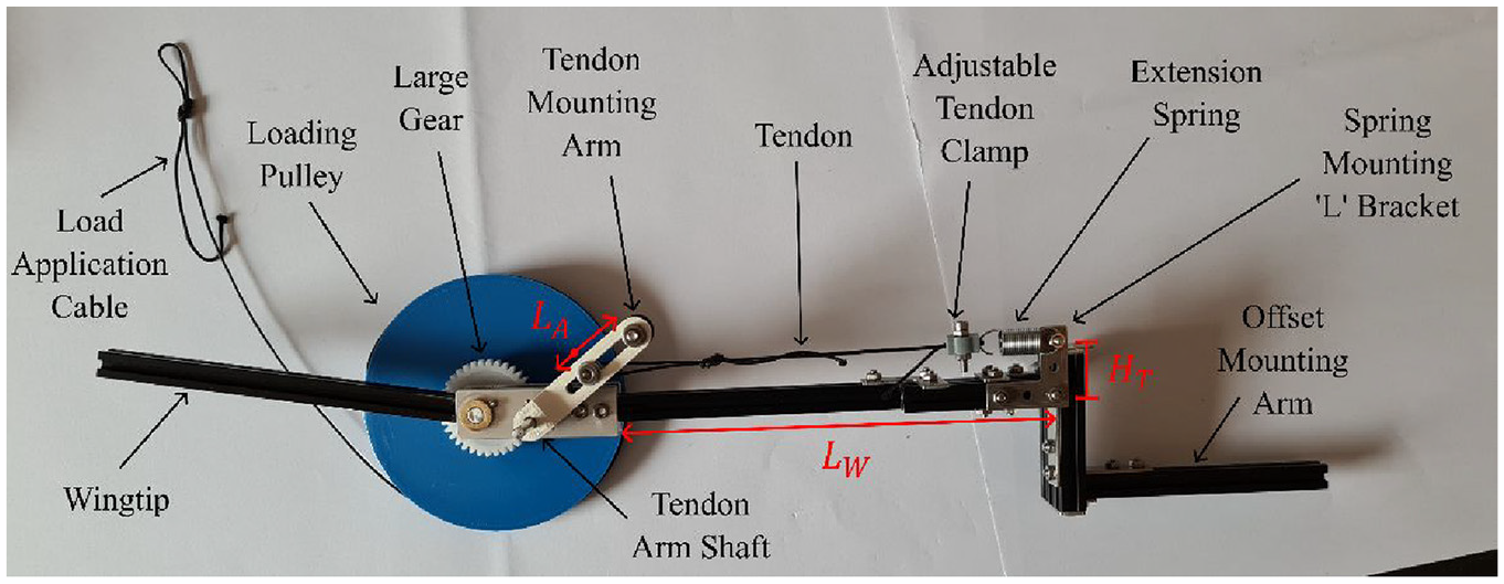
Prototype mechanism with labelled parameters.
The tendon arm was designed with a slot to allow for adjustment between the four different configurations. To allow the use of different extension springs, individually, and in series, the location of the spring mounting bracket is adjustable to allow
5.2. Mechanical testing methodology
To allow for testing of this torsional stiffness device on a universal testing machine (Shimadzu EZ-LX HS) which applies axial displacement, a simple linear-to-rotary motion conversion device was attached to the output (wingtip) shaft of the device. This consisted of a 3D printed, 50 mm radius loading pulley with a length of braided Dyneema® Ultra-High-Molecular-Weight Polyethylene (UHMWPE) loading tendon wrapped around and anchored to it, as shown in Figures 9 and 10. The other end of this loading tendon was then attached to the upper grip of the universal testing machine such that axial extension of the tendon induced rotation of the pulley and therefore the wingtip, with the tendon force measured by a Shimadzu 2 kN load cell (Part No. 346-55939-14) in the test machine then being converted to torque by multiplying by the constant radius of the loading pulley. This loading was displacement controlled with an actuation rate of
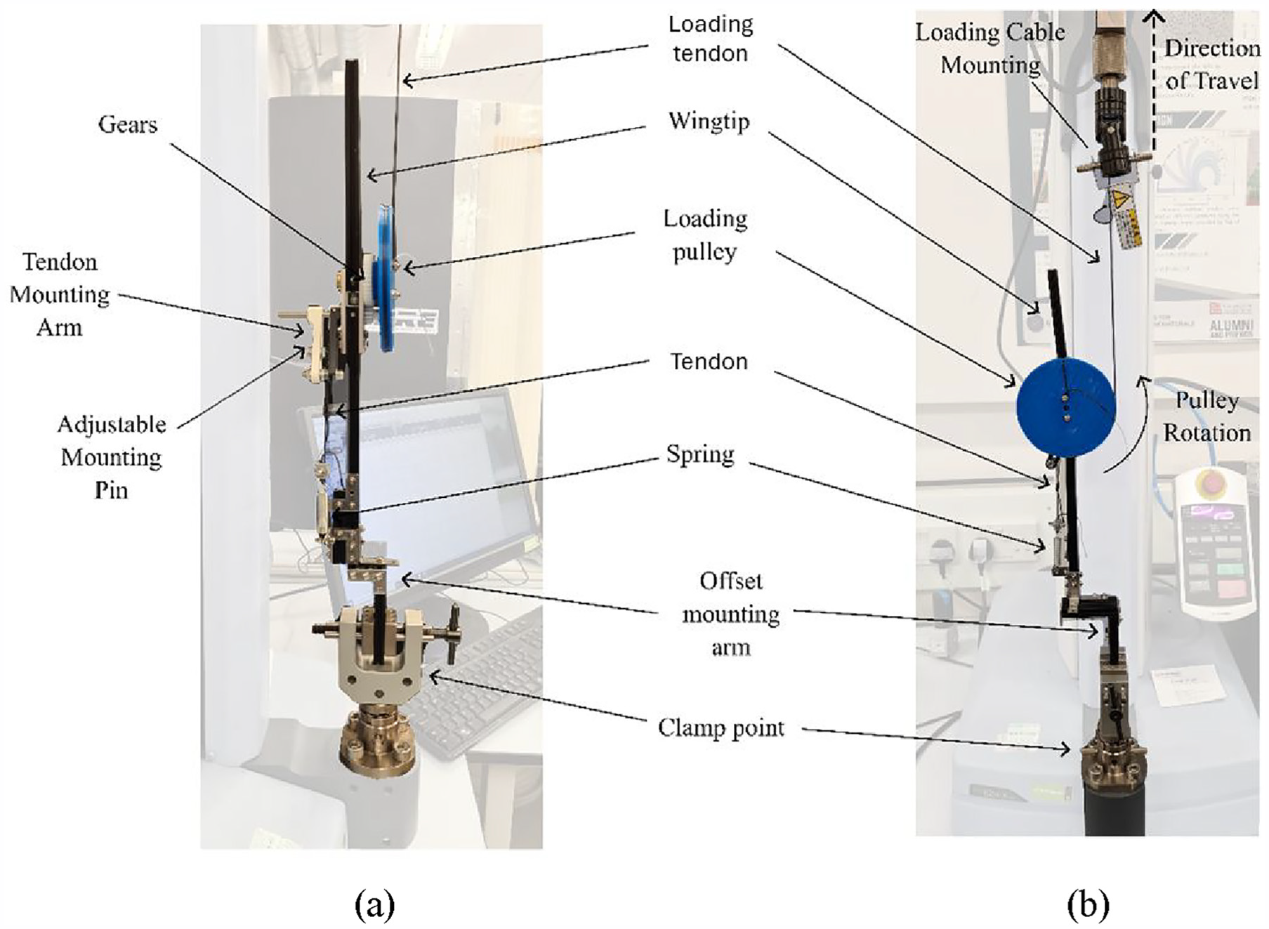
Experimental setup – mechanism supported vertically in a universal testing machine, (a) Side view and b) Front view.
5.3. Mechanism hysteresis
It was observed during initial testing that there was a modest amount of loading direction dependence in the measured torque values, indicating hysteresis, visible in the raw data shown in Figure 11. This is likely the result of friction within the mechanism and the loading pulley/cordage added for the experiments. This could include contact friction between the gears, friction caused by the wrapping/unwrapping of the tendon and loading cordage, rolling friction in the bearings used etc, which could at least in part be addressed in future prototypes through increased precision in the components and manufacturing. As the friction present in this prototype leads to an increase in measured torque during loading and a decrease in measured torque during unloading, it can be averaged out to provide a reasonable estimate of performance without friction, which is more appropriate for comparison against the developed model.
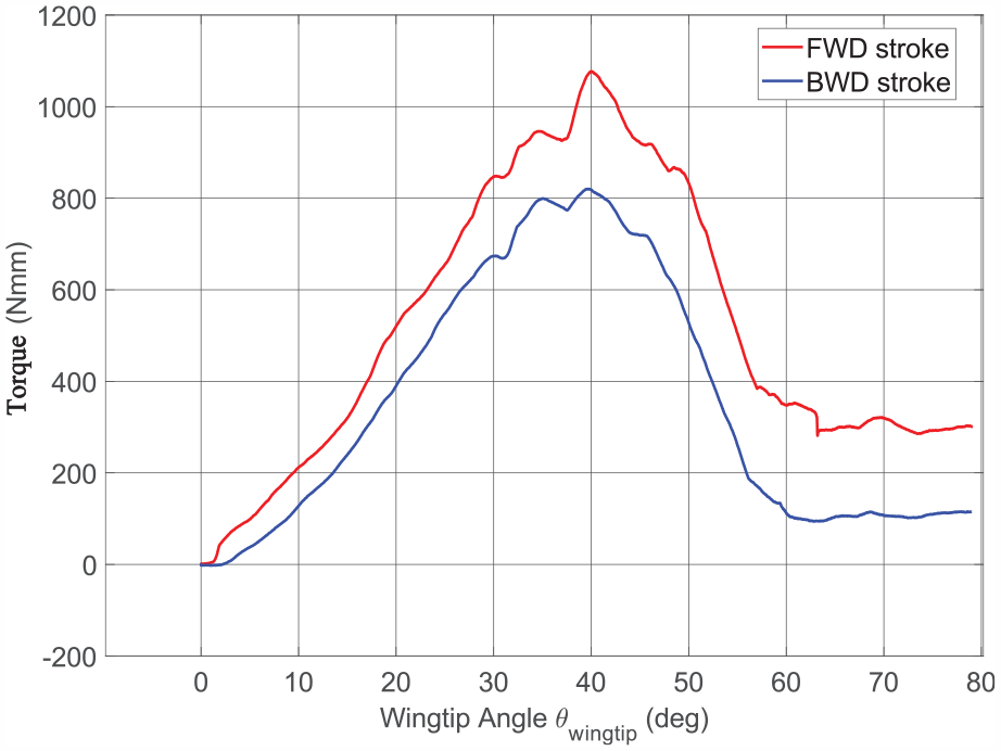
Torque versus rotation results showing the presence of hysteresis.
5.4. Torque versus rotation responses
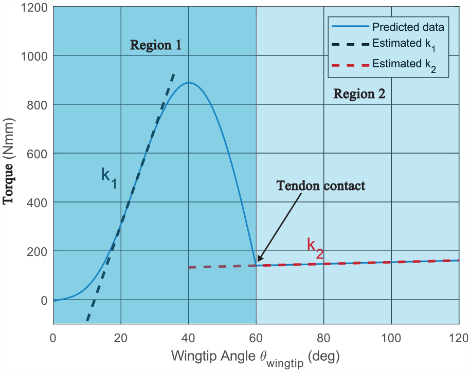
The torque versus output rotation results for the four different mechanism configurations are shown in Figure 12. Each configuration was cycled three separate times, and the results were averaged to produce the lines shown and the error bars, which show ±1 standard deviation. Note that while all of the recorded and averaged torque measurement points are shown, the error bars are plotted at larger intervals in order to keep the figure legible. The overall response is well predicted by the model, and clearly shows the two distinct regions of operation as intended. Linear regressions were fit to the response in Region 1, with an average error between measured and predicted gradients of −8.7% and a maximum error of −13%. Linear regressions of the experimental data were not taken for the Region 2 stiffness due to the limited angular range of data in this region and the reasonably high level of variability seen in the torque values. Despite this, it is still clear form the results that the Region 2 behaviour is well predicted by the model.
Wingtip torque versus rotation predictions and experimental data with estimated gradients. Error bars show
The reductions in stiffness between Regions 1 and 2 for configurations (a)–(d) are 98.4%, 98.1%, 99.2% and 99%, respectively.
Interestingly, the higher order torque variation seen in the experimental results (which is not predicted by the model) was highly repeatable across the three tests for each configuration, as shown by the tight error bars, although there is some configuration dependent variance in this with configuration (b) showing the highest variation. It is hypothesised that this variation is due to either the interaction between the loading tendon and pulley, which being 3D printed did not have a particularly smooth interface, the meshing of the gears, or a perhaps a combination of both.
The overall differences between the model and experiment are likely also affected by the need to take up the slack in the tendon and loading cordage, which introduces a small amount of uncertainty in initial displacement/rotation that would shift the curves laterally. There were also limitations in the accuracy with which
Overall, there is very good agreement between the experimental data sets and the model despite the simplicity of the analysis used. This model therefore provides a very useful level of fidelity and accuracy for exploring the use of this non-linear torsional stiffness device within hinged wingtips, or indeed anywhere else where its ability to provide high stiffness in a normal working range but minimal stiffness beyond that is useful.
6. Further design insights
Having established the basic viability of the operating principle behind this concept, it is useful to explore in more detail certain relationships that exist between the various design parameters and the resulting stiffness profiles to allow for deeper insight into the operation and scaling of this mechanism.
We first consider the impact of varying the two ‘moment arms’ which drive the transformation of spring force into torque in the two different regions of operation, namely the tendon arm length
An example of the impact of tendon arm length and pin radius on stiffness performance, with marker type indicating pin radius and marker colour indicating tendon arm length.
The pin radius
6.1. Single parameter variations
Another useful approach to understanding the impact of the geometry design variables on the achieved stiffness performance is to consider the impact of varying one parameter at a time on a single fixed baseline configuration. This can be done to show both the magnitude of variance in the stiffness and the shape of this variance, which is useful for understanding the underlying balance of forces and moments that drive this device. This is done for each of the geometry variables (
Effect on δ and
Considering Figure 14(a), we see that increasing
Increasing the vertical spring mounting offset
Similarly, for
In the final sub-figure, Figure 14(d), we can see again in another way that
6.2. Effects of varying gear ratio and spring stiffness
Finally, we can consider the impact of variations in the other two design parameters, gear ratio and spring stiffness, which aren’t directly part of the tendon arm rotation/tendon wrapping kinematics but instead effectively act to stretch and scale the overall response. This can be clearly seen by considering the torque versus rotation profiles in Figure 15.
Effect of varying (a) gear ratio and (b) spring stiffness on mechanism behaviour.
From Figure 15(a) it can be seen that the gear ratio acts to tradeoff torque for rotation. Increasing gear ratio leads to more rotation of the tendon arm for a given rotation of the wingtip, effectively compressing the response horizontally while also increasing the magnitude of the torque available, and the corresponding torsional stiffness in both Regions 1 and 2. This design variable is therefore particularly useful for tailoring the wingtip angle at which the device switches to its lower stiffness state, directly controlling the onset of the gust alleviation functionality. It may be useful in practice to first set the gear ratio, and to then use the other design parameters to modify the Regions 1 and 2 stiffnesses and peak torque value. Figure 15(b) shows the response with changing stiffness values for the linear extension spring, which effectively creates a direct scaling of the torque values at every rotation, which is very useful from a design standpoint for controlling the overall stiffness of the mechanism.
By changing gear ratio and spring stiffness together, and in further light of the single parameter variations shown earlier, it can be seen that there is considerable design freedom afforded by this concept that will allow for designers to have control over all aspects of the torque response, including initial stiffness, peak torque, tendon contact point, and second stage stiffness in order to ensure that the device, when integrated into a SAH wingtip, can be optimised based on its impact on the actual transmitted root bending moments which arise from critical gust cases. As mentioned earlier, this level of unsteady aeroelastic analysis is beyond the scope of this initial concept introduction paper, but the analytical model developed here can be used directly in future studies to predict the performance of this concept. It’s low computational cost and modest number of design variables makes it highly suitable for use within optimisation routines.
7. Conclusions
In this work a novel, non-linear, torsional stiffness device for use with hinged aircraft wingtips such as the Semi Aeroelastic Hinge concept was introduced. The device operates through a two-stage mechanism, utilizing in one stage a moment arm, and in another the interaction between a tendon and a wrapping pin, achieving a dramatic stiffness reduction of up to 99% at larger rotation angles. This is intended to add torsional stiffness to the normal working range of a hinged wingtip to balance the aerodynamic loads in order to achieve a more level wingtip orientation, increasing lift and reducing drag. During gust events however, the larger induced wingtip rotations push the device into its second operating stage, where the significantly reduced torsional stiffness allows for gust alleviation and reduction of wing root bending moments. This two-stage passive stiffness switching behaviour is accomplished with simple mechanical elements through tailorable contact between a tendon mounted to a rotating arm and a wrapping pin, creating a trigonometrically driven initial stage and a low stiffness pulley wrapping second stage.
In this article, the concept was introduced and its operating principle described. An analytical model of its operation was created through derivation of the kinematics and torsional response for the two operating regions. This model was then used to design a device for a nominal 10 kg UAV application. A prototype was constructed and mechanically tested, showing both the desired two-stage behaviour and a good level of agreement with the analytical model. It was also shown that a desired value of initial operating stiffness can be achieved with multiple different combinations of design parameters and spring stiffnesses, enabling the mechanism to be sized for implementation within aerofoils of various thicknesses. Further analytical studies then explored the impact of the various design variables on performance, highlighting the high level of tailorability inherent in the concept. This work has shown the basic operation and viability of the novel proposed concept. Future work will explore its application to a wing in more detail, including the use of wind tunnel testing, and, critically, numerical evaluation of its ability to reduce transmitted root bending moments under gust conditions.
Footnotes
Appendix
Declaration of conflicting interests
The authors declared no potential conflicts of interest with respect to the research, authorship, and/or publication of this article.
Funding
The authors disclosed receipt of the following financial support for the research, authorship, and/or publication of this article: This research was supported in part by the UK’s Engineering and Physical Sciences Research Council through Dr. Woods’s Early Career Fellowship: Adaptive Aerostructures for Power and Transportation Sustainability (AdAPTS), grant No. EP/T008083/1.
Data availability statement
Data sharing not applicable to this article as no datasets were generated or analysed during the current study.