
Abstract
The paper discusses optimality constellations for the design of boundary layer ingesting propulsive fuselage concept aircraft under special consideration of different fuselage fan power train options. Therefore, a rigorous methodical approach for the evaluation of the power saving potentials of propulsive fuselage concept aircraft configurations is provided. Analytical formulation for the power-saving coefficient metric is introduced, and, the classic Breguet–Coffin range equation is extended for the analytical assessment of boundary layer ingesting aircraft fuel burn. The analytical formulation is applied to the identification of optimum propulsive fuselage concept power savings together with computational fluid dynamics numerical results of refined and optimised 2D aero-shapings of the bare propulsive fuselage concept configuration, i.e. fuselage body including the aft–fuselage boundary layer ingesting propulsive device, obtained during the European Union-funded DisPURSAL and CENTRELINE projects. A common heuristic for the boundary layer ingesting efficiency factor is derived from the best aero-shaping cases of both projects. Based thereon, propulsive fuselage concept aircraft design optimality is parametrically analysed against variations in fuselage fan power train efficiency, systems weight impact and fuselage-to-overall aircraft drag ratio in cruise. Optimum power split ratios between the fuselage fan and the underwing main fans are identified. The paper introduces and discusses all assumptions necessary in order to apply the presented evaluation approach. This includes an in-depth explanation of the adopted system efficiency definitions and drag/thrust bookkeeping standards.
Keywords
Introduction
Novel propulsion systems and their synergistic integration with the airframe are expected to play a key role in pursuing aviation’s challenging long-term sustainability targets. The recuperation of aircraft skin friction-induced flow momentum via Boundary Layer Ingesting (BLI) propulsion – the so-called wake-filling propulsion integration – is considered to be a technological enabler for strong improvements in overall vehicular propulsive efficiency. Long known from the field of marine propulsion, the positive effect of wake-filling on propulsive power requirements has been subject to theoretical treatise in aeronautics over several decades (e.g. Smith and Roberts, 1 Goldschmied, 2 Smith 3 and Drela 4 ).
The most promising airframe component for wake-filling propulsion integration is the fuselage due to its large share of aircraft overall viscous drag. Initial experimental studies related to fuselage BLI and wake-filling were conducted for the boundary layer controlled airship body concept proposed by F.R. Goldschmied in 1957. 5 More recently, low-speed wind tunnel experiments were performed on a generic streamline body by ONERA 6 and TU Delft. 7 First experiments have also been performed at MIT for the D8 configuration. 8
The most straightforward way of tapping the full fuselage wake-filling potential (360° installation) can be realised through a single BLI propulsor encirculating the fuselage aft body in addition to the underwing main engines, also known as propulsive fuselage concept (PFC). 9 While a first patent with explicit reference to fuselage wake-filling propulsion integration had already been filed in 1941, 10 various concepts on how to exploit the postulated benefits of fuselage wake-filling have been proposed in the most recent past. Proposed PFC aircraft configurations include NASA’s ‘FuseFan’ concept, 11 the EADS/AGI ‘VoltAir’, 12 the Boeing ‘SUGAR Freeze’ 13 and the NASA ‘STARC-ABL’. 14 Within the EU-FP7 project ‘DisPURSAL’, 15 a first multidisciplinary design study of PFC systems layout for large transport category aircraft was performed. During the ongoing EU-H2020 project ‘CENTRELINE’, the PFC proof-of-concept and initial experimental validation is pursued. 16
Defining a PFC aircraft requires the best and balanced specification of a number of new top-level design parameters from the outset. Beside main design descriptors for size and positioning of the aft–fuselage BLI fan one of the most decisive design drivers is the fan power split between the non-BLI main engines and the BLI aft–fuselage propulsor. The purpose of the present paper is to provide guidance on the optimum choice of this key design parameter. Its optimal selection strongly depends on key system configurational and technological design decisions. Assuming an optimised aero-shaping, key influences are being exerted by the characteristics of the fuselage fan (FF) power train, i.e. the transmission efficiency and its specific weight, the performance of the main engines, as well as the aircraft application case, e.g. long range versus short range, and the overall systems design integration. Special consideration in the present paper will be paid to the impact of different FF power train options with regard to optimal power saving constellations for PFC aircraft design.
The effect of transmission efficiency on optimum PFC has been firstly evaluated by Gray and Martins 17 for NASA’s STARC-ABL in a numerical optimisation study based on 2D axisymmetric computational fluid dynamics (CFD) simulation results. Their results showed that increasing efficiency of the FF power train has a significant effect on the optimum configuration: for an increased transmission efficiency the maximum achievable PSC increases and the optimum design moves to higher FF power shares.
The present paper introduces an analytical formulation approach to the evaluation of PFC power savings that allows for parametric analyses on optimum design trends for maximum power savings including aero-propulsive as well as basic system weights effects. As an aerodynamic basis, design and analysis results from the CENTRELINE and DisPURSAL projects are employed. In both projects, preliminary CFD simulation-based PFC aero-shaping and power train conceptual evaluation have been performed for a wide-body aircraft application scenario featuring a standard payload capacity of 340 passengers. The PFC aircraft configurations in both cases feature two underwing podded power plants supplemented by an aft–fuselage BLI fan. While in DisPURSAL an independent third gas turbine engine powered the FF, the CENTRELINE FF is powered through turbo-electric offtakes from the wing-mounted main engines. An electric FF drive alleviates many problems associated with the aero-structural integration of mechanically powered FFs.
Methodology
In the present paper, the cruise power-saving potentials of PFC aero-designs developed during DisPURSAL as well as preliminary design solutions from CENTRELINE are analysed and discussed with regard to optimality conditions. The basic PFC aircraft configuration considered features three propulsive devices – two conventional under wing podded power plants and an aft-fuselage BLI fan. The studied PFC designs cover broad ranges of key design parameters such as FF size, longitudinal positioning and design pressure ratio, as well as, the split between FF and overall fan shaft power. In this section, the methodological foundation for the analytical treatment is presented. All presented formulation focuses on high-speed steady level flight conditions, in the first instance.
System definition and bookkeeping of aerodynamic forces
Aerodynamic forces bookkeeping
In order to meaningfully compare the aerodynamic performance of wake-filling and conventional non-BLI aircraft, unified definition rules for the aerodynamic forces are required. Therefore, it is helpful in the first instance, to differentiate between those aircraft components immediately affected by BLI propulsion system integration and those with slightly less intensive aerodynamic coupling to the BLI propulsion system. In case of a PFC aircraft, the fuselage and the FF propulsion system are particularly tightly coupled. This bare PFC configuration can be distinguished from the adjacent aircraft components such as the wing, wing-podded engines and the empennage, provided aerodynamic interference is tracked appropriately.
The aerodynamic forces acting on the bare PFC configuration are defined according to the momentum conservation-based control volume approach proposed by Habermann et al.
18
The net propulsive force NPFPFC,bare is the total effective net force acting on the bare PFC configuration without interference from the residual aircraft components. It is defined as the difference between FF disc force Fdisc,FF and the sum of integrated viscous and pressure forces on the component surfaces FPFC,bare

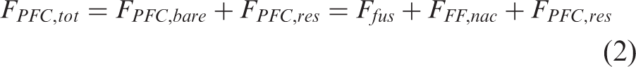
Specifically, FPFC,bare comprises the FF nacelle and fuselage aerodynamic forces. In contrast to FPFC,bare, the force acting on the overall aircraft FPFC,tot includes all aerodynamic forces acting on the components of the entire aircraft in clean configuration

As indicated in Figure 1, the rearward acting surface forces pointing in drag direction (Fwing, Fnac, Femp, Ffus, Fpyl, FFF,nac) have a positive sign. Thrust forces (Fdisc,FF, FN,main, NPFPFC,bare) are positive in accordance with MIDAP Study Group convention.
19
Bottom view of PFC aircraft with cruise aerodynamically acting force annotated and bare PFC configuration highlighted in blue.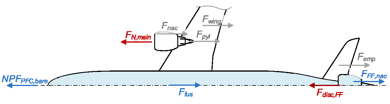
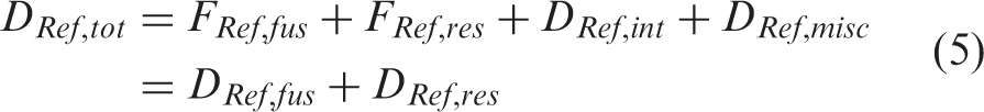
The overall aircraft drag DPFC,tot is the sum of the forces acting on the components, the possible interference drag e.g. between the bare PFC and adjacent airframe components Dint, as well as Dmisc. The miscellaneous drag term includes drag due to protuberances and leakages, as well as the potential flow buoyancy terms of the individual components, which in sum become zero for the closed aircraft body

The interference drag includes drag due to interference of all aircraft components, including interference at the wing–fuselage junction as well as the intersection of fuselage, vertical tail plane, and FF nacelle in front of and inside the FF inlet. A more detailed discussion of this is presented in the Baseline parametric settings section.
For a non-BLI reference aircraft, the total drag is defined analogously with
Main engine efficiency figures:
Definition of power plant overall efficiency: For fuel-powered aircraft, power plant overall efficiency is defined by the ratio of effective propulsive power Pthrust to the power supplied to the combustion chamber via fuel enthalpy flow Psupply (cf. e.g. Seitz et al.
20
)


The propulsive efficiency ηpr captures the dissipative losses in the flow field of the propulsive jet. For ducted propulsive devices this means the ratio of Pthrust and the power in the jet at the nozzle exit Pjet.
a
The core efficiency ηco in a gas turbine engine accounts for the high pressure (HP) system including upstream effects of the core mass flow, such as the inner streamtube, intake and ducting losses, as well as, polytropic compression in the fan and low pressure compressor. ηco describes the ratio between the ideal power Pco,id at the core engine exit plane CE that is available for the low-pressure turbine (LPT) to drive the outer fan, i.e. the part of the fan working on the bypass mass flow, and, Psupply. It can be expressed as (cf. Kurzke
21
) Control volume definition for podded power plant system installation including thermodynamic station designation.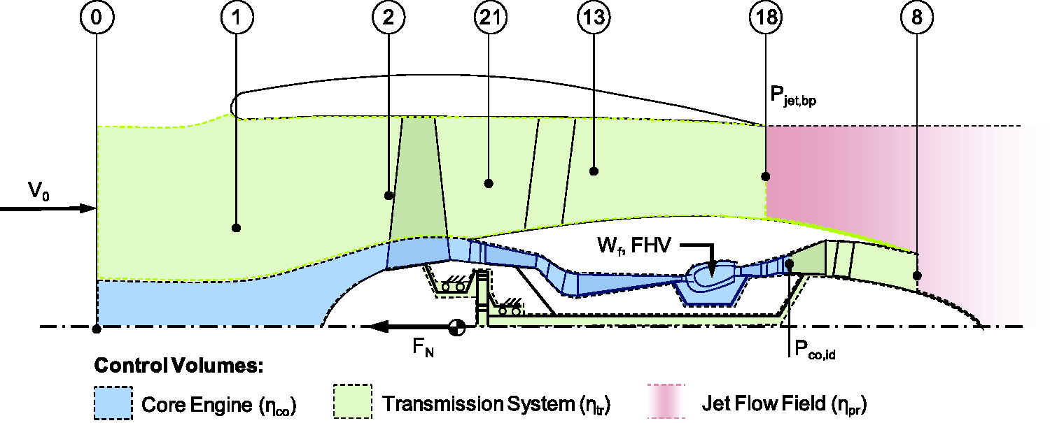

Aero-numerical analysis and shape optimisation approach
The aerodynamic data basis of the present analysis is formed by 2D-axisymmetric Reynolds Averaged Navier Stokes (RANS) CFD simulation results of the bare PFC configuration, i.e. the simplified fuselage body including the aft–fuselage propulsion system for typical cruise conditions at zero angle of attack. Simulations within DisPURSAL were performed on multi-block structured meshes with ONERA's CFD software ‘elsA’ 22 using the Spalart–Allmaras turbulence model. FFs were emulated using actuator disk boundary conditions based on the Glauert theory. 23
The external aerodynamics of the PFC within the CENTRELINE project are evaluated using the commercial software package ANSYS Fluent® (Version 18.2). The axisymmetric pressure-coupled solver is used to exploit the fact that the PFC design is axisymmetric, reducing the computational cost considerably. Due to the importance of the state of the boundary layer for the overall system performance, the boundary layer is resolved up to the wall and the
A higher order scheme (Monotonic Upwind Scheme for Conservation Laws, MUSCL 24 ) is used for the spatial discretisation of the momentum and energy equation. Turbulence quantities are discretised using the Quadratic Upstream Interpolation for Convective Kinematics (QUICK) scheme. 25 The fluid is treated as an ideal gas with a non-constant specific heat and viscosity modelled with Sutherland’s three-coefficient method.
The fluid domain is a C-grid with the boundaries placed at least 10 fuselage lengths away from the body. The upstream, upper and downstream boundaries are treated as a pressure far-field boundary condition, meaning that the free-stream Mach number, temperature and static pressure at infinity are prescribed. The far-field boundary condition is a non-reflecting condition based on the Riemann invariants. The fuselage and the nacelle are modelled as an adiabatic no-slip wall. The mesh is constructed using ANSYS ICEM® and consists solely of hexahedron mesh elements. The mesh resolution near the walls is set such that
To model the FF, a simple body-force method is applied. In the mesh, a separate fluid domain is defined which represents the box volume around the fan. In Fluent, a momentum density (

The design parameter for the FF is the fan pressure ratio (FPR), which is defined as the ratio between the mass-averaged total pressures upstream and downstream of the fan.
As a means of validation for the fuselage modelling in CFD, a direct comparison was conducted between the RANS results based on the source model and typical propulsion system performance modelling. For this purpose, Bauhaus Luftfahrt’s in-house software Aircraft Propulsion System Simulation (APSS)26–29 was employed. The geometric settings such as flow areas were directly adopted from the contour shaping. The intake total pressure recovery ratio compared to freestream conditions (p2/p0) was adjusted according to the RANS results. As can be seen from equation (1), the FF disk force constitutes an important quantity in the bookkeeping scheme. Assuming the disk to be thin, this parameter was calculated in APSS from the following momentum balance across the disc

For the performance assessment of BLI/wake-filling propulsion system concepts such as the CENTRELINE and DisPURSAL PFC configurations, an overview of applicable figures of merit is provided by Habermann et al.
18
As a means of aerodynamic inter-comparison of alternative PFC designs and optimisation criterion during aerodynamic shape refinement, in the present context, the bare PFC efficiency factor, fη,PFC,bare, is used

This metric relates the net useful propulsive power, i.e. the product of the net axial propulsive force acting on the bare PFC configuration NPFPFC,bare and the flight velocity V0 to the ideal power expended in the FF disc, Pdisc,FF.
Analytical formulation of power and fuel savings
Evaluation of power-saving coefficient
For the comparative assessment of PFC designs against the non-wake-filling reference aircraft configuration, the power-saving coefficient PSC originally introduced by Smith
3
is used

Pco,eff includes the free shaft power extracted from the LPT in order to drive the propulsor
b
Pco,sht and the residual excess power in the core flow at the LPT exit (Station 5) Pco,res

With Pco,sht and Pco,res expressed thermodynamically


The effective core engine excess power Pco,eff can be directly related to the ideal core engine excess power Pco,id referred to in the core efficiency definition (cf. System definition and bookkeeping of aerodynamic forces section)

For non-BLI propulsive devices, the effective core engine exit power can be related to effective propulsive power Pthrust by the effective propulsive device efficiency ηpd,eff

With equation (17), the required effective core engine exit power for the non-BLI reference aircraft Pco,eff,Ref yields

The required effective core engine exit power for the PFC aircraft results from the summation of the effective core engine exit powers for the non-BLI main engines Pco,eff,main and the LPT shaft power required to drive the BLI FF Pco,sht,FF


Knowing appropriate values for the various efficiency figures, the computation of the Pco,eff values for the reference and PFC aircraft as well as the subsequent PSC evaluation requires the determination of the respective propulsion system thrust demands. Assuming steady level flight, in the first instance, the total reference net thrust requirement for the non-BLI reference aircraft FN,Ref equals its total aerodynamic drag DRef,tot, expressed by the fuselage drag DRef,fus and the overall aircraft residual drag DRef,res including all aircraft viscous, pressure and induced drag components other than fuselage drag acc. to equation (3)

Analogously, for PFC aircraft, the overall net thrust FN,PFC needs to balance the PFC aircraft total drag Dtot,PFC


NPFPFC,bare can be calculated for a given Pdisc,FF using the definition of the bare PFC efficiency factor fη,PFC,bare (equation (11))

Combining equations (25) and (26) with equation (19) and assuming steady level flight (FN = Dtot), the required effective core engine excess power for the PFC aircraft case can be analytically expressed as
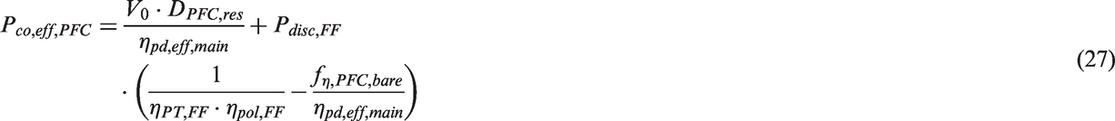
Assuming identical efficiencies for the non-BLI propulsive devices of the PFC and reference aircraft, i.e. ηpd,eff,main = ηpd,eff,Ref = ηpd,eff, the PSC for steady level flight can be formulated as follows
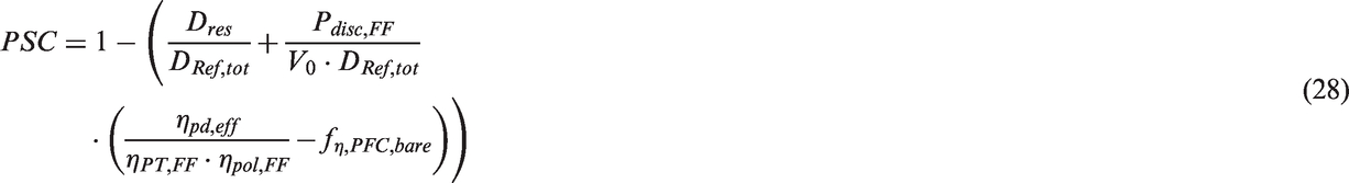
Equation (28) includes four basic terms presenting key aspects for PFC design optimality: The BLI efficiency factor
Evaluation of fuel savings
It should be noted that the PSC metric can also be assessed at the overall propulsion efficiency level by including

With the PSC metric available in terms of fuel flow rates, it can be directly used for an initial evaluation of PFC aircraft fuel consumption. The Breguet–Coffin equation in integral form solved for consumed fuel mass mf as a function of aircraft instantaneous gross weight mA/C,end at the end of a considered range segment ΔR serves as a basis for this


Solving equation (31) for the BLI PFC and the non-BLI reference aircraft while considering


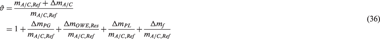
When assessing the performance of PFC aircraft against non-BLI aircraft, both the pure PSC and the ratio of aircraft gross weights are significant. It should be noted that the PSC itself is influenced by ϑ, as the induced drag of the PFC aircraft that is in included in DPFC,res can be directly geared to the non-BLI reference: For identical wing loadings and induced drag coefficient factors, the relation becomes DPFC,i = DRef,i·ϑ.
While vehicular efficiency quantification (equation (32)) necessitates an instantaneous ϑ at the considered operating point, the evaluation of fuel burn based on the solution of the Breguet–Coffin equation presented in equation (30) requires aircraft gross weight to be determined at the end of ΔR. Hence, equation (32) can be used to solve equation (30) for both aircraft and to analytically express the consumed fuel mass of the PFC aircraft

It can be seen that for PSC impact on PFC fuel savings versus cruise range.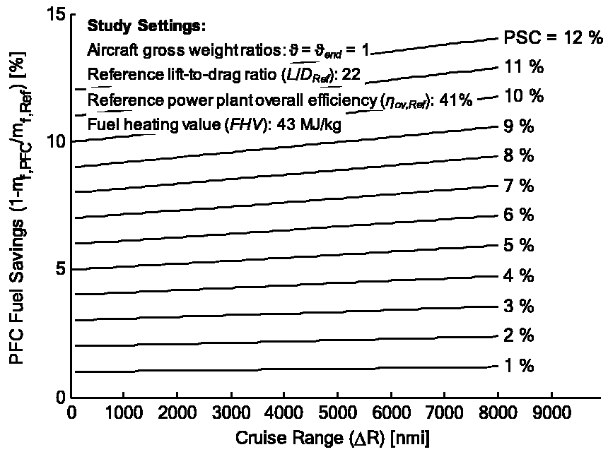
The PSC value for an actual PFC design can be obtained from equation (28), if PFC and reference aircraft share identical

For a given transport task, the change in payload mass

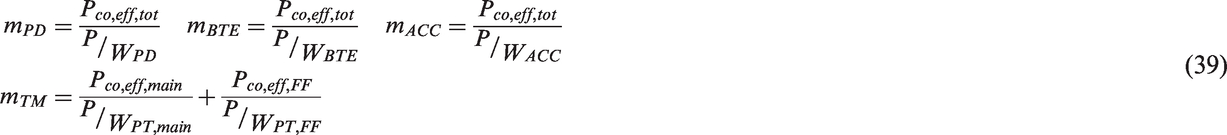
The weights of the propulsion groups in both aircraft cases (PFC and Ref) may be simply determined based on the weights of its principal component groups

While the assumption of
Setup of study
Aircraft application case
Top-level aircraft properties for the DisPURSAL and CENTRELINE reference aircraft.
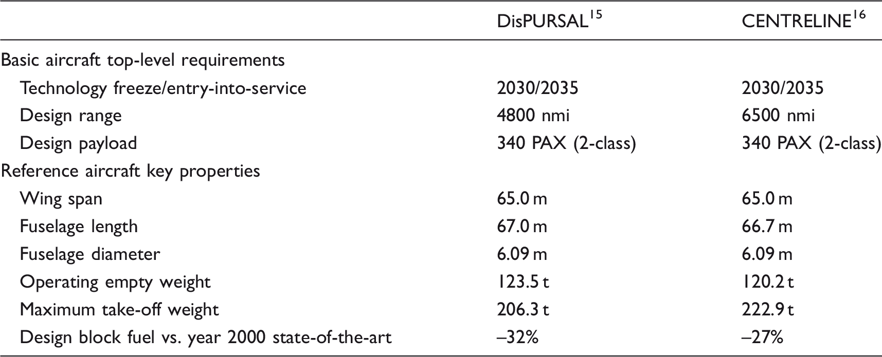
Cruise drag properties and propulsion efficiency figures representative for CENTRELINE R2035 aircraft (cf. also Peter et al.37).
Cruise at M0.82, FL350, ISA + 10 K; cL = 0.5.
Specific powers for the principle component groups of the CENTRELINE R2035 propulsion system acc. to Samuelsson et al. 30

w.r.t. Pco,eff at typical cruise point.
Baseline parametric settings
Beyond the reference aircraft application scenario, the analysis of the PFC power-saving potentials requires a few assumptions to be made and motivated. These refer to the aerodynamic interference of the bare PFC configuration and the adjacent aircraft components, i.e. the lifting surfaces and the under wing podded power plants, as well as the efficiency of power transmission from the core engine exit to the FF, and the degradation of the FF efficiency itself due to the ingestion of distorted inflow.
Typical sources of aerodynamic interference would be caused by the 3D flow at the wing–fuselage junction and the intersection of the fuselage and FF nacelle body with the empennage, especially in flight with incidence (pitch and yaw e ). While the aerodynamic inference between the wing and the fuselage at the fuselage–wing junction may be expected to be similar for best and balanced reference and PFC aircraft designs, for the empennage, configurations need to be considered that avoid aerodynamic interference with the FF nacelle as much as possible. Assuming a T-tail arrangement for the PFC configuration, the aerodynamic interference between the horizontal stabiliser and the bare PFC configuration is clearly reduced. The aerodynamic interference of the vertical fin and the FF nacelle remains in this case. More advanced solutions such as self-trimming wing configurations 31 might allow for significant size reductions or possibly the total omission of tail planes. The data basis of CFD aerodynamic results used for the present study is limited to 2D axisymmetric simulations of the bare PFC configuration. All residual drag components from adjacent aircraft components are retained invariant when changing from the non-BLI reference to the BLI PFC aircraft. This means, aerodynamic interference effects between the bare PFC configuration and the rest of the aircraft are not explicitly resolved, in the first instance. At the same time, reduction drag effects due to shrinking main engine nacelle sizes for the PFC aircraft f as well as the ingested wake momentum deficits emanating from the wing and tail plane root sections are not accounted for.
The wake fields of upstream aircraft components have a direct impact on the inflow distortion of the aft–fuselage BLI propulsor. The main effects include the wing downwash, fuselage upwash at non-zero incidence as well as the tail plane wakes. By interfering with the fuselage boundary layer flow these wake effects create additional distortion in the BLI propulsor inflow field through circumferential asymmetry, thereby impacting of the aerodynamic efficiency of the FF. The reduction of BLI fan aerodynamic efficiency ηpol,FF relative to fans operating under freestream inflow conditions has been previously investigated numerically and experimentally for various inflow distortion patterns. Gunn and Hall indicate an efficiency penalty between 1% and 2% for BLI fans in semi-buried engines configurations on the topside of a blended wing body aircraft. 32 Initial aerodynamic design and performance results for a FF propulsor under axisymmetrically distorted inflow have been produced as part of the CENTRELINE project by Castillo Pardo and Hall. 33 Relative to an optimised freestream inflow design Castillo Pardo and Hall predict a FF isentropic efficiency penalty between 0.5% and 1.0%. Based on an outer fan polytropic efficiency of the CENTRELINE reference power plants of ηpol,F,o = 94% this suggests a FF polytropic efficiency of ηpol,FF = 93%.
The FF power train efficiency ηPT,FF strongly depends on the transmission paradigm, which can be by electric, mechanical or pneumatic means. The considered options primarily considered in this study are turbo-electric, i.e. an electrically driven FF powered by generator off-takes from the main engines, and mechanical, i.e. via shaft and gearbox systems. An achievable turbo-electric power train efficiency based on conventional conducting, non-cyrogenic electric components typically is of the order of 90%, while all high temperature superconducting designs may be much closer to 100%. A mechanical transmission through a shaft and bearing system similar to a geared turbo fan engines possibly supplemented by two serial gear stages may be estimated at an efficiency of 98%. The core engine efficiencies ηco have been set identical for the BLI PFC and non-BLI reference aircraft, in the first instance. All studied cases use a FHV of 43 MJ/kg.
The focus of the present study is on steady-level flight at cruise conditions featuring a fuselage angle of attack of zero. With the 2D axisymmetric aerodynamic simulations, the analysis refers to aft-fuselage designs without upsweep. It should be noted that in reality, aft–fuselage upsweep will be a multi-disciplinary optimisation parameter trading aerodynamic penalties in terms of aft–fuselage pressure drag and FF performance penalties due to aerodynamic upwash effects, and structural weights reductions for example through relieved main landing gear length requirements during take-off rotation.
Study results
Aerodynamic shape refinement and optimisation
During DisPURSAL, an initial 2D axisymmetric aero-shaping for the bare PFC configuration based on semi-empirically derived design settings for FF size and pressure ratio
34
was iteratively refined based on a multi-disciplinary aircraft design exercise featuring CFD in-the-loop.
35
Starting from the refined baseline aero-shape, an initial CFD-based design space exploration was performed for alternative FF sizes and pressure ratios.
36
In the succeeding CENTRELINE project, a preliminary draft of the fuselage and FF nacelle aerodynamic geometry was generated based on previous design experience from DisPURSAL. The general fuselage dimensions, such as total fuselage length and diameter, were adopted from the CENTRELINE R2035 aircraft (cf. Peter et al.
37
). Based on preliminary design space analyses,
16
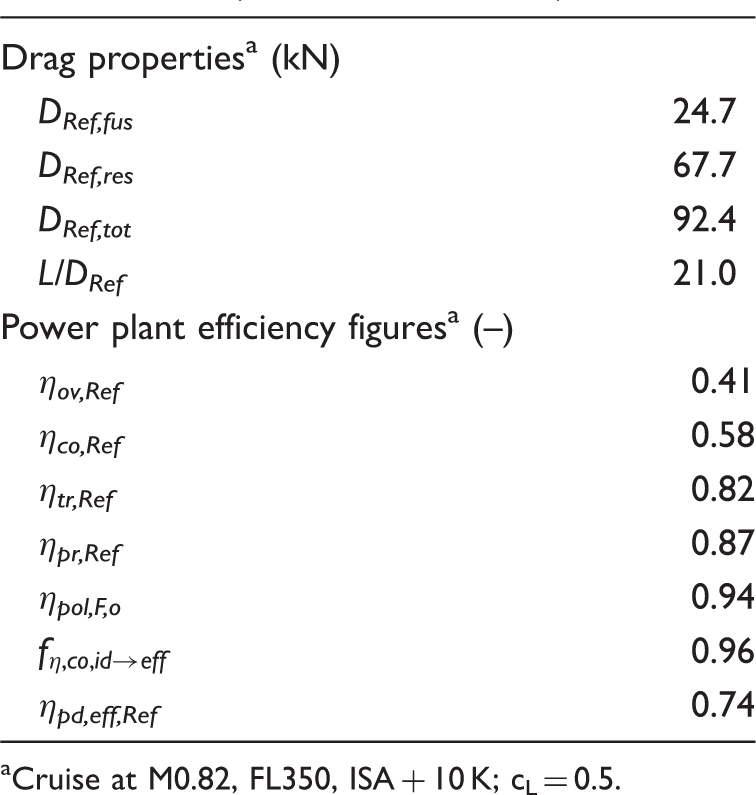
FF FPR was initially selected to be 1.40 and Pdisc,FF was constrained to 5.5 MW. Different from the FF aero-structural integration in DisPURSAL with the FF air intake located in front of the empennage, the geometric baseline in CENTRELINE assumed the FF to be far aft located along the fuselage central axis. The initial 2D axisymmetric shaping of the bare PFC configuration was incrementally improved based on engineering judgement and evaluated in CFD in order to maximise its aerodynamic efficiency. Modifications included nacelle incidence angle and aft body curvature improvements as well as increased fuselage boat tail length and the introduction of a gradual increase in hub diameter towards the exit of the duct, similar to those observed in state-of-the-art turbofan designs. An example of two different designs and their respective surface pressure distributions is shown in Figure 4. Comparison of the static pressure coefficient distribution of representative aero-shaping versions (Rev03 and Rev04) in cruise conditions (FL350, M0.82, ISA+10 K; FPRFF = 1.40).
As can be observed from the figure, the hub line of the fuselage near the duct exit is contracting much more in the case of the updated intermediate revision of the bare PFC design. In this way, the circumferential surface area is reduced and local surface normal vectors are better aligned, to reduce the pressure drag on the nacelle. Furthermore, it allows for a less cambered nacelle geometry at lower incidence angle for a given duct exit area. The contraction of the hub line at the fan location also helps to prevent flow separation at the hub due to the contraction of stream tube. Additionally, the length of the fuselage boat tail was increased, to increase the positive axial force on the body due the higher static pressure in the exhaust plume of the FF.
In order to achieve a step-change improvement in PFC aero-shaping beyond the intuitive refinement approach, a numerical optimisation process based on a parametric model of the axisymmetric PFC geometry was developed. Therefore, the fuselage geometry was represented by various non-uniform rational basis (NURB) splines, to allow for local changes in curvature and shape. The nacelle geometry was replicated using the Bezier–Parsec method.
38
In total, 23 parameters were required to represent the full bare PFC configuration. An automated framework was created around the CFD setup discussed in Aero-numerical analysis and shape optimisation approach section in order to perform the entire procedure from geometry creation to meshing, and from simulation to data post-processing. A quasi-random sampling approach (Latinised Partial Stratified Sampling
39
) was used to cover the large sampling space. With a mesh to simulation convergence success rate of close to 40%, over 2000 converged unique results were obtained. One-dimensional sensitivity studies were conducted to identify the most influential design parameters. The key parameters determined for the shape optimisation were the following: Freestream Mach number (M0) Flight altitude (h0) FF pressure ratio (FPRFF) FF duct height (h2) FF nozzle exit to fan front face area ratio (A18/A2) FF hub-to-tip ratio (rFF/RFF) FF relative axial position along the fuselage (xFF/Lfus)
Using these parameters, a surrogate model based on support vector machines 40 was constructed. A survey of the sample space revealed several promising designs, of which one design was selected as being most suitable for the CENTRELINE configuration. Taking the selected design as a starting point, a constrained gradient-based optimisation was carried out to obtain best bare PFC aero-shapings with regard to the fη,PFC,bare metric. For the CENTRELINE design cruise conditions (FL350, M0.82 ISA + 10 K) and a given Pdisc,FF constraint of 5.5 MW, the aerodynamic optimum was found at design settings of FPRFF =1.32, h2 = 0.73 m, A18/A2 = 0.68, rFF/RFF = 0.43 and xFF/Lfus = 0.92.
The progression of aerodynamic efficiency with each revision of the CENTRELINE bare PFC aero-shaping is presented in Figure 5 including Rev 06 obtained from the abovementioned numeric optimisation process. As can be seen from the figure, the actual shaping of Rev 06 does not deviate drastically from the initial PFC designs (cf. Figure 4). However, the combined effect of relatively small changes to the aft body curvature, nacelle incidence and duct height of the FF, leads to clear performance improvements measurable by the bare PFC net propulsive power for the given level of Pdisc,FF. Progression of aerodynamic efficiency during CENTRELINE bare PFC aero-shape refinement with design contour after optimisation of the main shape parameters.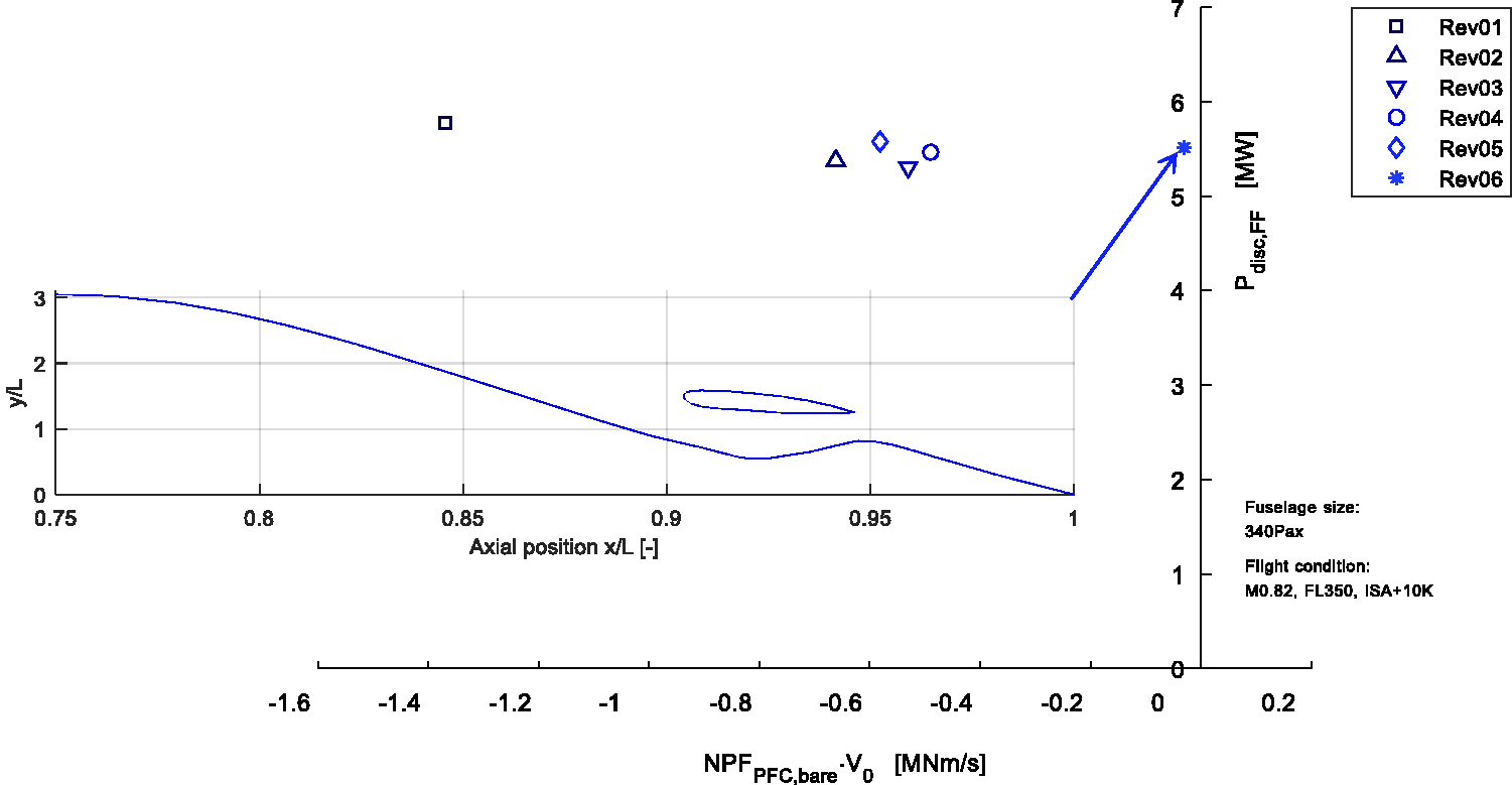
Analysis of aircraft power savings
In order to study optimality trends for PFC power savings, the entirety of PFC 2D aero-shaping cases evaluated in DisPURSAL and during CENTRELINE so far was taken into account. For this purpose, the studied aero-shaping cases were analysed with regard to the BLI efficiency factor for the bare PFC configurations (cf. equation (11)). A chart of Analysis of BLI efficiency factor for CENTRELINE and DisPURSAL aero-shapings.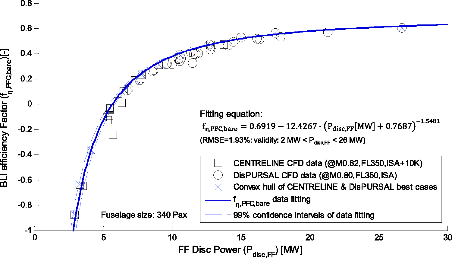
The shown bare PFC designs cover a wide range of Pdisc,FF. Below approximately 6 MW, the BLI efficiency factor fη,PFC,bare is negative due to a negative NPFPFC,bare. Hence, in this region the FF disc force Fdisc,FF is not sufficient to fully compensate the total retarding force acting on the bare PFC configuration. For increasing Pdisc,FF it can be seen that the BLI efficiency factor fη,PFC,bare improves strongly in the low-power region while the improvement trend flattens out towards the higher power region. As Pdisc,FF increases, the corresponding optimum FF face area grows as fan pressure ratio is limited for propulsive efficiency reasons. With growing face area the FF blade heights increasingly grow into the outer regions of the boundary layer profile where the local momentum deficit decreases rapidly. As such, the additionally ingested momentum deficit is reduced and the further gains from BLI are diminishing.
Given the power train design paradigms mainly followed in both projects, the CENTRELINE designs cover mostly the lower Pdisc,FF region while the DisPURSAL designs predominantly capture the high-power region. However, the best cases of both domains of bare PFC 2D aero-shaping consistently form a Pareto front with regard to fη,PFC,bare. This allows for the determination of a high-quality data fitting curve for the designs the form that convex hull of the pool of designs
The validity of the above fitting correlation applies to 340 passenger wide body aircraft with design cruise conditions at around M0.82, FL350 ISA + 10 K and covers Pdisc,FF between approximately 2 and 26 MW. The correlation can be immediately used as a design heuristic in order to analytically compute the PSC according to equation (28). Validation plots for the PSC mapping quality based on equation (40) are presented in Figure 7, showing that an evaluation of equation (28) using the fη,PFC,bare fitting curve yields very good agreement – both in absolute values and in general trending behaviour – with a direct PSC evaluation based of the actual CFD data produced by ONERA and TU Delft during DisPURSAL and CENTRELINE, respectively. Analysis of PSC for CENTRELINE and DisPURSAL best aero-design cases.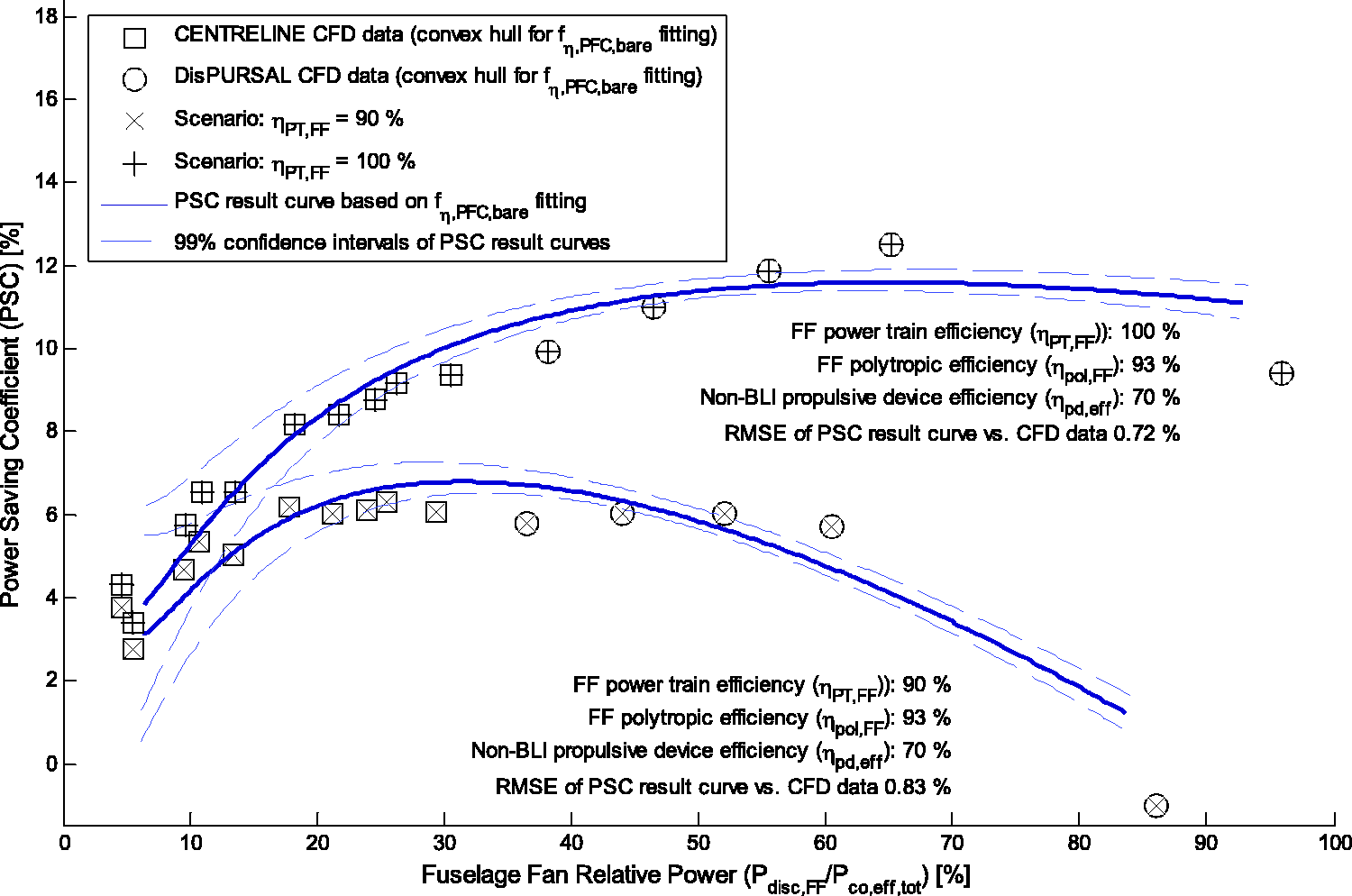
The plots in Figure 7 display the best bare PFC aero-shapings from CENTRELINE and DisPURSAL indicated as convex hull points in the previous figure. For the design cases, two scenarios of FF power train efficiency ηPT,FF are visualised – an ideal one featuring ηPT,FF = 100% and a more conservative one with ηPT,FF = 90%. The obtained PSC values are plotted against the relative FF power, i.e. the ratio of ideal power absorbed by the FF disc to the total effective core engine excess power required for the PFC aircraft
Constellations for optimum power savings
In order to systematically gauge the sensitivity of optimum PFC power savings and corresponding aircraft design impact, parametric analyses of PSC (cf. equation (28)) based on the presented fη,PFC,bare fitting were performed. Optimum results with regard to the maximum PSC and corresponding Identification of optimum PSC and corresponding FF relative powers for various power train and non-BLI propulsive device efficiencies.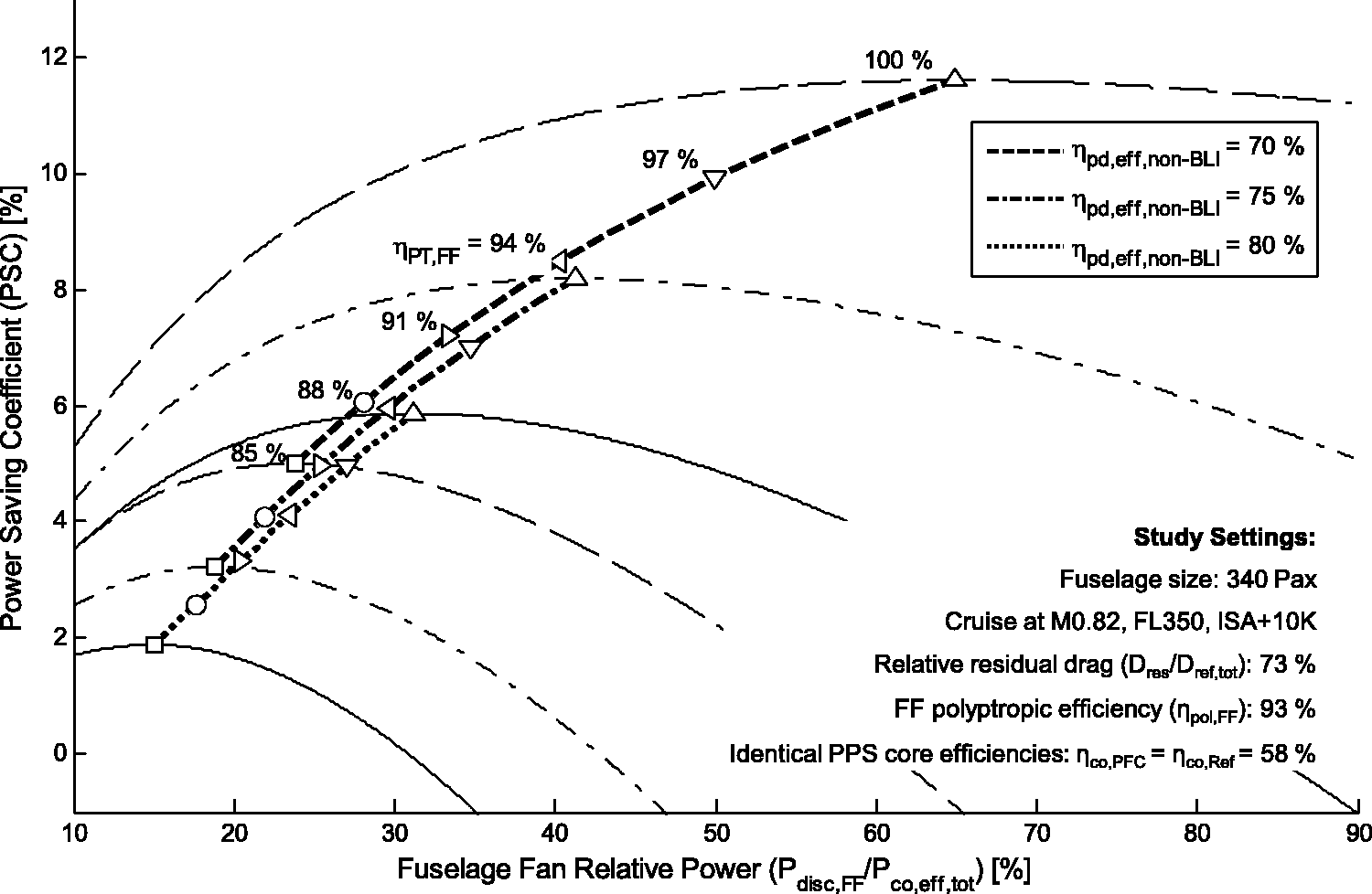
Figure 8 quantifies the importance of high FF transmission efficiencies ηPT,FF in order to achieve significant PSC values. Comparing, for instance, a turbo-electric power transmission featuring ηPT,FF =91% and a mechanical power train with ηPT,FF =98% assuming ηpd.eff.non-BLI = 70%,f the maximum PSC for the mechanical case would yield 10.4% while maximum PSC for the turbo-electric case would be reduced by 3.3% down to a value of 7.1%. The corresponding optimum
Beyond the pure sensitivity of maximum PSC and optimum design due to variations in ηPT,FF, Figure 8 also shows strong impact of the effective efficiency of the involved non-BLI propulsive devices – i.e. the reference and the PFC main engines ηpd.eff.non-BLI – on optimum PFC design and the attainable power savings. Increasing ηpd.eff.non-BLI raises the benchmark level for BLI propulsion, and thus, reduces the achievable PSC for a given level of ηPT,FF. At the same time, the optimum for FF relative power is decreased, indicating more power to be directed to the main engine propulsive devices. For the above defined turbo-electric and mechanical FF power transmission scenario cases, an increase in ηpd.eff.non-BLI from 70% to 80% yields a reduction in maximum PSC by 3.9% and 5.2%, respectively.
Despite its insightful nature with regard to the vehicular efficiency of PFC aircraft, the PSC metric does not fully account for effects of changes in aircraft empty weight due the novel type of propulsion system and its airframe integration. Also, the effect of weight reduction due to varying fuel consumption along a given flight distance is not captured. Therefore, Figure 9 presents the PFC fuel burn savings based on the modified Breguet–Coffin equation (equation (34)) for a 340 passenger, 6500 nmi air transport task. System weight impact on optimum PFC fuel savings and corresponding FF relative power levels.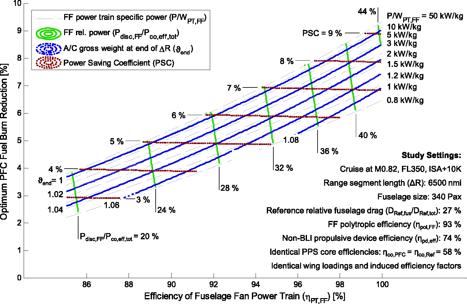
The optimum PFC fuel savings in Figure 9 are plotted against ηPT,FF. The specific power of the FF power train P/WPT,FF is shown as an array parameter. The ratio of aircraft gross weights between the PFC and reference aircraft design at the end of the considered flight segment ϑ
end
is displayed as dash-dotted contours in blue colour. Optimum PFC design is indicated as solid contours of
The PFC fuel improvement trends versus increasing ηPT,FF shown in Figure 9 are consistent with the corresponding maximum PSC trends displayed in Figure 8. A direct trade between ηPT,FF and the ratio of PFC and reference aircraft masses is visible. With the ϑ
end
= 1 line indicating the maximum fuel saving curve and corresponding optimum PFC design for the given transport task without PFC empty weight penalty, the fuel impact with increasing PFC empty weight penalty (ϑ
end
> 1) is obvious. The penalty in PFC fuel savings is in the order of 0.3% per percent increase in ϑ
end
with a slightly progressive trend with growing ϑ
end
. If propulsion installation weight penalties are neglected, i.e.
Conclusion and further work
The paper provides a rigorous methodical approach for the evaluation of the power-saving potentials of PFC aircraft configurations. Analytical formulation for the PSC metric was introduced and the classic Breguet–Coffin range equation was extended for the analytical assessment of BLI aircraft. The analytical formulation was applied to the identification of optimum PFC power savings together with CFD numerical results of refined and optimised 2D aero-shapings of the bare PFC configuration, i.e. fuselage body including the aft–fuselage BLI propulsive device, obtained during the DisPURSAL and CENTRELINE projects. A common heuristic for the BLI efficiency factor was derived from the best aero-shaping cases of both projects. Using the derived PFC design and performance heuristic, maximum power savings and corresponding optimum PFC design settings were parametrically analysed and discussed with regard to relevant power train configurations. It was found that the optimum PFC aircraft design is strongly dependent on the efficiency levels of the transmission system and the effective efficiency levels of the involved non-BLI propulsive devices.
Improving transmission system efficiency increases the achievable power savings, and, shifts the optimum ratio of FF to total fan power to higher values. If the effective propulsive device efficiency of the reference aircraft and PFC main engines increases, the attainable PFC power savings are reduced and optimum relative FF power levels decrease. In a direct comparison between typical settings for mechanical and conventionally conducting turbo-electric scenarios for the power transmission from the core engine exit to the FF, the mechanical option features higher fuel burn reduction potentials than turbo-electric transmission, if FF aero-structural integration can be mastered. The analysis results confirm the necessity for a highly optimised PFC aero-shaping, an ultra-efficient FF power train and minimum installation weight penalty, in order to achieve high fuel burn savings for a PFC aircraft configuration.
The presented optimality analyses focused explicitly on a 340 passenger medium-to-long range aircraft application with design cruise conditions at M0.82, FL350, ISA + 10 K based on 2D axisymmetric aero-shaping results. However, by parametric extension of the developed BLI efficiency factor heuristic, the methodology introduced in the paper directly enables the PFC power savings evaluation for aircraft of different sizes under 3D aero-shaping paradigms. This also includes the investigation of alternative flight techniques.
Recommended future work involves a more detailed resolution of aerodynamic interference effects between the bare PFC configuration and the adjacent aircraft components and the analysis of the 3D aero-shaping implications on the power-saving potentials of PFC aircraft configurations. As part of the presented study, possible synergy potentials with additional annexed technologies were highlighted. For this purpose, future work should consider PFC technology as a key item within an overall technology package for ultra-efficient transport aircraft and explore technological synergy potentials in a systematic way. This should include ultra-efficient wing aerodynamics including hybrid and natural flow laminarity and self-trimming wing properties, the combination with radically advanced aero engine cycle technologies, as well as the application of alternative energy options such as liquid hydrogen fuel.
Footnotes
Acknowledgements
The authors convey their gratitude to Richard Grenon and Jean-Luc Godard from ONERA – The French Aerospace Lab for kindly providing the CFD results obtained from the DisPURSAL design studies, as well as Reynard de Vries for a helpful exchange on vehicular efficiency considerations. Arne Seitz would like to thank Markus Nickl for fruitful discussions on the effective core engine excess power parameter, and, Mirko Hornung for valuable feedback and advice.
Declaration of Conflicting Interests
The author(s) declared no potential conflicts of interest with respect to the research, authorship, and/or publication of this article.
Funding
The author(s) disclosed receipt of the following financial support for the research, authorship, and/or publication of this article: The CENTRELINE project has received funding from the European Union’s Horizon 2020 research and innovation programme under Grant Agreement No. 723242. The DisPURSAL project has received funding from the European Union’s Seventh Framework Programme (FP7) under Grant Agreement No. 323013.