
Abstract
A morphing leading edge produces a continuous aerodynamic surface that has no gaps between the moving and fixed parts. The continuous seamless shape has the potential to reduce drag, compared to conventional devices, such as slats that produce a discrete aerofoil shape change. However, the morphing leading edge has to achieve the required target shape by deforming from the baseline shape under the aerodynamic loads. In this paper, a conceptual-level method is proposed to evaluate the morphing leading edge structure. The feasibility of the skin design is validated by checking the failure index of the composite when the morphing leading edge undergoes the shape change. The stiffness of the morphing leading edge skin is spatially varied using variable lamina angles, and comparisons to the skin with constant stiffness are made to highlight its potential to reduce the actuation forces. The structural analysis is performed using a two-level structural optimisation scheme. The first level optimisation is applied to find the optimised structural properties of the leading edge skin and the associated actuation forces. The structural properties of the skin are given as a stiffness distribution, which is controlled by a B spline interpolation function. In the second level, the design solution of the skin is investigated. The skin is assumed to be made of variable stiffness composite. The stack sequence of the composite is optimised element-by-element to match the target stiffness. A failure criterion is employed to obtain the failure index when the leading edge is actuated from the baseline shape to the target shape. Test cases are given to demonstrate that the optimisation scheme is able to provide the stiffness distribution of the leading edge skin and the actuation forces can be reduced by using a spatially variable stiffness skin.
Introduction
The morphing leading edge has been the subject of research for the last few years since it has the potential to improve aerodynamic performance. Although the morphing leading edge is still under development and the detailed technical approach varies for different realisations of the concept, a key feature is the specifically-designed smooth shape change, in contrast to conventional slats which have a gap between the leading edge device and the main wing structure. The continuous, seamless shape contributes to the laminar flow around the aerofoil, which helps to reduce drag. The aerodynamic requirements drive the structural design of the leading edge, especially for the leading edge skin. The skin will need to carry the local aerodynamic loads and undergo the shape-change.
There have been several research projects on the morphing leading edge. The ‘droop-nose’ leading edge was investigated extensively in DLR (German Aerospace Center).1–5 A process chain was proposed to design the leading edge structure, as well as the internal actuation mechanism. 6 A specific composite was developed for the leading edge skin, 7 which was a composite material based on a compliant matrix and embedded fibres. The droop-nose design was also applied at the wingtip, which was supported by an internal compliant structure based on a superelastic nickel–titanium alloy. 8 Ground and wind tunnel tests of the droop-nose morphing wingtip were performed to validate the numerical models and the optimisation tools. The droop-nose leading edge was able to change its shape when it was subject to the external aerodynamic loads with some reasonable errors between the experimental and computational results. 9 Some lessons were learned from the wind tunnel tests, which provided suggestions on the design chain, the topology optimisation environment, the actuation mechanism and the superelastic materials. 10 The testing of a full-scale droop-nose model is underway in the SFB880 project, which will have a larger droop deflection and thus lead to more challenging structural requirements. 11
Experimental evaluation was performed in the Leading Edge Actuation Topology Design and Demonstrator (LeaTop) project. 12 The leading edge skin strain was measured and compared to the numerical simulation results, and it was found that morphing of the leading edge was dominated by bending rather than stretching the skin. The locking capability of the actuation mechanism was also tested to verify that the aerodynamic loads can be transferred by the mechanism to the main spar.
A morphing leading edge, which can undergo both bending and stretching, was developed in the Mission Optimised Smart Structures (MOSS) project.13,14 The aerodynamic optimisation was performed with the stretching of the leading edge included in the aerofoil geometry. 13 To make the stretchable structure possible, a novel skin material is developed using a nanocomposite, which is based on the carbon nanotubes and thermoplastic polyurethane. To increase the stiffness to transfer the aerodynamic loads, the skin was supported by 3D printed substructures, which allowed for the stretchable shape change of the skin. 14
The design and optimisation considering both the morphing leading edge and trailing edges was also presented. 8 A two-level optimisation tool was applied, in which the aerofoil shape was determined in the first level, and the inner compliant structure was designed in the second level. 15
In addition to the morphing capability, a multifunctional study of the morphing leading edge was also necessary to provide an enhanced morphing wing design. A bird-strike protection system was developed for an adaptive droop-nose leading edge in the Smart Intelligent Aircraft Structures (SARISTU) project, as part of the morphing skin could be thin. 16 Numerical simulation was used to develop the system and a bird-strike test was performed to validate it. Other functionalities considered include the surface protection from sand and rain erosion, the deicing system and the lightning strike protection in the SARISTU project. 16 An experimental demonstrator was developed in the Clean Sky project to integrate the synthetic jet, the optical fibres, the ice-protection system and the shape memory alloy actuator into the morphing leading edge. 17 The demonstrator was manufactured with carbon fibre composites and was tested in a climate wind tunnel to validate its functionality under the environmental icing conditions.
Changing the shape and carrying aerodynamic loads simultaneously is very challenging for the design of the leading edge skin as the deformation might cause failure of the skin. In a leading edge design, a glass fibre reinforced composite skin and an aluminium alloy skin were compared. 18 The composite skin could reach the target deflection but could not satisfy the strength requirements, and thus a metallic skin was chosen as the better solution based on the strength requirements. Composite skins supported by corrugated structures were investigated for the morphing leading edge, although it was found that a corrugated skin did not have significant advantages. 19 A chiral structure was also evaluated as the internal structure of the morphing aerofoil. 20
In this paper, the influence of the variable stiffness of the leading edge skin is investigated. A skin with a spatially variable stiffness could be beneficial and satisfy the requirements simultaneously: the high stiffness can help to carry loads while the low stiffness makes the shape change easier and demands reduced actuation forces.
For composite skins employed in the morphing leading design, the stiffness variation can be achieved by changing the lamination thickness (number of layers), such as in the droop-nose.2,4 Alternatively, the variable stiffness skin may be introduced by changing the lamina angles, 21 although in the literature the stack sequence was encapsulated by axial and bending stiffnesses parameters to reduce the number of design variables. Varying fibre angle could lead to a continuous stiffness distribution of leading edge skin and varying the skin thickness would lead to a discrete stiffness distribution.
In the current study, the variable stiffness of the leading edge skin is achieved by varying lamina angles and the potential benefits of introducing the variable stiffness will be compared directly to the skin with constant stiffness. The composite failure index will also be obtained explicitly to validate the design.
The detailed design of the leading edge structure is not considered at this stage. However, the evaluation process is still crucial because of the following two aspects:
To determine the feasibility of the candidate structural solutions in the conceptual level study. Even at this stage the determination of a failure index for the composite skin is desirable. To investigate the different structural concepts of the leading edge. The performance of constant and variable stiffness skins are compared in this paper, and the benefits of using a variable stiffness skin are demonstrated.
In the following sections, the model of the leading edge will be introduced first. The leading edge is investigated using simplified two-dimensional (2D) models. Secondly, a two-level optimisation scheme is established to determine the optimised leading edge design. The stiffness distribution of the leading edge skin will be predicted in the first level of optimisation, and the tailoring of the skin will be implemented in the second level. Although the leading edge skin is the main focus in this paper, the corresponding actuation forces are included in the model, and a simple approach is applied to determine the smallest actuation forces. Test cases will be performed to demonstrate the proposed approach. The composite failure index will be obtained, and the comparisons between the variable stiffness skin and the constant stiffness skin will be made.
Model definition
Finite element model employed
The schematic of the leading edge structure is shown in Figure 1. The leading edge shape resembles the NACA65(3)218 aerofoil. The chordwise direction is along the x-axis, and the spanwise direction is along the z-axis. Four omega stringers are shown as Stringer 1, 2, 3 and 4 in sequence along the counter-clockwise direction. Stringer 2 and Stringer 3 are assumed to be driven by the actuation mechanism, and the other two are only used to stiffen the skin against the aerodynamic loads. As this conceptual level investigation is focused on the leading edge skin, the details of the actuation mechanism are not included. A local coordinate system (t–n–z) is also shown with the n-axis representing the normal direction and the t-axis representing the tangent direction of the leading edge skin.
Schematic of the leading edge structure.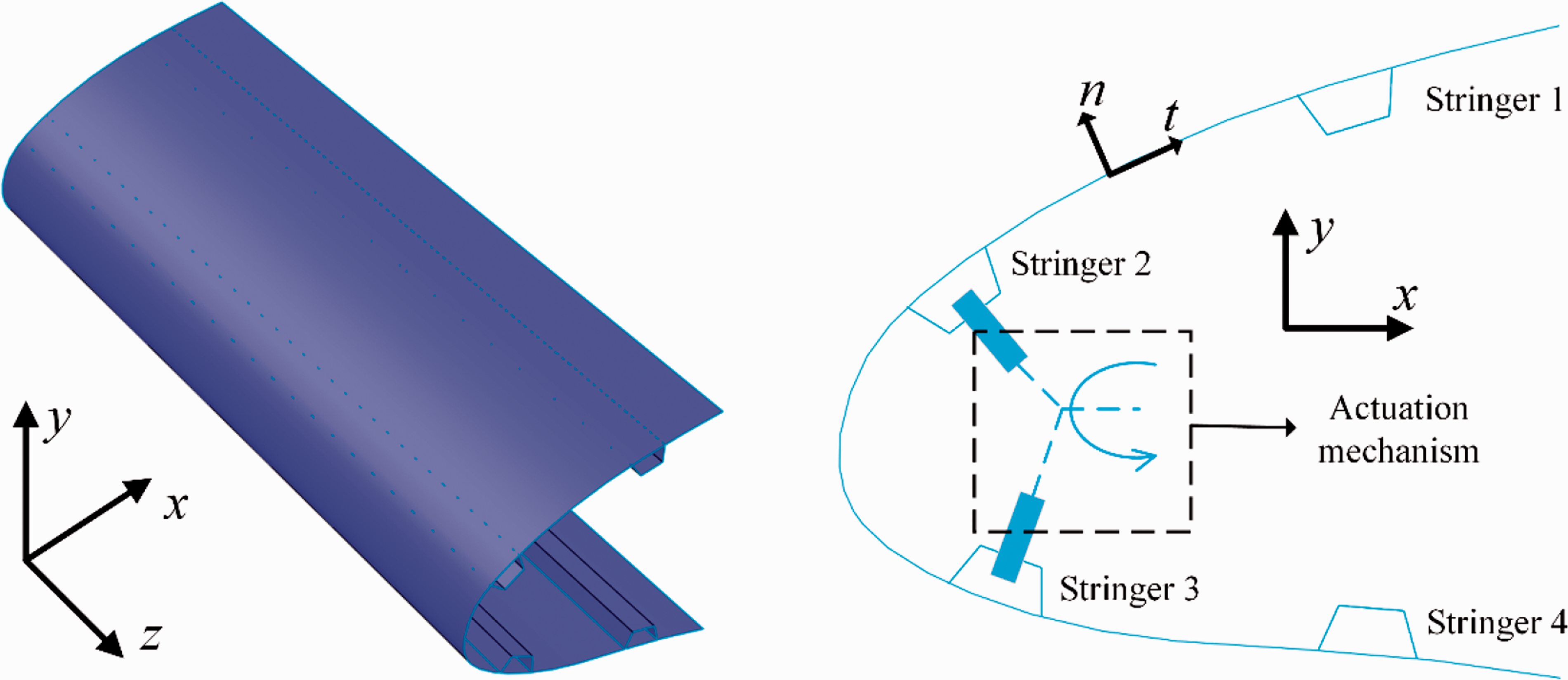
As shown in Figure 2(a), the leading edge structure is modelled as a 2D structure. Simplifying the structure into 2D reduces the geometry and structural variables in the model, which speeds up the analysis and optimisation of the leading edge structure, although a 3D aerodynamic and structural analysis will still be necessary for the detailed design.
(a) Sketch of the finite element model; (b) verification of the in-house finite element model.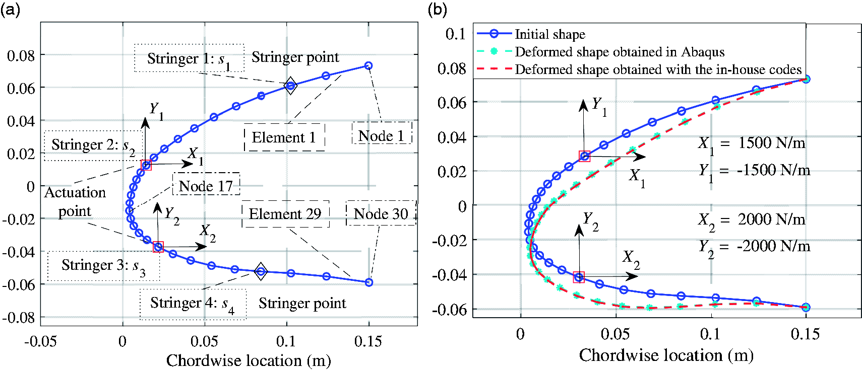
The 2D structural model is built in MATLAB so that the optimisation of the structure can be performed directly. Euler–Bernoulli beam elements are used to model the leading edge skin and each node has three degrees of freedom, i.e. the axial deflection u, the vertical deflection v, and the beam cross-section rotation α, which are sufficient to predict the deformation of the leading edge in the 2D cases. Only linear analysis is performed as the required shape change is not very large. The meshing of the structure is determined by the aerofoil coordinate points since their number is sufficient for the convergence of the structural model. The numbering order of the elements and nodes follows the counter-clockwise direction as shown in Figure 2(a), which results in 30 nodes in total. Node 1 and Node 30 correspond to the ends of the leading edge skin, and Node 17 corresponds to the frontmost node of the skin, which has the smallest x coordinate and separates the leading edge skin into two parts. The structural properties of the 2D model are determined by the extension stiffness (EA) and the bending stiffness (EI). The extension stiffness is assumed to be much larger than the bending stiffness so that the in-plane extension of the structure is negligible and the shape change of the leading edge is achieved by the bending of the beam elements.
In the 2D model, the design of the stringer cannot be fully accomplished since only partial stiffness information can be obtained. The other parameters of the stringers can only be determined if the detailed design of the stringers is performed using 3D models. In addition to the omega stringer, other types of stringers, such as the T stringer, may also be applied in the leading edge structure. Thus, the current research will not consider the details of the stringer, and the influence of the stringers is included by increasing the bending stiffnesses of the corresponding beam elements. Figure 2(a) highlights the structural nodes, which represent the locations of the stringers, with the black diamond markers and red square markers, and the stiffnesses of the two beam elements next to the highlighted structural node are increased to include the effect of the stringer. The node number of the specified structural node is denoted as si (i = 1, 2, 3, 4). The location of the stringer can then be changed by changing the variable si (i = 1, 2, 3, 4).
The leading edge structure is assumed to be driven by an actuation mechanism, which is connected to the leading edge skin at Stringer 2 and Stringer 3. The actuation forces are then applied to the structural nodes directly, which are highlighted by the red square markers and called ‘actuation points’ in this paper. Force components per unit span in the x and y directions are applied, which are denoted by Xi, and Yi (i = 1, 2) respectively. A small local moment is introduced to model the offset of the actuation point, which is determined by the size of the stringer and actuation mechanism. The magnitude of the local moment is controlled by the prescribed moment arm, which is set to 2% of the chord for the current study. The other two structural nodes highlighted by the black diamond markers are not subject to the actuation forces, and are called ‘stringer points.’
Verification of the 2D structural model is undertaken by comparison to the commercial FEM software Abaqus®. A test case compared to the Abaqus beam element is shown in Figure 2(b) using the linear analysis in Abaqus®. The chord is 1 m, and the leading edge accounts for 15% of the chord. The spanwise length is 0.1 m and the thickness of the skin is 1.5 mm. Isotropic material is used in the test case. The Young’s modulus is 69 GPa and Poisson’s ratio is 0.3. The same number of elements and nodes are used in the Abaqus model and the in-house MATLAB model. Although the in-house finite element analysis uses Euler–Bernoulli beam elements, the beam element B31 is adopted in Abaqus®, which allows for transverse shear deformation and can simulate both thick and slender beams. 22 To verify the accuracy of the deformation predictions, actuation forces are applied at the actuation points, which are located at Node 8 and Node 23 respectively in the verification. The deformed shapes obtained from Abaqus® and in-house MATLAB codes are shown in Figure 2(b). The maximum error of the deformed shape is less than 0.1% of the chord in this case, which shows a good agreement in terms of the shape prediction capability between the in-house codes and the Abaqus model.
Concept of a variable stiffness skin
The stiffness of the leading edge skin is assumed to be spatially variable. A skin with high stiffness can help to carry the aerodynamic loads, while a lower stiffness is able to reduce the actuation forces. The variable stiffness distribution in the finite element model is generated using B spline interpolation. Employing B spline interpolation rather than defining the structural property for each element reduces the number of optimisation variables and controls the range of the stiffness at the same time.
The morphing leading edge skin realises the variable stiffness through composites in the current study. The variable stiffness composites have been investigated to increase the buckling loads of a composite plate, 23 to increase the capability of load-carrying 24 and to improve aircraft performance. 25 For the morphing leading edge, composites can generate variable stiffness by tailoring the lamination thickness 4 or by changing the lamina angles. 21 The current study investigates the potential to vary the stiffness by changing the lamina angles. Compared to the change of the lamination thickness, the variable lamina angle allows a continuous change of stiffness rather than a discrete stiffness distribution, which might enable the target shape to be reached more closely. The potential to reduce the actuation forces is investigated and a failure model is employed to check whether the composite is reasonable when the leading edge is changed from the baseline to the target shape. It should be noted that the current research is focused on the potential of applying variable lamina angles in the leading edge skin. The practical manufacturing method is not considered, but the manufactured leading edge skin should satisfy the requirements of the shape, and the surface waviness and roughness, as defined in the literature. 26 Automated fiber placement could be a potential manufacturing method although more research is needed for its application to the morphing leading edge.
Optimisation scheme
Workflow of the structural design of the morphing leading edge
The structural analysis works sequentially after the aerodynamic analysis. Before the structural design of the leading edge, aerodynamic optimisation is employed to find the target shape according to the flight conditions. Figure 3 shows the baseline and target shapes of the leading edge in the current study, where the morphing leading edge accounts for 15% of the chord.
Baseline and target shapes of the leading edge.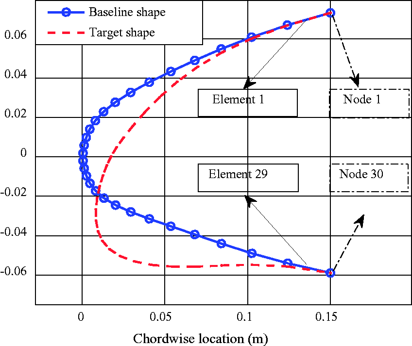
The baseline shape resembles the NACA65(3)218 aerofoil, and the target shape is obtained by the multi-objective optimisation of a regional transport aircraft, where the maximum lift coefficient and the lift-to-drag ratio with 70% of the maximum lift coefficient 27 are optimised when the Reynolds number is 9 × 10⁶ and the Mach number is 0.15. The detailed aerodynamic optimisation is not the subject of this paper. The current target shape is reconstructed by B splines, and more details of the aerodynamic analysis can be found in Magrini et al.27,28 A similar approach has been applied to optimise the aerofoil of the S4 unmanned aerial system, 29 in which part of the skin was flexible to introduce the shape change of the aerofoil and the aerodynamic optimisation was used to reduce the drag.
The baseline and target shapes are provided to the structural model as external sources and the morphing capability is validated by deforming to the target shape from the baseline shape. Aerodynamic loads, which are calculated for the target shape at the corresponding flight conditions, are applied directly to the structural nodes and remain unchanged in the structural optimisation. This method inherently decouples the aerodynamic analysis and the structural analysis, which allows the parallel development of the aerodynamic and structural models and helps to reduce the computational time. An aero-structure analysis is performed after the optimisation of the leading edge in the “Post-optimisation aero-structure analysis” section, which shows a negligible deformation and indicates the feasibility of the optimisation scheme.
For the test cases considered in this paper, 30 nodes and 29 elements are used for the finite element model, the chord is 1 m and the spanwise length is 0.1 m for the structural analysis. As shown in Figure 4, the design of the leading edge skin is achieved through two levels of structural optimisation. The first level optimisation will find the optimised bending stiffness distribution of the leading edge skin, the actuation forces and the stringers’ parameters, which are needed for the shape change. The results of the skin stiffness are then given to the second level optimisation, which tries to match the stiffness distribution by tailoring the lamination along the leading edge. The first level optimisation will find whether the variable stiffness skin can lead to a deformed shape that is close to the target shape. And the second level optimisation will investigate the composite lay-up to provide the variable stiffness.
Workflow of the optimisation scheme.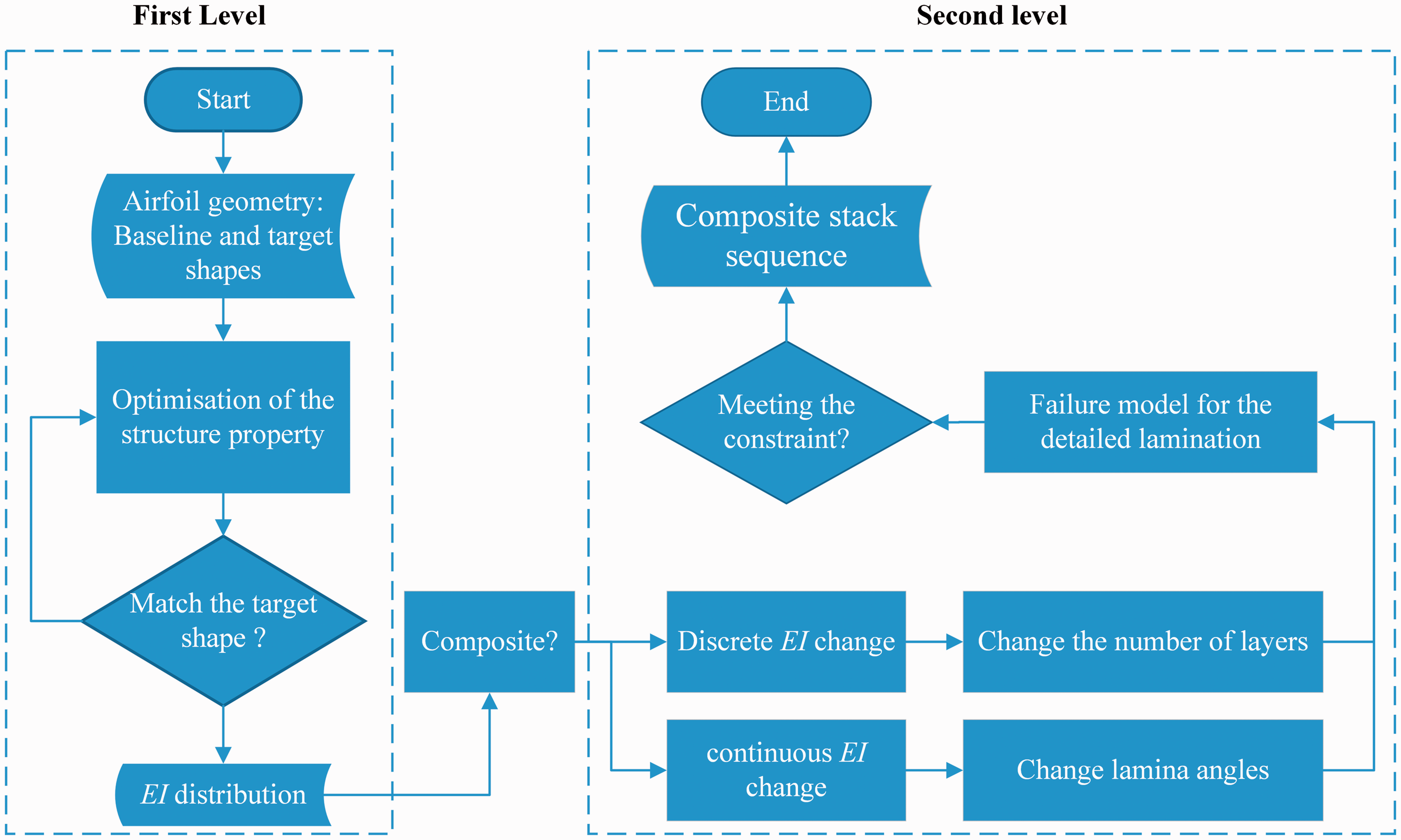
Since the (bending) stiffness of the skin is variable in the first level optimisation, there may exist more than one solution for the skin lay-up as long as the stiffness in each element of the model can be matched. To ensure the availability of a stack sequence that satisfies the stiffness distribution, the stiffness range in the first level optimisation should not exceed the stiffness range of the variable stiffness composite employed in the second level. Also, the stiffness slope in the first level should consider the limitation of composite manufacturing. For the variable stiffness composite based on the lamina angle variation, the maximum fibre curvature during manufacturing will influence the highest possible stiffness slope.
First level optimisation setup
Optimisation variables in the first level.
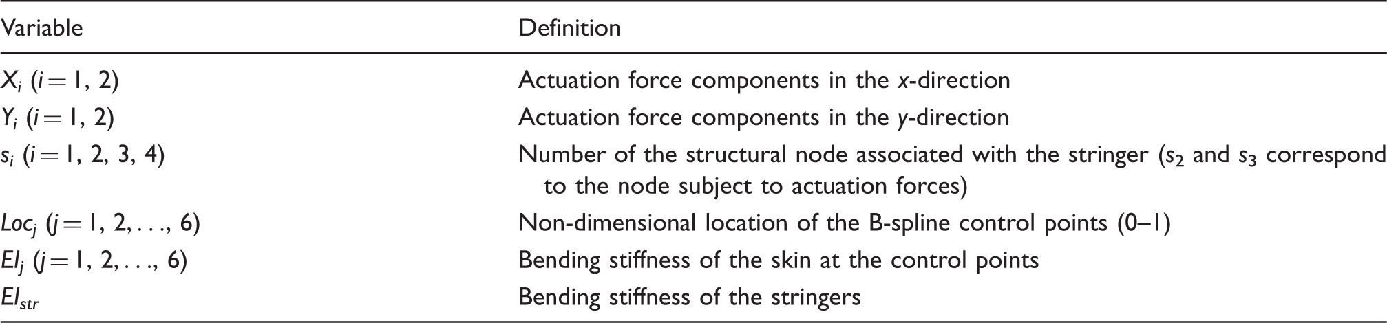
Except for the variables of the actuation points and stringers, six control points are used to interpolate the stiffness distribution, and each control point is parameterised by its position and bending stiffness. The ranges of the actuation forces and the stiffness are linked. Since the objective is to match the target shape, the actuation forces are not minimised directly. A series of optimisation tests is needed to find the smallest actuation force range. The details of the range of the actuation forces are discussed in Section 4, together with the range of stiffness. Two actuation points (s2 and s3) are allocated on the upper and lower surfaces respectively. Two extra nodes (s1 and s4) are used to represent the stringers without actuation forces.
The objective function of the structural optimisation represents the difference between the target shape and the baseline shape. The mean squared error (MSE) between their coordinate points is used, and considering the shape differences for all points, is expressed as

The stiffness gradient of the skin, ∇EI, is constrained in the optimisation to ensure the stiffness change is sufficiently moderate. A curvature constraint is also included to avoid significant deformation in the optimisation and also to help eliminate impractical skin distributions. Enough space should also be added between two adjacent stringers to allow for the actuator installation. The constraints are given by

The allowable stiffness gradient,
The genetic algorithm (GA) in the MATLAB global optimisation toolbox 32 is used. The population size is 200, the number of stall generations is 200 and the tolerance of the function is 1 × 10⁻⁹.
Second level optimisation setup
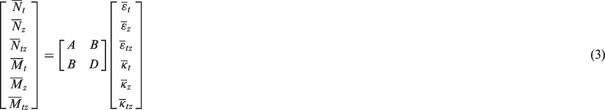
In the second level, the leading edge skin is tailored to satisfy the required bending stiffness distribution. Variable stiffness composites are employed although other solutions may also be used. The bending stiffness, EI, from the first level optimisation is related to the ABD matrix of the composite lamination. The stiffness matrix of the lamination can be expressed in the local coordinate system (t–z–n) of the leading edge skin as

The objective is to minimise the stiffness difference between the first and second level in each corresponding element of the skin, given by

For the laminated composites, there may exist more than one solution to provide the required stiffness if no other constraints are taken into account. The current study adopts a simplified design by introducing variable angles to some layers in the given stack sequences of the straight fibre composites. The lamination is assumed to remain symmetrical and balanced with constant thickness of each layer. The number of variables is then reduced significantly if these assumptions are taken into account. Although the reduced number of variables will generate a smaller design space, the influence of the variable stiffness skins can still be highlighted by making direct comparisons to constant stiffness skins based on straight fibre composites.
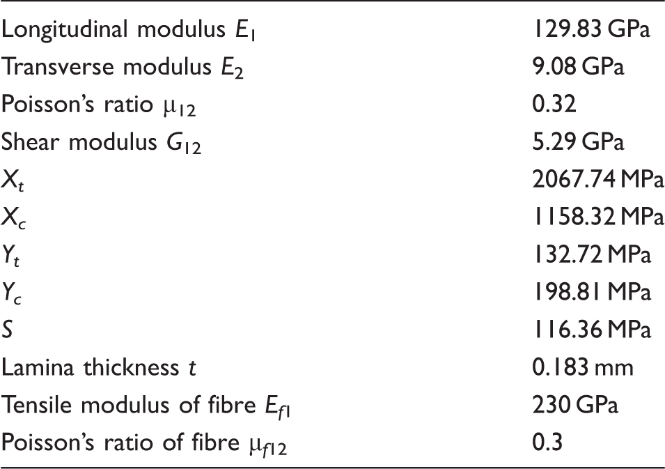
Puck’s failure theory is applied to investigate the failure index of the composites. Puck’s failure theory separates the failure of the composite into fibre failure and inter-fibre fracture, and three different failure modes are considered in the inter-fibre scenario.30,31 For the fibre failure

For the inter-fibre fracture, there exist three different modes, expressed as
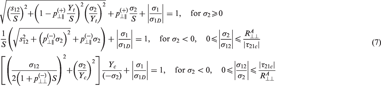
where
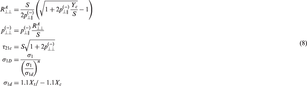
Here, σ1, σ2 and s12 are the stresses along the fibre direction, perpendicular to the fibre direction and the in-plane shear stress, respectively. The factor mσf represents a ‘stress magnification effect’ caused by the different moduli of the fibre and matrix. It is suggested that mσf = 1.1 for carbon fibre reinforced composites, and mσf = 1.3 for glass fibre reinforced composites.
30
Some guidelines are also provided in Puck et al.,
33
which suggests the inclinations parameters are
Lamina parameters.
The failure analysis is currently performed after the optimisation as the failure index was found to be smaller than 1, which allows a full exploration of the design space. The current analysis does not take account cyclic loading and the environment temperature, but these effects may be considered in the optimisation scheme in future work.
The second level optimisation is also performed by the MATLAB GA optimisation toolbox. 32 Since the number of variables is smaller than the first level, a smaller population and fewer generations are used to reduce the computational cost.
Results and discussions
Results using constant stiffness skin
Before the variable stiffness skin is investigated, the skin with constant stiffness is analysed as a baseline to compare with the variable stiffness skin. The stiffness of the skin is fixed in the optimisation, while the other variables are optimised to match the target shape. The stiffness based on the straight fibre composite is obtained using equation (3) and two test cases are performed.
The objective in the first-level optimisation is to minimise the error between deformed and target shapes. Hence, the actuation forces are not inherently minimum and multiple combinations of the actuation forces and locations may exist to reach the target shape. To represent the influence of the skin stiffness on the actuation forces, the range of the actuation forces are set to be large initially, to ensure the shape error is minimised sufficiently. Secondly, the range of the actuation forces is reduced gradually in a sequence of tests while the shape error is monitored. If the error becomes significantly larger, then the actuation forces are not sufficient and the actuation force range should be increased.
Figure 5 shows the results from the two test cases. Figure 5(a) represents Case 1 when the stack sequence is [90/45/−45/0]s and Figure 5(b) shows the results of Case 2 with the stack sequence [90/0/90/0/90/0/90/0/90]. The 90° lamina angle corresponds to the spanwise direction, which is in the direction of the z-axis in Figure 1, and the 0° lamina angle corresponds to the tangent direction of the leading edge skin, which is in the direction of the t-axis.
Influence of the actuation force range on the MSE: (a) Case 1, (b) Case 2.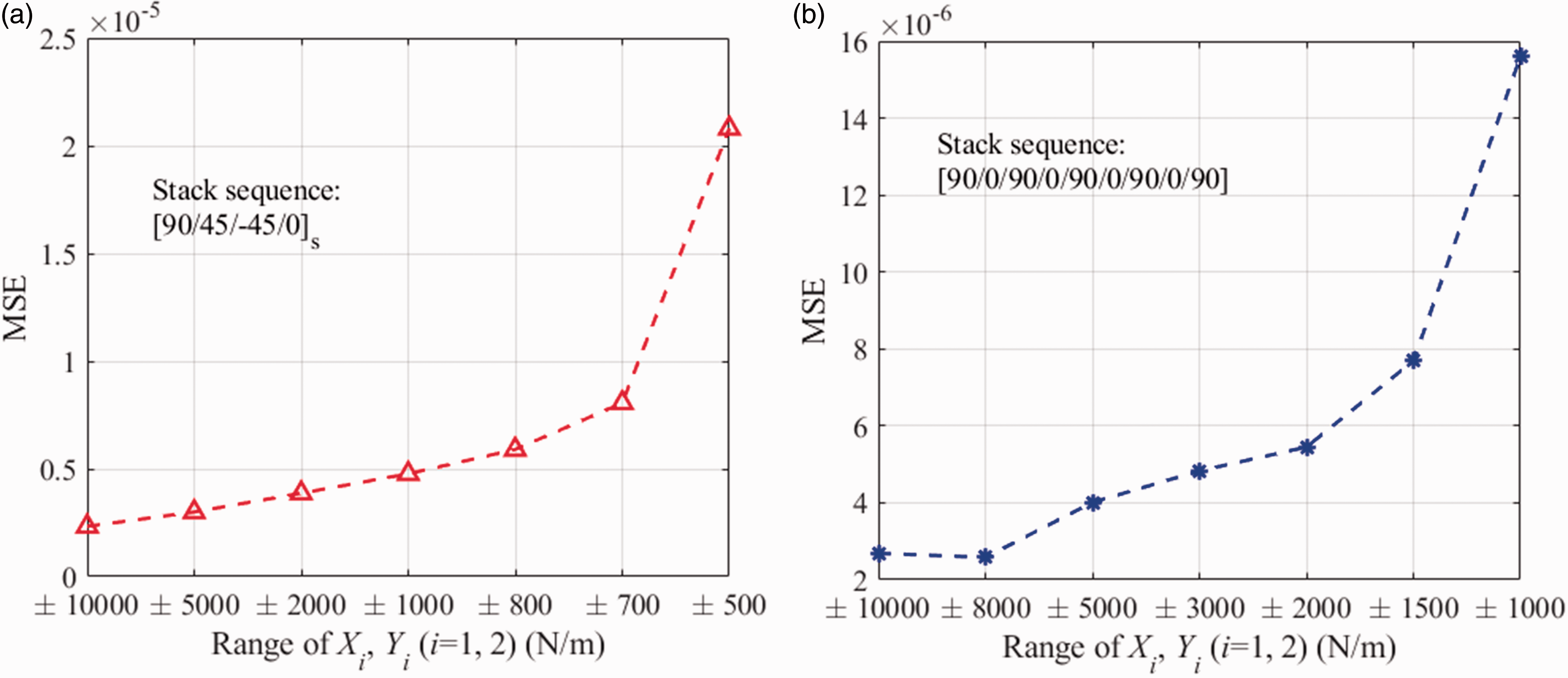
As shown in the figures, when the range of the actuation forces is reduced, the error between the optimised deformed shape and the target shape will generally increase. The results indicate that for a skin with constant stiffness, high actuation forces allow the target shape to reached more closely. Note that the mean squared error is only a geometry index and an aerodynamic evaluation is necessary to determine whether the shape error is acceptable. In this case, an error less than 5 × 10⁻⁶ is acceptable for the baseline and target shapes.
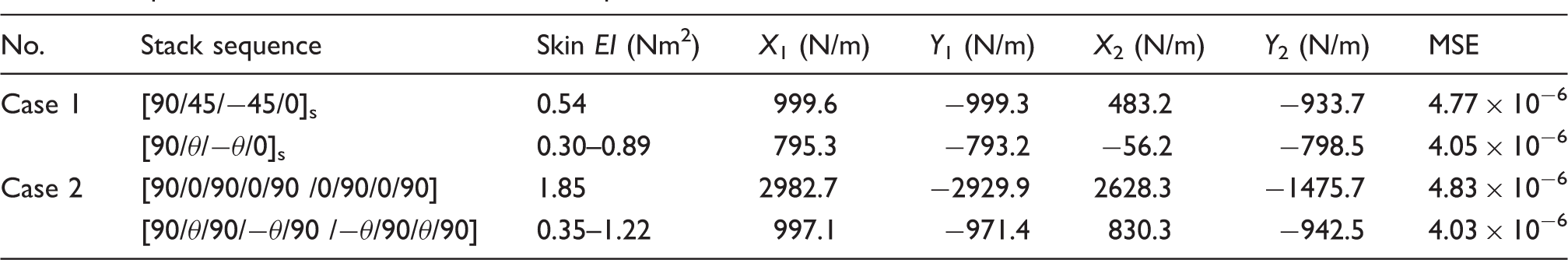
Optimised actuation forces and mean squared errors with constant and variable stiffness skins.
Results using variable stiffness skin
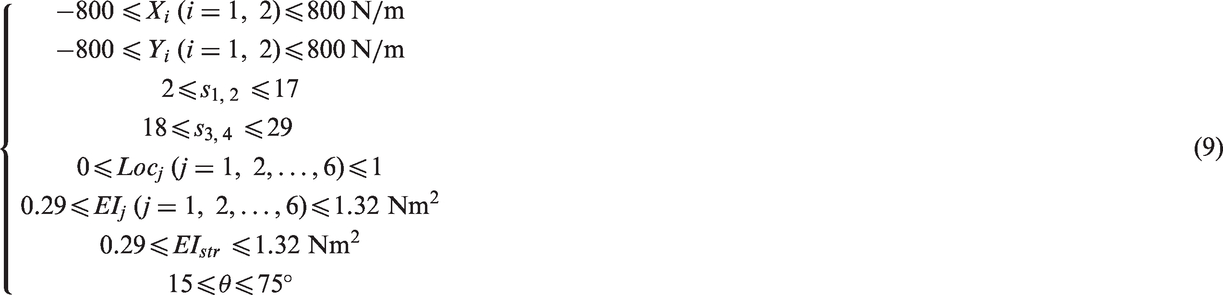
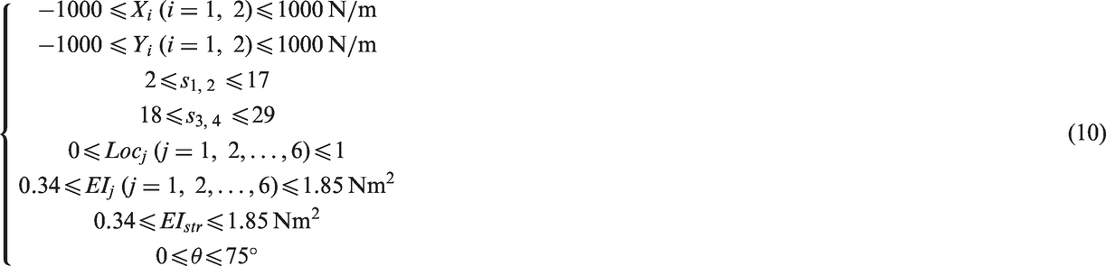
Variable lamina angles are introduced into the stack sequences of the two test cases, while the lamination is still kept symmetrical and balanced. For Case 1, the variable stack sequence is denoted as [90/θ/−θ/0]s. With the given lamina angle range, the range of the skin stiffness can be estimated to ensure that the optimised skin stiffness from the first level can be matched in the second level. The range of the actuation forces is initially set to be the same as used for the constant stiffness skin (±1000 N/m), and then reduced gradually until the error is larger than 5 × 10⁻⁶. Stringers 1 and 2 are assumed to be on the upper surface of the aerofoil, and Stringers 3 and 4 on the lower surface; hence the range of the variable si (i = 1, 2, 3, 4) omits the first and last node of the leading edge skin.
The detailed variable range for Case 1 is given by
The optimisation results from the first level are shown in Figure 6. It can be seen that the target shape is very well reached except in a small area of the lower surface. The leading edge skin tends to have high stiffness on the upper surface, and the smallest stiffness can be found around the tip of the leading edge.
First level optimisation results employing variable stiffness skin for Case 1: (a) optimised deformed shape; (b) skin stiffness distribution.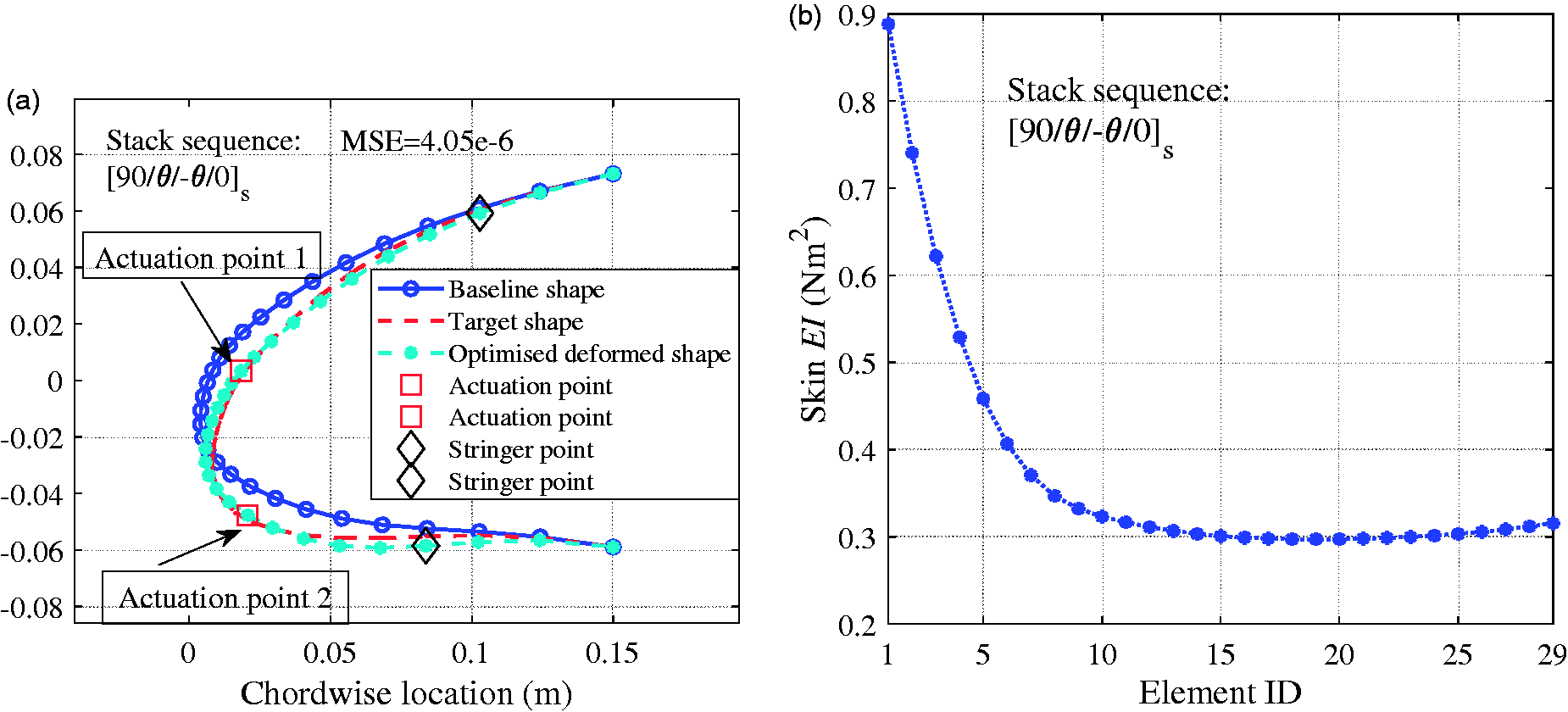
The optimised stiffness distribution is within the range of the skin stiffness, which guarantees the stiffness distribution is reasonable for the specific stack sequence and lamina angle range. The optimised actuation forces and the mean squared error are summarised in Table 3. Compared to the results for the constant stiffness skin, the required actuation forces of the variable stiffness skin are reduced significantly while the errors are smaller than those from the constant stiffness skin.
The optimisation results from the second level are shown in Figure 7. The lamina angle varies along the leading edge and tends to have the maximum angle around the tip of the leading edge, which corresponds to the smallest skin stiffness. The failure index is found to be less than 1 while the elements adjacent to the actuation points (s2 = 11 and s3 = 22) have larger failure indexes than the other elements, which indicates the effect of the actuation points. The largest failure index is caused by the inter-fibre failure, which occurs at the layer that has the largest distance to the mid-plane of the composite.
Second level optimisation results employing variable stiffness skin for Case 1: (a) optimised lamina angle θ; (b) failure index.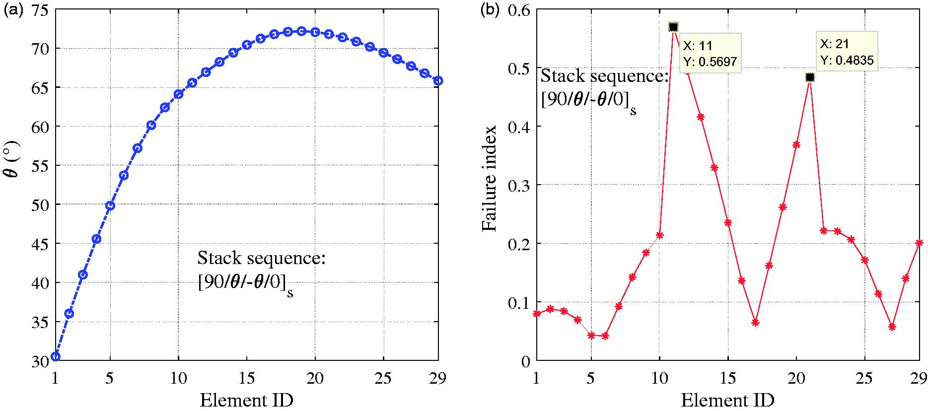
The same approach is applied for Case 2, where the stack sequence becomes [90/θ/90/−θ/90/−θ/90/θ/90].
The variable range for Case 2 is given by
The optimisation results from the first level are shown in Figure 8. The target shape is still well reached and the main error occurs on the lower surface. Only one-third of the actuation force for the constant stiffness skin is required to provide an even smaller shape error, compared to the results for the constant stiffness skin.
First level optimisation results employing variable stiffness skin for Case 2: (a) optimised deformed shape; (b) skin stiffness distribution.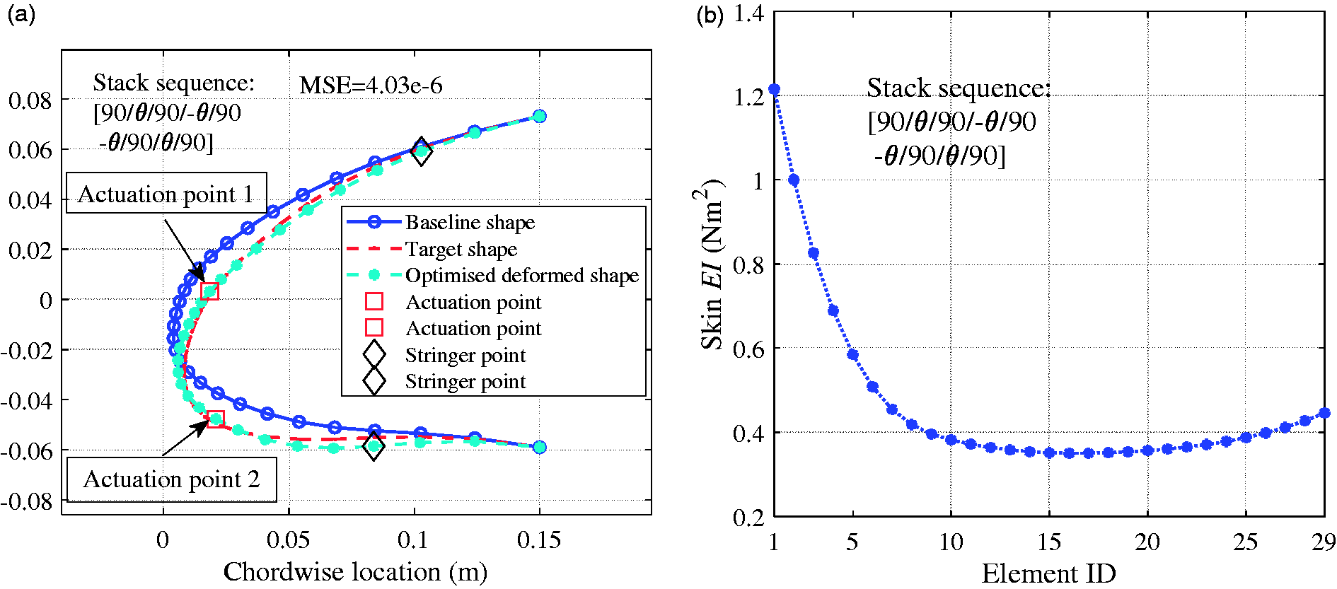
The optimisation results from the second level of Case 2 are shown in Figure 9. Similar results to Case 1 for the lamina angle and failure index are found. The largest lamina angle is found around the tip of the leading edge, and the failure index remains less than 1. The high failure index occurs adjacent to the actuation points (s2 = 11 and s3 = 22). The largest failure index is also caused by inter-fibre fracture.
Second level optimisation results employing variable stiffness skin for Case 2: (a) optimised lamina angle θ; (b) failure index.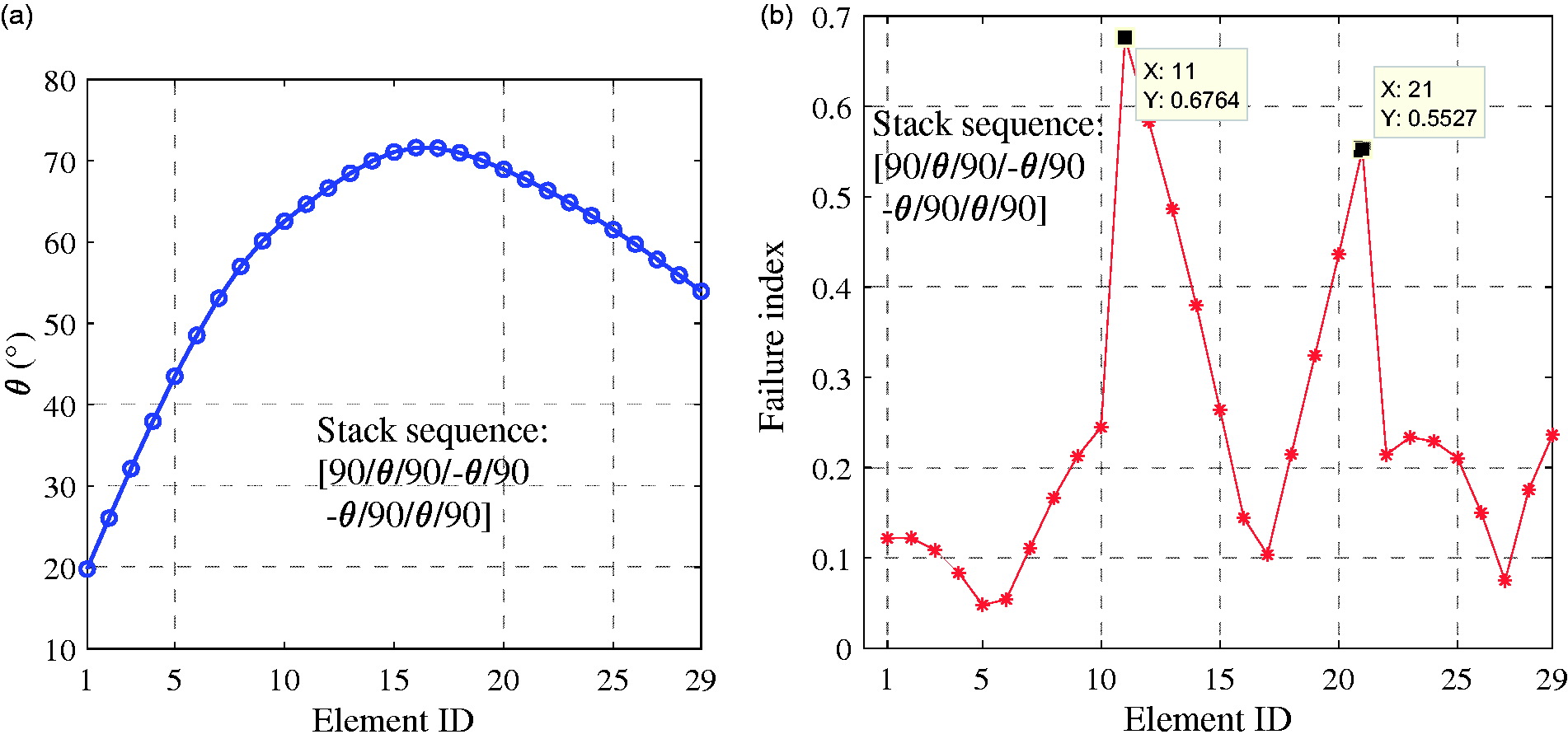
Post-optimisation aero-structure analysis
The optimised results indicate that the leading edge skin made with variable lamina angles has the potential to reach the target shape more closely with reduced actuation forces. The post-optimisation aero-structure analysis is performed to check whether the optimised leading edge skin has a sufficiently small deformation under the aerodynamic loads. The optimisation scheme in an earlier section decouples the aerodynamic analysis and the structural analysis. Thus, the aerodynamic loads applied onto the structural model remain unchanged, and correspond to the load case of the target shape. This approach has the inherent assumption that the differences of the aerodynamic loads on the optimised leading shape and the target shape are negligible. In reality, the optimised leading edge shape is not exactly the same as the target shape, which will lead to different aerodynamic loads on the leading edge skin. This difference will cause the shape of the leading edge to change, which can cause a change in the aerodynamic loads. The post-optimisation analysis is then needed to monitor the change of the leading edge shape.
In the aero-structure analysis, the actuation points are fixed to simulate the self-locking capability of the actuation mechanism. The actuation mechanism is assumed to transfer the aerodynamic loads onto the main spar of the wing and be rigid enough compared to the leading edge skin, which can lock the position of the actuation points. The optimised leading shape obtained in the previous section are imported into the aerodynamic module, which is performed in Ansys Fluent®,
27
and the corresponding aerodynamic loads are returned to the structural model, which updates the shape of the leading edge. The updated shape is then used for the aerodynamic analysis to generate the aerodynamic loads on the leading edge, which will again update the leading edge shape in the structural analysis. Five iterations between the aerodynamic and structural analysis are performed. The results of the post-optimisation check are shown in Figure 10 for Cases 1 and 2 from the previous section. In both cases, the mean squared error (MSE) between the deformed shapes during the current and previous iterations is reduced very quickly. The MSE during the second iteration has decreased to be smaller than 10−10, while the MSE between the optimised deformed shape and the target shape is of the order of 10−6. The maximum node displacement of the leading edge skin is also very small compared to the size of the chord.
Post-optimisation aero-structure analysis for (a) Case 1 and (b) Case 2: MSE between the deformed shapes of the current and previous iteration (left y-axis), and the maximum node displacement (right y-axis).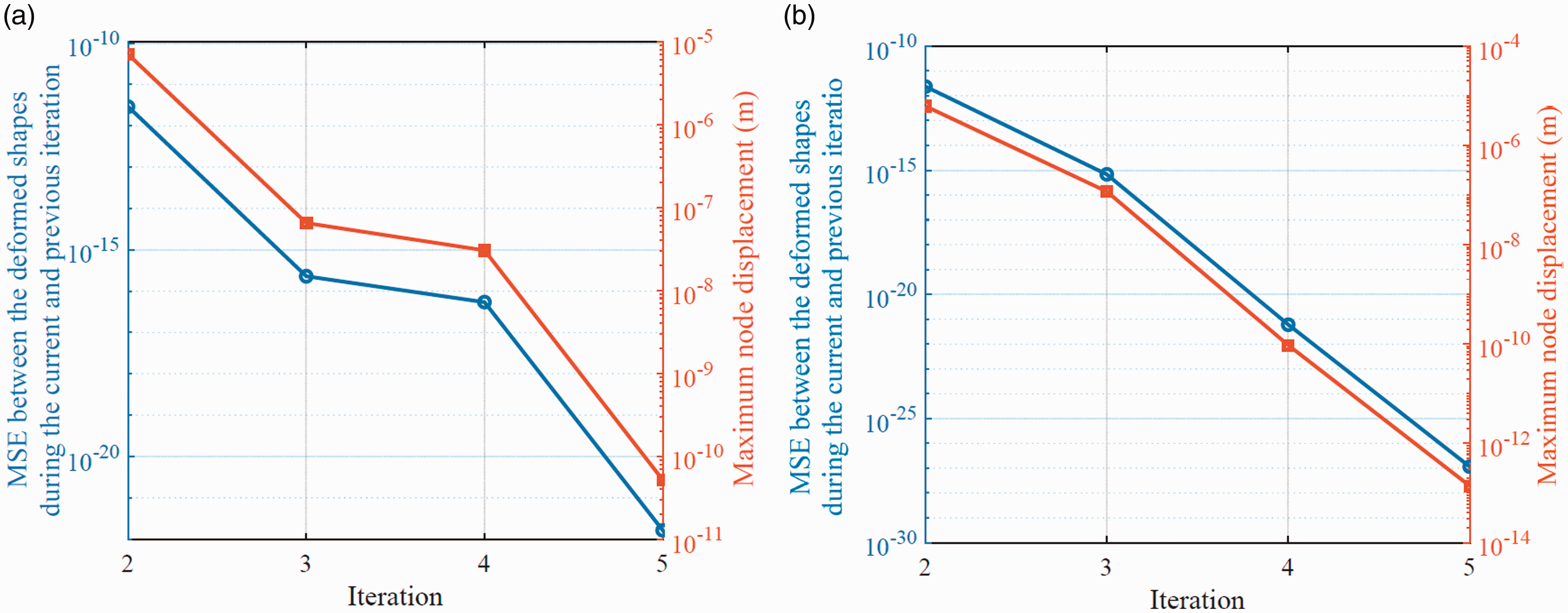
The analysis results indicate that the optimised leading edge shape is very close to the target shape, and the optimised leading edge is able to sustain the aerodynamic loads with the help of the locked actuation points.
Conclusions
In this paper, a conceptual-level optimisation scheme is established to analyse a spatially-variable stiffness skin of a morphing leading edge. The influence of the variable stiffness skin is investigated, which indicates the capability of reducing the actuation forces. Optimisation results from the test cases are shown. The results for the constant stiffness skin using straight fibre composites are obtained initially to compare to the results for a variable stiffness skin with variable lamina angles. A significant reduction of the actuation forces can be found if the lamina angles are varied in the test cases. A failure analysis is performed for the composites, which can be used to find the index to validate the feasibility of the design and also suggests that large failure indexes would occur in the area adjacent to the actuation points. The post-optimisation aero-structure analysis is also performed to verify the deformation of the leading edge skin.
The results show two contributions of the proposed analysis method:
When the stack sequence of the leading edge skin is obtained in the second level, the corresponding failure index can be used to verify the feasibility of the shape change at the conceptual level study. The potential benefit of reducing actuation forces is also highlighted in the test cases, as the reduced actuation forces can lead to reduced weight and thus an improvement of performance.
The proposed method may also be applied to other morphing leading edge designs if the baseline and target shapes are known. Since only 2D models are considered in the paper, some detailed designs, such as the stringer and the spanwise layout, are not taken into account. Future work will involve the detailed modelling of 3D cases and the manufacturing method of the variable stiffness composite will also be considered.
Declaration of Conflicting Interests
The author(s) declared no potential conflicts of interest with respect to the research, authorship, and/or publication of this article.
Funding
The author(s) disclosed receipt of the following financial support for the research, authorship, and/or publication of this article: This study was supported by the EU Clean Sky project OPTIMOrph (Grant Agreement 755068).