
Abstract
Railway bogies are fundamental to vehicle stability, ride quality, and dynamic performance, with the primary suspension system playing a crucial role in isolating high-frequency vibrations and maintaining consistent wheel-rail contact and vehicle stability. This paper presents a novel resilient biasing device, protected under international patent WO/2025/027292, which integrates the functions of a spring and axlebox into a single component, thereby simplifying the architecture of the primary suspension system. The mechanical performance of this patented concept was assessed through finite element modelling, analytical methods and experimental validation to predict stiffness characteristics, induced stresses, and vibration transmissibility. Two design configurations, a single-loop and a multiple-loop configurations, were investigated for a reference vehicle comprising a 40-tonne carbody and a 5-tonne bogie against real-world load conditions. Both designs were found to deliver the required stiffness, maintain stress levels below the material yield limit, and provide effective vibration isolation. The single-loop design demonstrated advantages in terms of reduced mass, improved vibration isolation, and manufacturing cost-effectiveness. In contrast, the multiple-loop design offered lower stress levels, making it more suitable for applications involving higher payloads. The resilient biasing device can be geometrically and materially optimised to meet specific performance requirements, offering a versatile solution for primary suspension systems in rail vehicles. Moreover, the concept holds promise for broader application in the automotive and heavy vehicle sectors, as well as in other industries requiring integrated suspension and vibration isolation systems tailored to specific operational demands.
Keywords
Introduction
Railways play a vital role in the transportation of passengers, offering a sustainable, reliable, and safe mode of travel. As demand for rail transport continues to grow, ongoing innovation in vehicle systems is essential. Among the most critical components of a railway vehicle are the bogies, which ensure stability, ride comfort, and effective load distribution. They absorb shocks and facilitate smooth navigation through curves and track irregularities. Within the bogie, the primary suspension system is fundamental to safe and efficient operation. It isolates the vehicle body from high-frequency vibrations induced by the track, maintains consistent wheel-rail contact, and manages dynamic forces between the bogie and the track to provide stability. In contrast, the secondary suspension system filters low-frequency vibrations to enhance passenger comfort and controls car body motions. 1 The design of suspension systems is typically guided by advanced engineering tools such as multibody dynamic simulations, finite element analysis, and optimisation algorithms, all aligned with international standards like EN 14363. 2 The selection of spring elements is crucial, as it directly influences performance, durability, and maintenance. Steel coil springs, known for their linear stiffness, are widely used in both primary and secondary suspensions. Rubber and elastomer springs, valued for their viscoelastic damping and low maintenance, are often configured as chevron or conical springs. Composite springs, made from fibre-reinforced polymers, offer weight savings and corrosion resistance, though their adoption remains limited due to concerns over cost and long-term durability. 3 Iwnicki et al. 4 reviewed the evolution of primary suspension systems in freight bogies, highlighting the transition from early leaf spring designs, providing vertical compliance and limited lateral and longitudinal movement, to more advanced systems. These included Lenoir links, which introduced load-dependent damping through angled mechanical linkages and friction surfaces, and modern coil spring systems often paired with hydraulic or friction dampers. Rubber-based elements, such as toroidal springs, have also been adopted for their combined elasticity and damping. More recently, magnetorheological dampers have been shown to reduce vertical vibrations and improve ride quality, 5 while inerter-based systems have demonstrated benefits in both passenger comfort and track wear reduction. 6
Suspension performance is assessed using key indicators defined in standards such as EN 14363, EN 13749, UIC 518, and ISO 2631-1.2,7–9 A human-seat model can be combined with a car-body model to predict the human response at different positions in the railcar. 10 Locomotive operators can be exposed to mechanical shocks, especially during run-in and run-out processes for freight. Suspension stiffness (vertical, lateral, longitudinal, and yaw) must be optimised to balance comfort, safety, and dynamic performance. For example, primary vertical stiffness for passenger vehicles has been used in the vicinity of 1 MN/m,11–13 with lower values for freight wagons and higher values for high-speed or heavy locomotives. 14 Lateral stiffness is typically balanced to deliver a trade-off between stability and improved curving behaviour, while longitudinal stiffness is designed to manage traction and braking forces. 15 Yaw stiffness of the bogie is influenced by the lateral and longitudinal stiffnesses of the primary suspension system, as these govern the bogie’s resistance to rotational motion during curving and hunting dynamics. The yaw stiffness varies by vehicle type, with higher values in high-speed trains and locomotives. 16 The yaw stiffness strikes a balance between curving agility and hunting stability, a key consideration in high-speed rail dynamics. 11 These stiffness parameters are not fixed by ratio but are tuned through performance trade-offs and validated using multibody simulations and kinematic compliance testing. Vibrations in railway systems arise from geometric and structural irregularities, exciting a wide range of frequencies depending on speed, wheel size, and track conditions. Kouroussis et al. 17 identified excitation frequencies from 1 Hz to over 10,000 Hz, with low frequencies (<10 Hz) linked to large-scale vehicle dynamics, mid frequencies (10-100 Hz) to axle and wheel passage, and high frequencies (>30 Hz) to wheel-rail interaction and structural resonances. To isolate high-frequency excitations, the primary suspension is typically designed with a vertical natural frequency of 8–15 Hz.18,19 The secondary suspension, with a natural frequency around 1 Hz, targets low-frequency isolation and aligns with human sensitivity to vertical vibrations in the 4-8 Hz range, thereby enhancing passenger comfort.9,20,21
Railway suspension systems represent a sophisticated integration of mechanical design, materials science, and modelling. As the railway industry continues to evolve, this paper aims to present a new design concept where an axle and bearing are integrated into a recently invented resilient biasing device, a novel mechanical spring applied to a primary suspension system. The resilient biasing device, invented by Afazov and Mansfield et al., 22 features a unique configuration comprising two mirrored spirals. This geometry enables the device to deliver multi-directional stiffness and effective vibration isolation, offering a promising alternative to conventional spring technologies. 23 To explore the feasibility and performance of this innovation, the proposed suspension concept is first introduced in detail. Finite element analysis (FEA) and a predictive model for vibration transmissibility were developed to assess both the static and dynamic characteristics of the design. To validate the accuracy of the vibration transmissibility model, a scaled-down prototype was fabricated and tested using a shaker system. The experimental results were then compared with the model predictions to establish confidence in the simulation approach. These validated models were subsequently employed to predict stress distributions, stiffness characteristics, and vibration responses under representative railway vehicle and realistic loading conditions.
While conventional primary suspension systems rely on coil springs, rubber elements, or hydraulic dampers, these solutions typically separate the spring and axlebox functions, resulting in increased complexity and maintenance. The proposed resilient biasing device integrates these functions into a single component, offering a simplified architecture with multi-directional stiffness and vibration isolation. Unlike magnetorheological or inerter-based systems, which require active control or additional components, the resilient biasing device achieves passive isolation through geometric design, potentially reducing cost and improving reliability.
Design concept
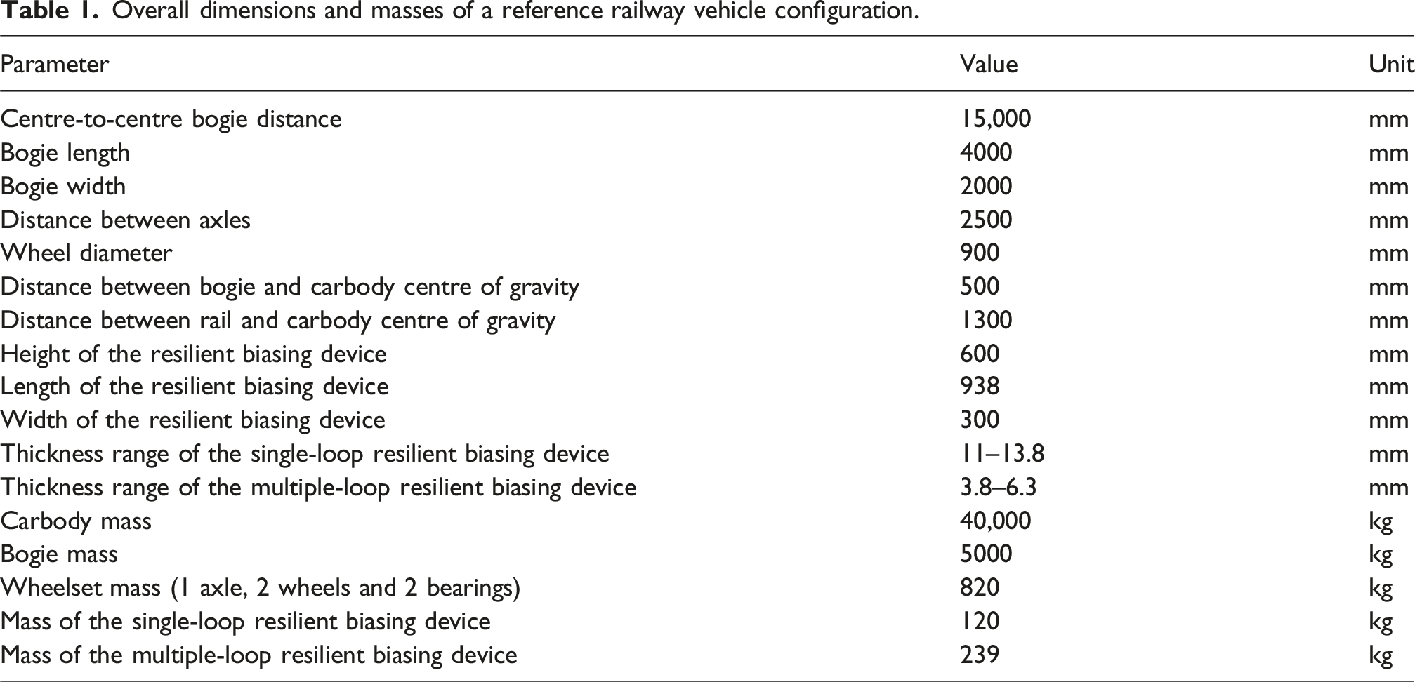
Overall dimensions and masses of a reference railway vehicle configuration.
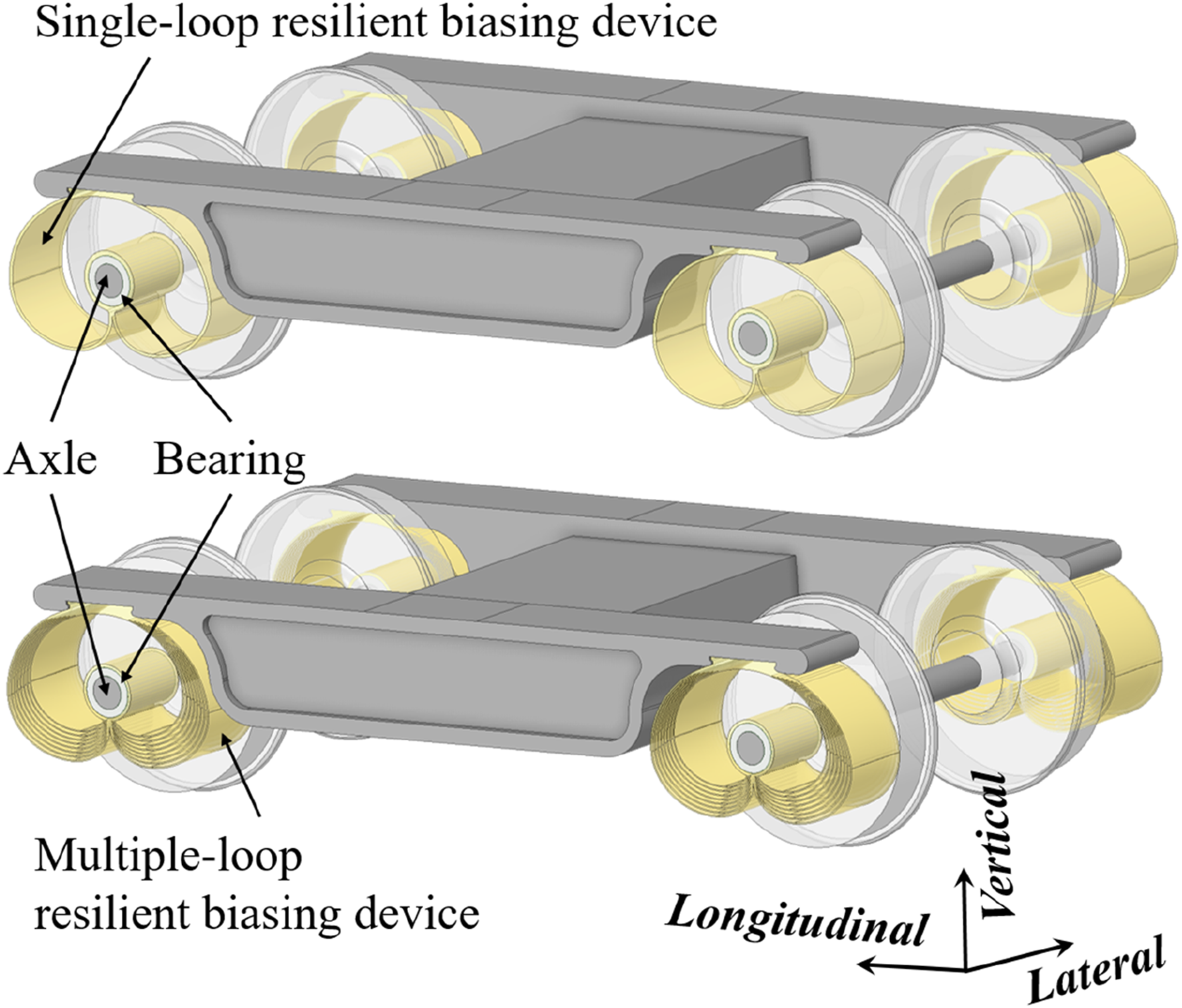
Conceptual design of a primary suspension system featuring single and multi-loop resilient biasing devices.
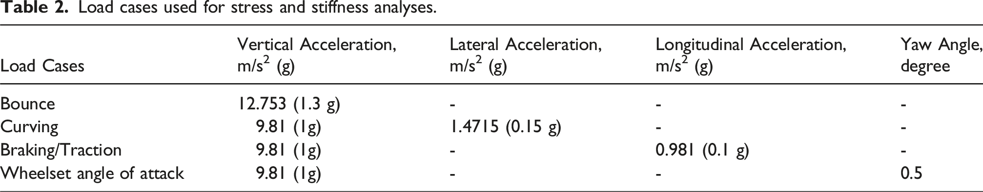
Load cases used for stress and stiffness analyses.
Modelling approach
Finite element models
The design illustrated in Figure 1 was used as the basis for developing finite element models. The bogie frame and wheelset components were meshed using linear 8-node hexahedral elements with a relatively coarse mesh. This approach was adopted as these components are not the primary focus of the study; a lower mesh density is sufficient to capture their mass and stiffness characteristics representatively. In contrast, the two resilient biasing devices were meshed using 20-node quadratic hexahedral elements to ensure higher fidelity in capturing their mechanical behaviour. The resulting meshes for the single-loop and multiple-lop design configurations are shown in Figures 2(a) and 2(b) respectively. Additionally, half of the carbody mass (20 tonnes) was represented by a point mass applied at the top of the bogie frame. The resilient biasing devices were modelled using 55SiCrV spring steel, which has a reported yield strength exceeding 1800 MPa.
24
The material properties used for 55SiCrV are Youngs modulus of 207 GPa, Poisson ration of 0.3 and density of 7850 kg/m3. All components were modelled as linear elastic using standard steel properties. Finite element models: (a) mesh of a single-loop design configuration; (b) mesh of a multi-loop design configuration; (c) application of bounce load case; (d) application of curving load case; (e) application of braking/traction load case; (f) application of angle of attack load case.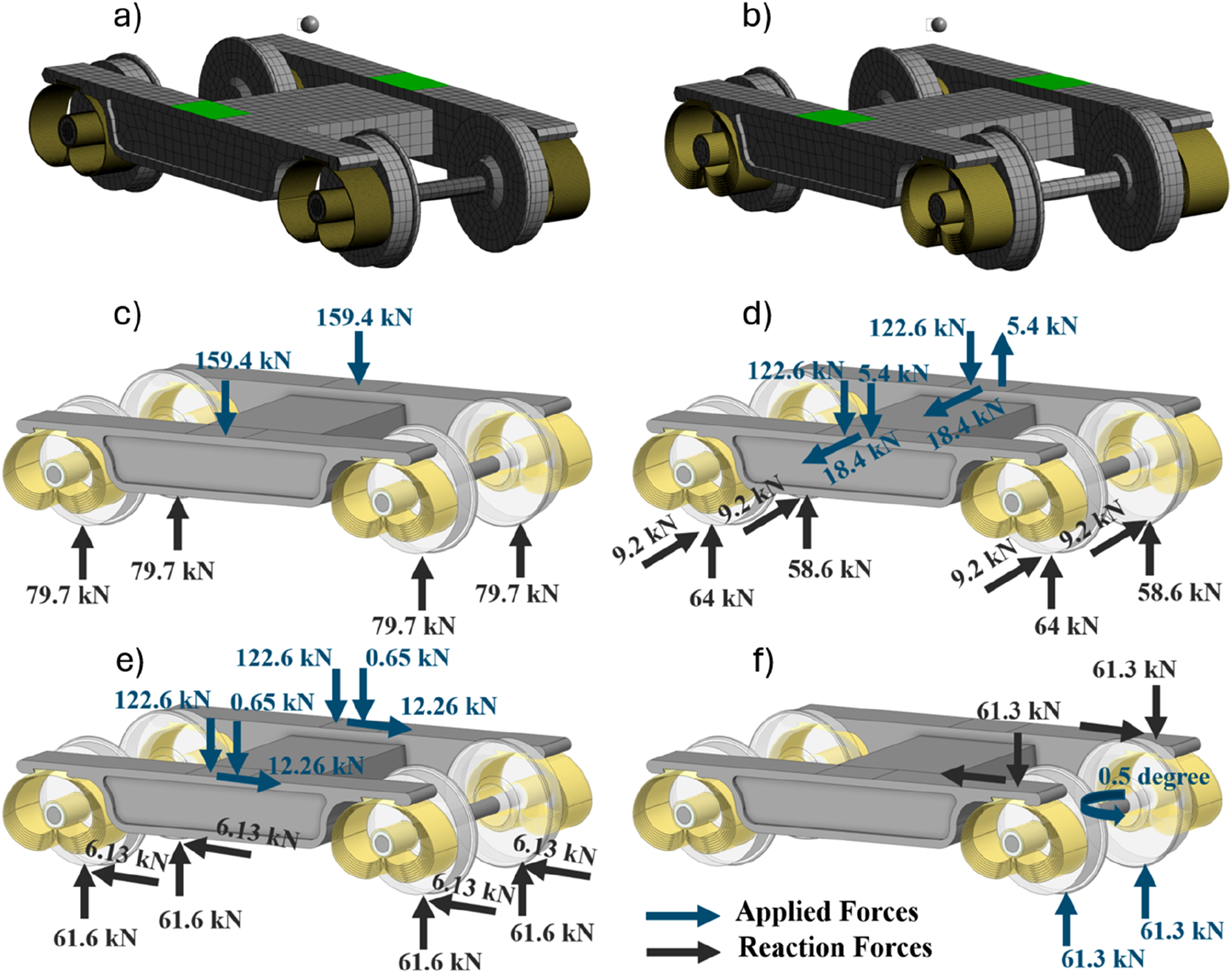
Both static structural and modal analyses were conducted. For the modal analysis, only weak springs were applied to the mesh to simulate free vibration conditions, with no additional boundary constraints. The weak spring method stabilises under-constrained systems by introducing low-stiffness springs, typically defined as 1.0 × 10⁻⁶ times the average diagonal stiffness, ensuring minimal influence on the overall solution accuracy. This setup enabled the extraction of natural frequencies and mode shapes within the 0–100 Hz range. The results of the modal analysis were subsequently used in the vibration transmissibility model presented in Section 3.2. The static structural analyses were performed to predict stiffness and stress responses under the loading conditions defined in Table 2. Figures 2(c)–(f) illustrate the applied loads and reaction forces at the wheel locations, where zero displacement boundary conditions were imposed in all directions. For the vertical bounce load case (see Figure 2(c)), the combined mass of the bogie and half the carbody was distributed across the centres of the two side beams of the bogie frame by applying a force representing an acceleration of 1.3 g. In the curving scenario (see Figure 2(d)), in addition to the vertical forces from the payload, lateral forces corresponding to 0.15 g acceleration were applied. Additionally, a moment was introduced from the carbody centre of mass to the bogie frame, resulting in increased vertical force on one side and a reduction on the other. In the braking/traction load case (see Figure 2(e)), the vertical gravitational force was increased due to the moment generated by the carbody, whose centre of mass is located 500 mm above the bogie. This moment is reacted at each bogie, spaced 15 m apart. To model the angle of attack (see Figure 2(f)), the top surfaces of the bogie frame were fixed, and vertical forces were applied at the wheels. A remote displacement was imposed on the axle to induce a rotational displacement of 0.5°. This arrangement represents the wheelset motion during curving, allowing the reaction forces at the fixed boundaries to be used in calculating the yaw stiffness and predicting stress levels. The stiffnesses for the remaining three load cases were determined based on the predicted directional displacements under the respective directional loading conditions.
Vibration transmissibility model
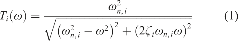
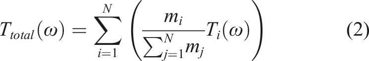
A vibration transmissibility model is developed for the resilient biasing device to quantify the extent of oscillatory energy transmitted from the wheel to the bogie frame. The transmissibility function is derived for a multi-degree-of-freedom system subjected to base excitation. Each vibrational mode is treated as an independent single-degree-of-freedom system, characterised by its natural frequency, damping ratio, and effective mass. The overall system response is obtained by superimposing the contributions of the individual modes. The vibration transmissibility is given by
26
:
Validation approach
The proposed model was validated using a scaled-down prototype, constructed at a scaling factor of 1:0.0625 relative to the full-scale design. The scaling factor was selected based on the operational and safety limitations of the electrodynamic shaker system used for the experimental testing. This prototype facilitated both physical fabrication and experimental testing, enabling validation of the vibration transmissibility model, which was subsequently applied to the analysis of the full-scale designs. For the prototype, the resilient biasing devices were fabricated via 3D printing using PETG filament to achieve a target natural frequency of approximately 10 Hz, which aligns with the operational frequency range of railway primary suspensions. While PETG does not replicate the mechanical properties of spring steel, the validation focused on verifying the vibration transmissibility model and modal behaviour. Also, the validation experiment focused on the single-loop design to confirm the accuracy of the vibration transmissibility model. The validated model was then applied to both design configurations at full scale using spring steel material properties. The bogie frame was machined from Delrin polymer, while the wheels and axle were manufactured by turning aluminium and stainless steel, respectively. Commercially available needle bearings were integrated into the resilient biasing devices. The assembled prototype was mounted onto an electrodynamic vibration testing system (LDS V780, manufactured by Brüel & Kjær). An aluminium plate was fixed to the shaker, with a control accelerometer (Brüel & Kjær 4533-B, sensitivity: 9.81 mV/g) attached centrally on the plate. The prototype was clamped at the axle locations, and a 10 kg mass was applied to simulate operational loading (see Figure 3(a)). Two accelerometers were used: one positioned at the interface between the axle and the resilient biasing device, and the other on the bogie frame directly above the resilient biasing device. A sinusoidal excitation with an amplitude of 0.1 g was applied across a frequency range of 3–15 Hz, with 1 Hz increments. To more accurately identify the peak natural frequency, a finer increment of 0.1 Hz was used between 10 and 11 Hz. The acceleration amplitude was increased to 0.25 g for the 15–40 Hz range, and to 0.5 g for the 40–100 Hz range. The voltage output from each accelerometer was recorded, as illustrated in Figure 3(a). Vibration transmissibility was calculated as the ratio between the voltage range measured at the bogie frame (ΔVframe) and that measured at the axle (ΔVaxle). Illustration of: (a) experimental set-up scaled-down prototype and measured signal for obtaining the vibration transmissibility; (b) finite element model for modal analysis; (c) comparison of experimental and predicted vibration transmissibility.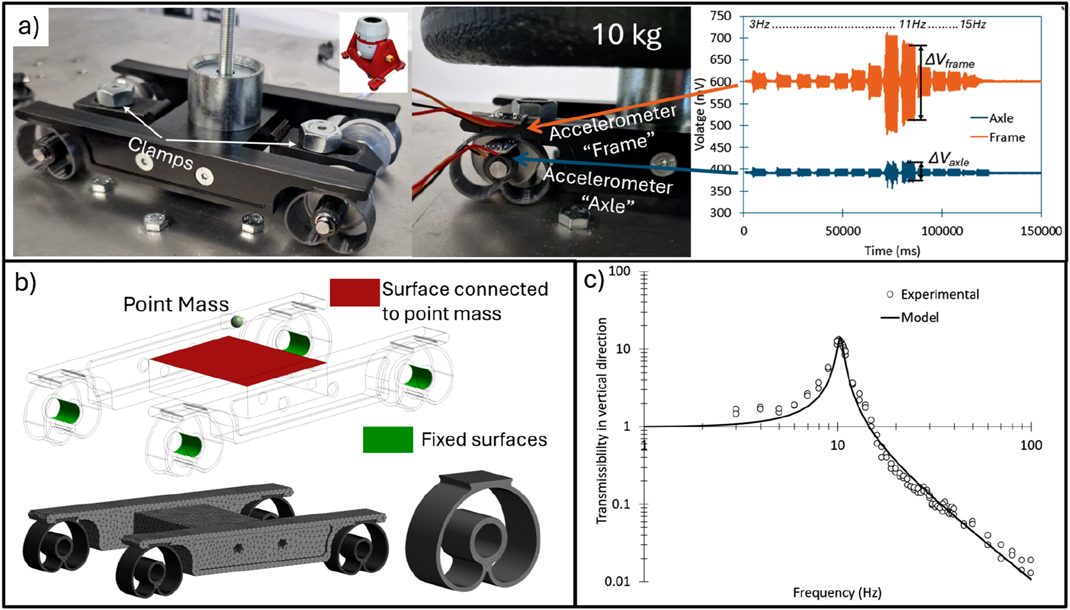
A finite element model replicating the experimental setup was developed in ANSYS (see Figure 3(b)). The resilient biasing devices were modelled as linear elastic components, with PETG material properties assigned: Young’s modulus of 2.05 GPa and Poisson’s ratio of 0.36. The bogie frame was modelled using a Young’s modulus of 3.0 GPa and a Poisson’s ratio of 0.38. The actual mass of the frame and attachments was 980 g, accounted for in the model via adjusted material density. The 10 kg applied mass was modelled as a point mass located at the centre of the frame. The clamped axle condition was represented using fixed boundary conditions at the bearing and the resilient biasing device interface, thereby eliminating the need for detailed modelling of the clamping mechanism. Modal analyses were performed to predict natural frequencies and effective masses within the frequency range of 0–100 Hz. Four vibration modes were found in this range: Mode 1 at 5.52 Hz, Mode 2 at 7.34 Hz, Mode 3 at 10.4 Hz, and Mode 4 at 85.4 Hz. The dominant vertical mode was Mode 3, with an associated effective modal mass of 99.8%. A uniform damping ratio of 0.035 was assumed for all modes. These modal parameters were used as input to the proposed transmissibility model described in Section 3.2. A comparison between the modelled and experimentally measured transmissibility is shown in Figure 3(c). The close agreement between the predictions and experimental data supports the validity of the proposed modelling approach.
Results and discussion
This section presents the analysis of three key performance indicators for both design configurations. The first one is stiffness, predicted based on the applied loads and the resulting displacements from the finite element models. Figure 4 presents the force–displacement relationships predicted by the finite element analysis for four loading scenarios: bounce (vertical), curving (lateral), traction/braking (longitudinal), and yaw moment versus rotational displacement for the angle of attach load case. Stiffness values were extracted at the maximum applied load, and their corresponding linear fits are also illustrated in Figure 4. With the exception of the vertical direction, particularly in the multiple-loop design configuration, the stiffness response can generally be considered linear. In the vertical case, a reduction in stiffness of approximately 5% was observed with increasing load. Nevertheless, within the operational range of 0.7 g to 1.3 g, the stiffness remains sufficiently linear, which is critical for ensuring consistent dynamic performance. Precited force-displacement relationships and obtained stiffness values for the: (a) bounce load case; (b) Curving load case; (c) braking/traction load case; (d) angle of attack load case.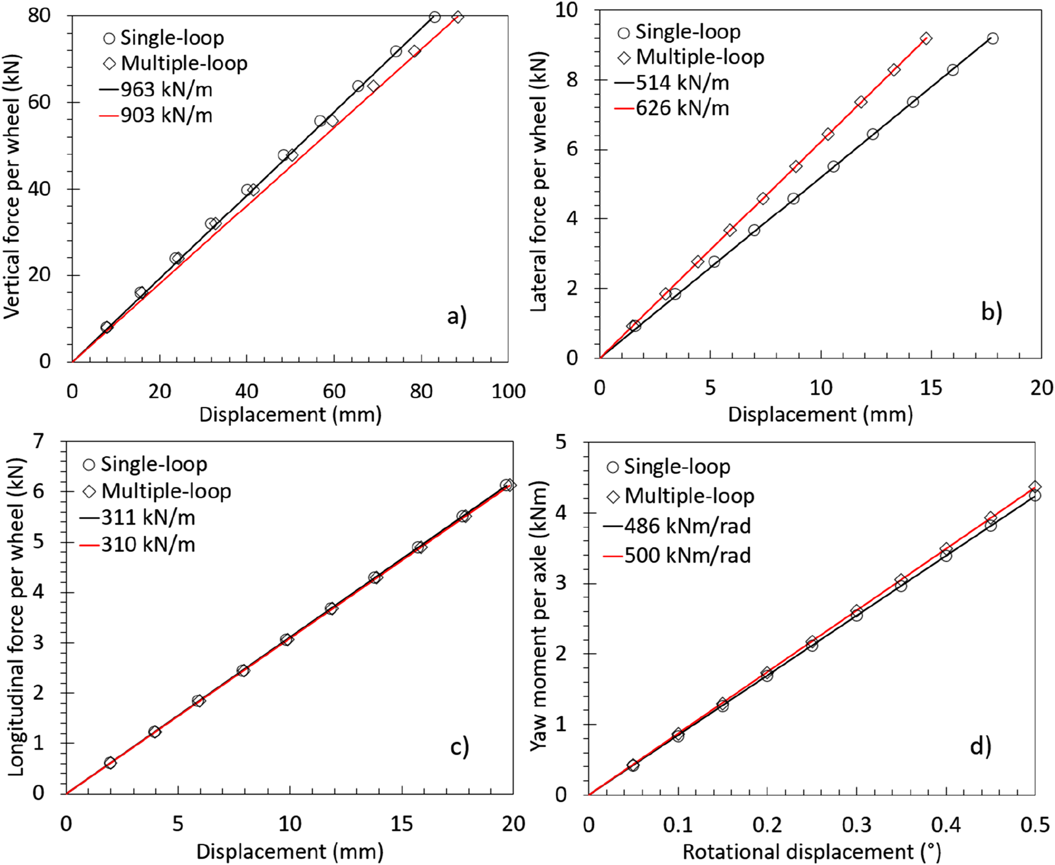
The vertical stiffness for both the single-loop and multiple-loop designs was below 1 MN/m. The lateral stiffness was approximately two-thirds of the vertical stiffness, while the longitudinal stiffness was about one-third. When comparing the two designs, the ratio between vertical and lateral stiffness was lower in the multiple-loop configuration, indicating increased lateral stiffness. The longitudinal stiffness remained similar across both designs. The yaw stiffness values were also close in magnitude with a difference of 2.8%. The lateral and yaw stiffnesses as well as the damping are particularly important for the hunting stability. As a general principle, increased lateral and yaw stiffness enhances vehicle stability and raises the critical speed. However, very high lateral and yaw stiffnesses can lead to increase forces between the rail and the wheel leading to more wear in curve negotiation. Liu et al. 16 reported that vehicles with a yaw stiffness of 2.65 MNm/rad have critical speeds around 250 km/h, while vehicles with a lower yaw stiffness of 0.15 MNm/rad exhibits a significantly reduced critical speed below 60 km/h. The predicted yaw stiffness in the present study lies within this range. However, the design can be tailored to adjust yaw stiffness, enabling the vehicle to meet specific critical speed requirements. Qu et al. 15 demonstrated that reducing primary yaw stiffness from 40 MNm/rad to 1.14 MNm/rad significantly reduces wheel-rail surface damage in curves. In comparison, both the single-loop and multiple-loop design configurations achieve a yaw stiffness of approximately 0.5 MNm/rad per axle (1 MNm/rad per bogie), closely aligning with the improved yaw stiffness value reported in 15. While lower yaw stiffness can improve curving dynamics by allowing greater rotational compliance of the bogie, it may also reduce hunting stability and increase the risk of lateral instability at higher speeds. To address this trade-off, the resilient biasing device can be geometrically tuned to adjust the yaw stiffness. For instance, increasing the loop thickness or modifying the spiral curvature can raise yaw stiffness while maintaining directional stiffness ratios. A comprehensive vehicle-level performance assessment, incorporating multibody dynamic simulations and carbody acceleration predictions, would be necessary to fully evaluate these interactions. This is identified as a future research direction to optimise future designs of industrial primary suspension systems under realistic railway vehicle requirements and track conditions.
Stress results from finite element analysis.
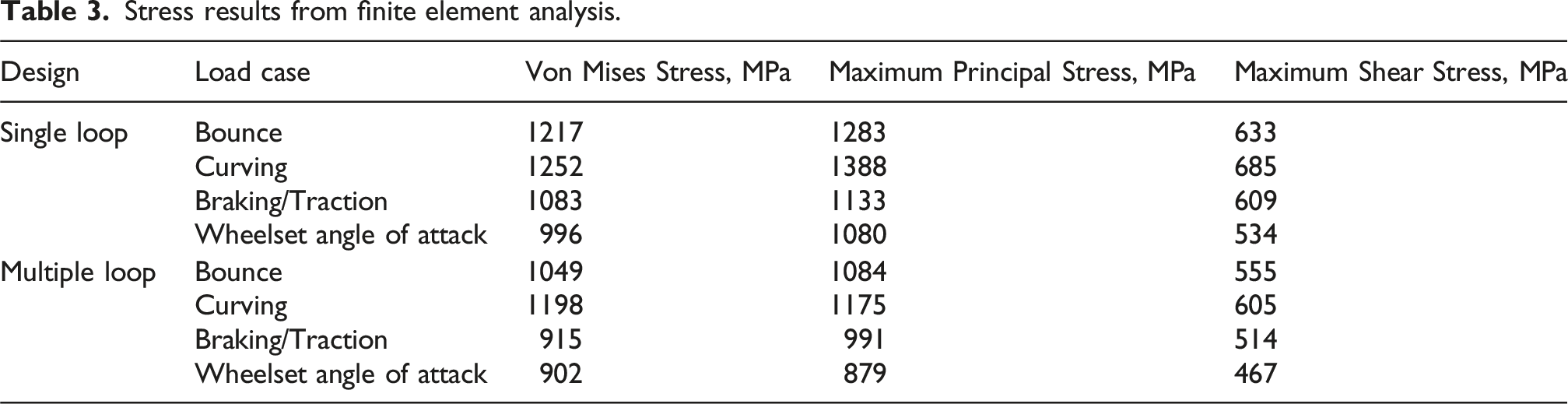
When comparing the two design configurations, the multiple-loop design offers lower stress levels, which is beneficial for durability. However, this comes at the cost of increased mass, approximately twice that of the single-loop design, and greater manufacturing complexity. It is important to note that the multiple-loop design has not been optimised; further reductions in stress could be achieved through optimisation of loop thicknesses and spacing. From a manufacturing perspective, the single-loop design is significantly simpler to produce using methods such as extrusion, conventional machining, water jet cutting, and wire electrical discharge machining. While the multiple-loop design can also be manufactured using water jet cutting and wire electrical discharge machining, the increased number of cuts would raise production time and cost.
Material selection is another critical factor influencing stiffness. For example, using Ti6Al4V, which has a Young’s modulus of approximately 110 GPa (about half that of steel) would result in a corresponding reduction in stiffness. However, since Young’s modulus does not affect stress in the elastic regime, the stress levels would remain unchanged. The yield strength of Ti6Al4V is close to the predicted von Mises stress for the single-loop design, indicating a potential risk of permanent deformation for the investigated vehicle configuration. In contrast, the multiple-loop design may remain within the yield limit. Additionally, Ti6Al4V has nearly half the density of steel, offering significant weight savings. Composite materials reinforced with glass or carbon fibres are also potential candidates, though their higher creep rates compared to spring steels and titanium alloys may be a disadvantage. To prevent fatigue cracking during service, stress ranges must remain below the material’s fatigue limit. The geometry of the resilient biasing device allows for surface finishing and hardening treatments to enhance fatigue strength. For instance, shot peening, commonly used to induce compressive surface stresses in helical springs, can be more precisely applied to the single-loop resilient biasing device, particularly in regions of high maximum principal stresses, such as the inner side of the junction where the two spirals merge. Figure 5 illustrates the locations of maximum principal stress, where fatigue cracks are most likely to initiate for the curving load case. Location and magnitude of predicted maximum principal stresses for a single-loop design in curving, units in MPa.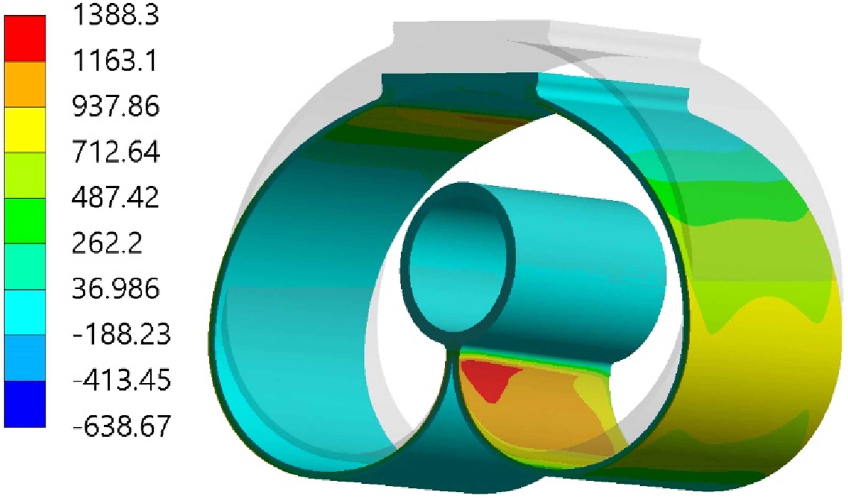
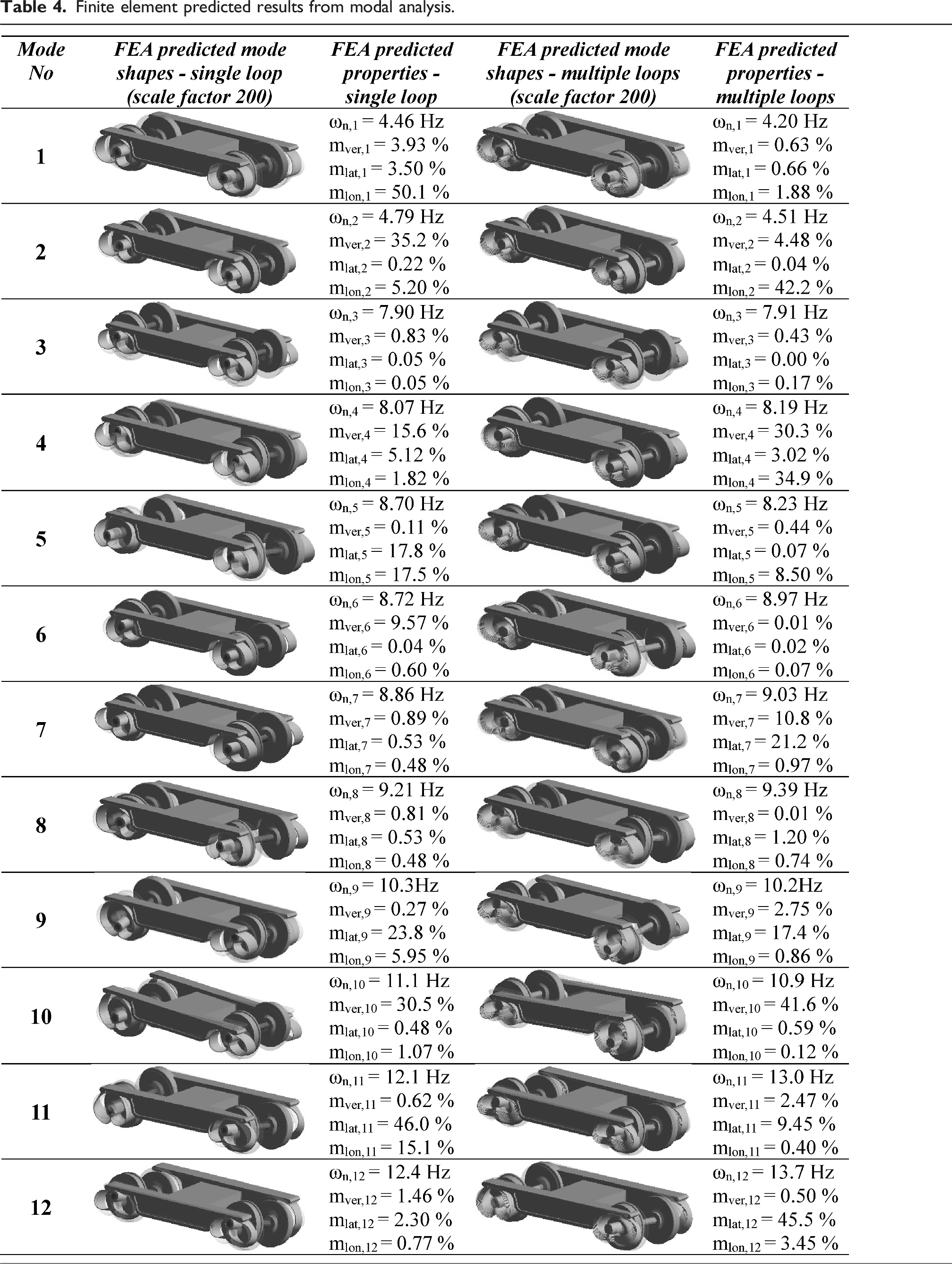
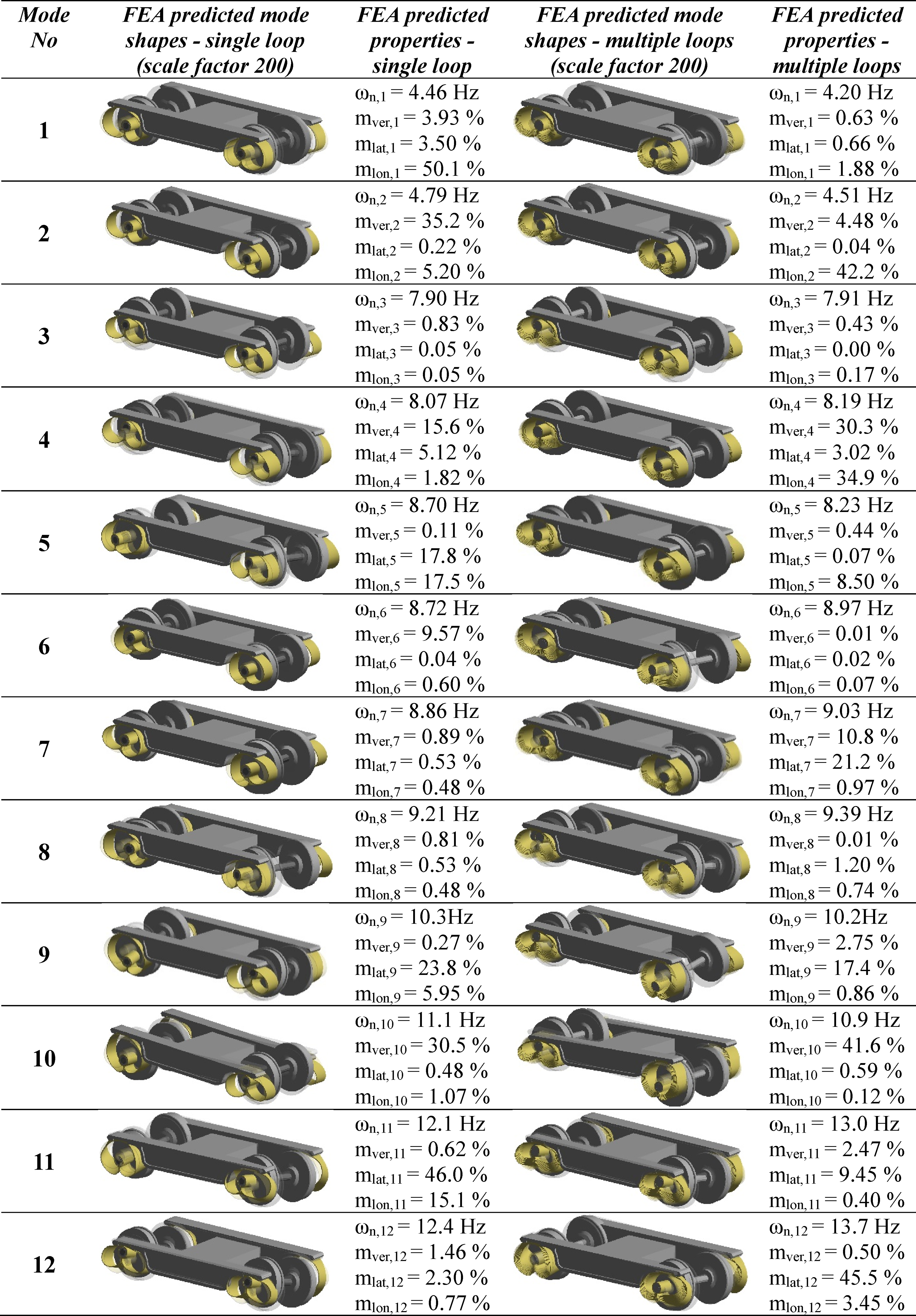
Finite element predicted results from modal analysis.
Damping plays a critical role in both primary and secondary suspension systems. For air-based primary suspensions, experimentally measured damping ratios have been reported to range from 0.24 to 0.36 under inflated conditions and from 0.05 to 0.10 under deflated conditions in the vertical (bounce) mode. 27 In the lateral direction, damping ratios for inflated conditions have been observed to vary between 0.1 and 0.24. 27 The current design incorporates a gap between the axle and the top of the resilient biasing device, which could feasibly accommodate an air spring or a high-damping rubber element. For instance, Bridgestone’s X0.6 R rubber, which exhibits a damping ratio of approximately 0.24, 28 presents a viable option for such an application. By integrating a high-damping rubber element between the axle and the resilient biasing device, the system could achieve an equivalent material damping ratio of approximately 0.1, assuming a stiffness ratio of 1.41 between the resilient biasing device and the rubber element, based on energy-equivalent damping theory. 29 In this study, a uniform damping ratio of 0.1 is assumed for all directions and modes in the vibration transmissibility analysis.
Figures 6(a) and (b) illustrate the vibration transmissibility for the two design configurations. The higher transmissibility values correspond to the dominant natural frequencies listed in Table 4, which are associated with the first 12 vibration modes. In the case of the multiple-loop design, the vibration transmissibility is generally higher, although it remains below 0.3. This is primarily attributed to the mode shapes of the thinner loops in comparison to the single-loop r0design. The single-loop design initiates vibration isolation at 13 Hz in the longitudinal and vertical directions, and at 15.5 Hz in the lateral direction. For the multiple-loop configuration, vibration isolation begins at 10.5 Hz, 14 Hz, and 17.5 Hz in the longitudinal, vertical, and lateral directions, respectively. Overall, both designs demonstrate vibration isolation capabilities at frequencies above 17.5 Hz, with the single-loop design exhibiting better vibration isolation performance. Deng et al.
30
reported vibration transmissibility measurements in the vertical direction for an existing primary suspension system, showing values greater than one within the frequency ranges of approximately 12-20 Hz and 32–42 Hz. Wang et al.
31
reported vibration transmissibility values exceeding one across a broad frequency range, attributed to the high lateral stiffness of the primary suspension system caused by the bushing design in the tested CRH3 vehicle. For further comparison analysis, the single-loop resilient biasing device was modelled using Ti-6Al-4V alloy, which has a lower sprung mass and reduced stiffness due to its lower Young’s modulus of 110 GPa and density of 4430 kg/m3. It was found that vibration isolation commences at approximately 11 Hz. From a practical standpoint, achieving vibration isolation at lower frequencies necessitates a reduction in the stiffness of the resilient biasing device. This also contributes to a decrease in yaw stiffness leading to reduction of wear at the wheel-rail interface in curving. Predicted vibration transmissibility for: (a) single-loop design; (b) multiple-loop design.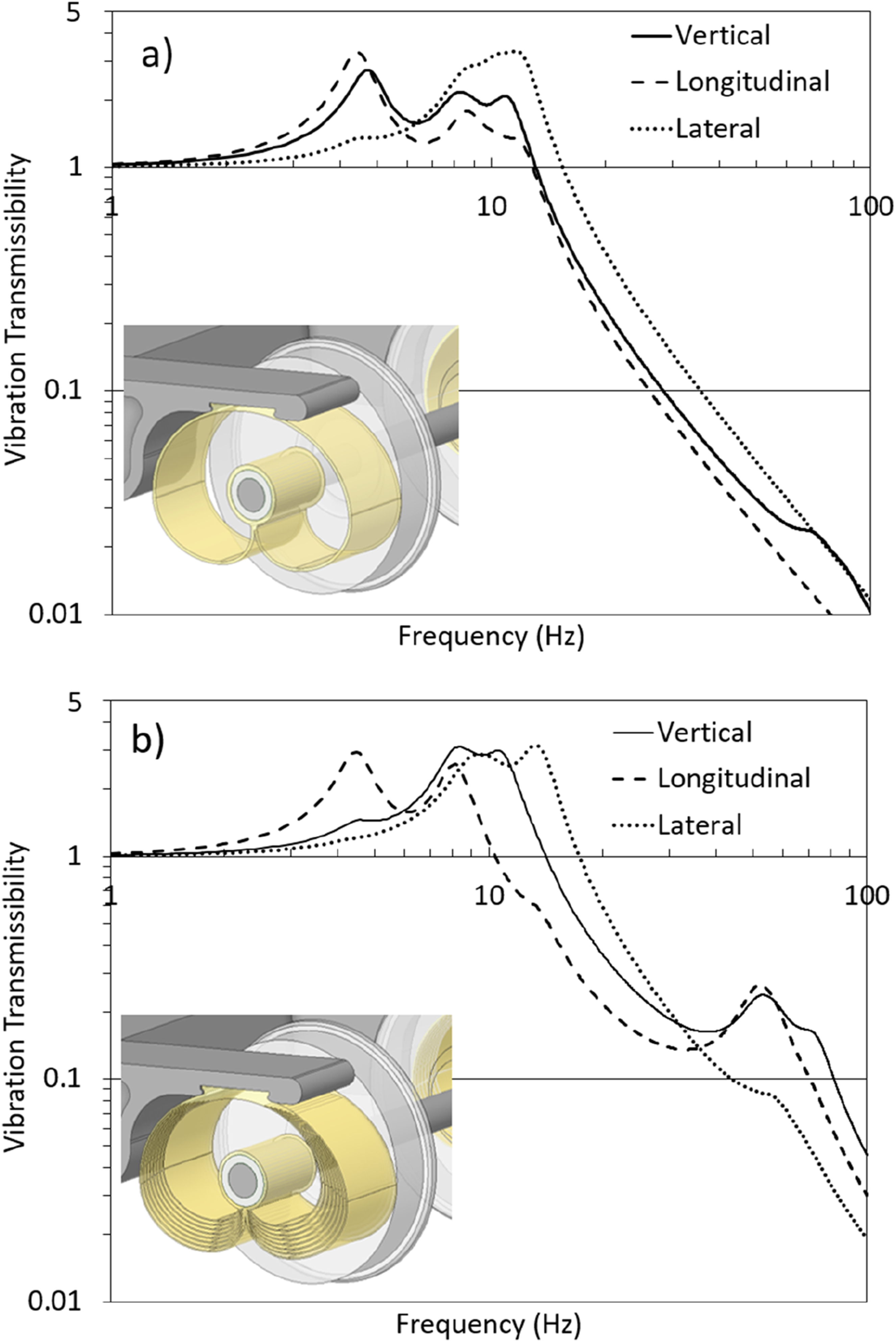
According to ISO 2631-1, ride comfort in railway vehicles is typically evaluated based on root-mean-square vertical acceleration levels, with values below 0.315 m/s2 considered comfortable and those above 0.8 m/s2 deemed uncomfortable. 9 While this study does not directly measure carbody acceleration, the vibration transmissibility values presented in Figures 6(a) and (b) provide a proxy for assessing the potential for comfort. Both design configurations exhibit transmissibility values below 0.3, indicating that the resilient biasing device can attenuate high-frequency vibrations transmitted from the wheelset to the bogie frame.
The mass of the single-loop resilient biasing device made of spring steel is approximately 120 kg, which is comparable to the combined mass of conventional axleboxes (typically 80–200 kg) and coil springs (15–80 kg) used in railway bogies. This indicates that the proposed design achieves functional integration without a significant weight penalty. Moreover, the mass can be further reduced through geometric optimisation, particularly by minimising material around the bearing housing, and by adopting lightweight materials such as titanium alloys or composite material, which offer lower density and corrosion resistance. In terms of manufacturing, conventional axleboxes are typically cast, a process that introduces risks of defects leading to fatigue life reduction. In contrast, the resilient biasing device features a 2D spiral geometry, which lends itself to extrusion, water jet cutting, or CNC machining, thereby reducing production complexity and cost. The integrated nature of the design eliminates the need for separate spring mounts and axlebox assemblies, resulting in lower labour costs and simplified logistics during assembly. Maintenance costs are also expected to be lower due to the reduced number of components and interfaces. The absence of bolted joints and separate housings minimises wear points and potential failure modes, contributing to improved long-term reliability. While a detailed cost analysis is beyond the scope of this study, the simplified architecture and reduced part count suggest that cost savings are viable, particularly in new rolling stock applications. A full lifecycle cost assessment can be conducted during the product development phase to quantify these benefits more precisely.
Conclusions
This study demonstrated the feasibility of employing the proposed novel concept of a resilient biasing device (international patent WO/2025/027292), serving as a combined axlebox and spring system, for the design of a primary suspension system in railway vehicles. Finite element methods were developed to predict the stiffnesses, induced stresses and modal dynamic properties. Vibration transmissibility model was developed and validated on a scaled-down prototype and then employed to a full-scale reference vehicle with a carbody mass of 40 tonnes and a bogie mass of 5 tonnes. The following key findings were derived from this approach. - The stiffness values achieved fall within the typical range observed in currently available railway vehicle suspensions. Additionally, the induced stresses remain below the yield strength of the material, and effective vibration isolation can be attained at high frequencies. - Two designs of the resilient biasing device were evaluated: the single-loop and multiple-loop configurations. Both exhibited comparable stiffness ratios across vertical, lateral, longitudinal, and yaw directions. Specifically, the lateral stiffness was approximately two-thirds of the vertical, the longitudinal stiffness one-third of the vertical, and the yaw stiffness was similar in both cases. - The multiple-loop design induced approximately 10% lower stress compared to the single-loop design. However, this came at the cost of a significant increase in mass, from 120 kg for the single-loop to 240 kg for the multiple-loop configuration. - The single-loop design demonstrated better vibration isolation performance attributed to additional vibration modes introduced by the thinner loop section of the multiple-loop design.
For the reference vehicle considered, comprising a carbody mass of 40 tonnes and a bogie mass of 5 tonnes, the single-loop design offers notable advantages, with the exception of higher stress levels, which may pose limitations for vehicles with greater carbody masses. Overall, the investigated stiffness characteristics, induced stresses, and vibration transmissibility confirm that the resilient biasing device is a viable candidate for use as a primary suspension system. The design can be further optimised to meet specific performance and cost requirements by adjusting the number of loops, overall dimensions, thickness distribution, and material selection. Future work will focus on integrating the device into specific vehicle platforms such as metro, regional, or high-speed trains to support higher technology readiness level development and targeted performance optimisation using multibody dynamic simulations and detailed fatigue analyses.
Footnotes
Funding
The authors received no financial support for the research, authorship, and/or publication of this article.
Declaration of conflicting interests
The authors declared no potential conflicts of interest with respect to the research, authorship, and/or publication of this article.