
Abstract
A fault-tolerant control scheme (FTCS) was developed for a novel mechatronic track switch for the first time. The FTCS was first developed and tested on a simulation model of the system, before being applied to an experimental actuation system in the laboratory. Both the simulation and experimental results show that this FTCS works as expected and allows the switch to continue operating as desired under sensor failure, preventing damage to the switch.
Introduction
Track switches (or points in the UK) are usually a railway network’s only method of transferring rolling stock between routes. Little changed in their basic function since the inception of the railways nearly 200 years ago, 1 they are a disproportionately large maintenance burden in comparison to the track distance that they occupy. 2 They are also a key operational constraint on the network. The major concern with these switches is the large number of ways in which they can have single-aspect critical failures. These failures are currently prevented by costly over-design and burdensome maintenance regimes. 2
There have been many attempts to address these fundamental issues 3 with the support of UK and European rail industry initiatives, 4 including the addition of a high-redundancy actuator (HRA) to a traditional switch to improve its reliability. 5 One such effort has been the REPOINT (Redundantly Engineered Points) project that transferred safety-critical concepts from the nuclear-power and aerospace sectors, 6 chiefly concepts about bi-mode failure and redundancy of actuation and sensing, to track switches. Work over a number of years culminated in both lab-scale demonstrators and a full-scale switch that was installed in a railway and could handle rolling-stock loads. 7 At its core, the REPOINT concept uses multiple actuators to replace the single one present in most operational switches. 8
With this arrangement, a more complicated control system is required to co-ordinate several feedback position-control systems, rather than the more traditional ‘single open-loop stall current’ detection control methods. 9 This newer system includes several feedback signals, each with its own inherent failure mode, requiring robust fault detection, isolation and fault-tolerant control.
Previously, fault-tolerant control (FTC) with fault detection and identification (FDI) has been applied to railway traction machines 10 and drives,11,12 a permanent magnet assisted synchronous reluctance motor (PMA-SynRM), 13 heavy-haul trains, 14 an actively controlled railway wheelset 15 and a magnetic levitation train.16,17
Previous work by Boghani et al. 3 focussed on methods to enable the design of these new mechatronic railway switches. Other work on these railway switches focussed only on closed-loop (not fault-tolerant) control 5 and full-scale testing 7 rather than fault tolerant and redundant actuation, which are the focus of this paper.
Outside of a railway context, FTC with Kalman filters has been applied to air-fuel ratio control of combustion engines, 18 joints of a robotic manipulator 19 and quadcopters.20–22 However, these methods have never been applied to a mechatronic railway switch before.
This new actuation paradigm with its redundant actuators and multi-input multi-output nature requires a new FTC approach to ensure safety and actuation requirements are met. This work was motivated by this confluence of factors, and was driven by a desire to devise a FTC system (FTCS) for sensor faults within this unique mechatronic railway switch.
Therefore, the novelty in this paper is the application of online FDI to a mechatronic railway switch. This has not been attempted before, nor has it been implemented in practice to show that the FTCS works as modelled. This paper is formed of four main sections: The Sensor fault detection section covers the fault detection methodology and modelling; The Simulation section covers the simulation results; The Experimental system section demonstrates the experimental validation; with conclusions drawn in The final section.
Sensor fault detection
The mechatronic switch uses sensor feedback to operate the switch, rather than the simpler ‘bang-bang’ control based on limit switches and detection of ‘stall current’ at physical limits used in the control of traditional switches. This results in a reliance on the integrity of these sensors – if sensor faults occur, these could lead to erroneous control action or in extremis instability and catastrophic failure.
Figure 1 shows the proposed layout of the FTCS for the mechatronic switch. The main closed-loop control system is based upon rotary position feedback of the actuator cams in the embedded bearers, this is a cascaded-loop control system system with inner speed and current loops. Details of the sensors can be found in9,23,24 and details of the controllers applied and tested can be found in.
9
To ensure the integrity of the system in the presence of sensing faults, the additional algorithms required are: residual generation (using input and output measurements – discussed in a later subsection); residual evaluation (using the residuals and measured outputs); and fault accommodation (used to modify the controller format if faults are present). FTCS overview for mechatronic switch.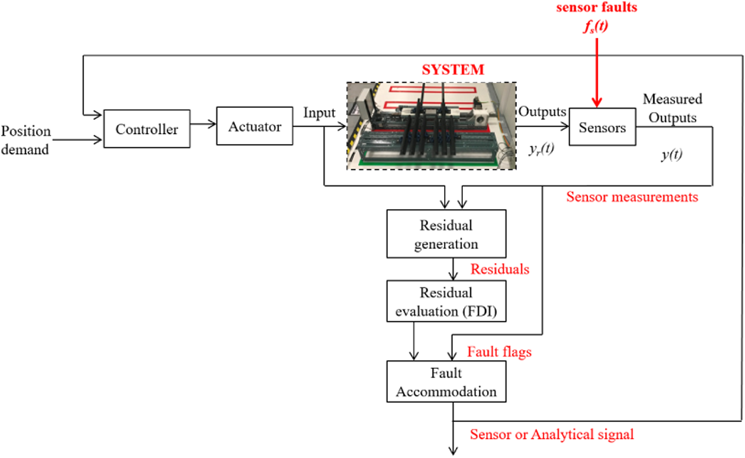
This paper focusses on faults in the velocity and position feedback signals. However, the approach is sufficiently general and has been extended to include motor current signals and one or more sensor faults, further details of which are given in. 25
Fault type definitions
Sensor faults, f
s
(t), affect actual outputs, y
r
(t), to produce measured outputs, y(t). The effects of sensor faults on the measured output can be characterised as either additive


Residual generation fundamentals
The residuals r
y
are defined here as the difference between a measured signal y and the value of an estimated synthetic signal,

If conditions are ideal, the residuals are nominally zero during normal operation and become non-zero in the event of faults, modelling errors or noise. 28 In this paper, a bank of Kalman-Bucy filters was used to estimate the outputs of the system, and these were compared to measured signals to give the residuals, which were used to determine the presence of a fault.
Kalman filter construction


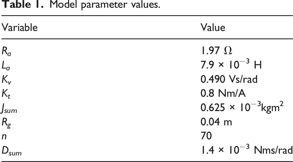
Model parameter values.
In an ideal case, where the noise characteristics are known, the process noise covariance, 

In this case, as the noise characteristics were not known, the 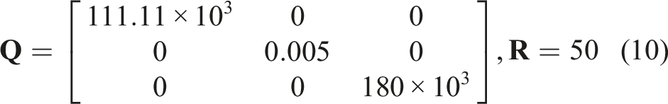
The Kalman gain, 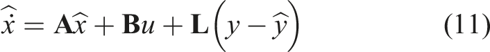


The residuals were generated independently for each of the outputs: velocity, r
vel
and position, r
pos
, using a Kalman filter for each

Fault identification using residuals
Previous research has investigated residual evaluation for fault detection.26,30,31 In this case, thresholding of the root-mean-square error (RMSE) was chosen to identify faults in a given signal. For each signal, the RMSE was generated for each signal as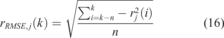
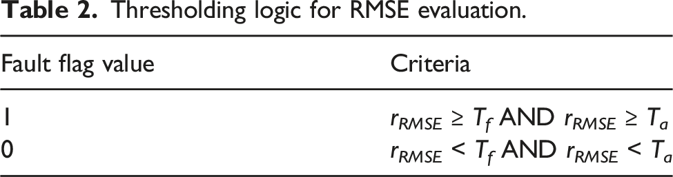
When a residual RMSE is above a given threshold, then a fault flag is raised. Two thresholds were used in this case – an adaptive threshold and a fixed threshold. The fixed threshold T f is determined using the noise variance, σ2, of the outputs when operating in steady state.
Thresholding logic for RMSE evaluation.
Simulation
The techniques as outlined in the previous section were first applied in simulation to determine an ideal level of performance. More details of the dynamic model of the laboratory demonstrator system are given in9,23,25 and a diagrammatic overview is given in Figure 2. The simulation results shown here focus on multiplicative disconnect faults affecting the position and velocity sensors, as discussed above. Schematic showing an overview of the system.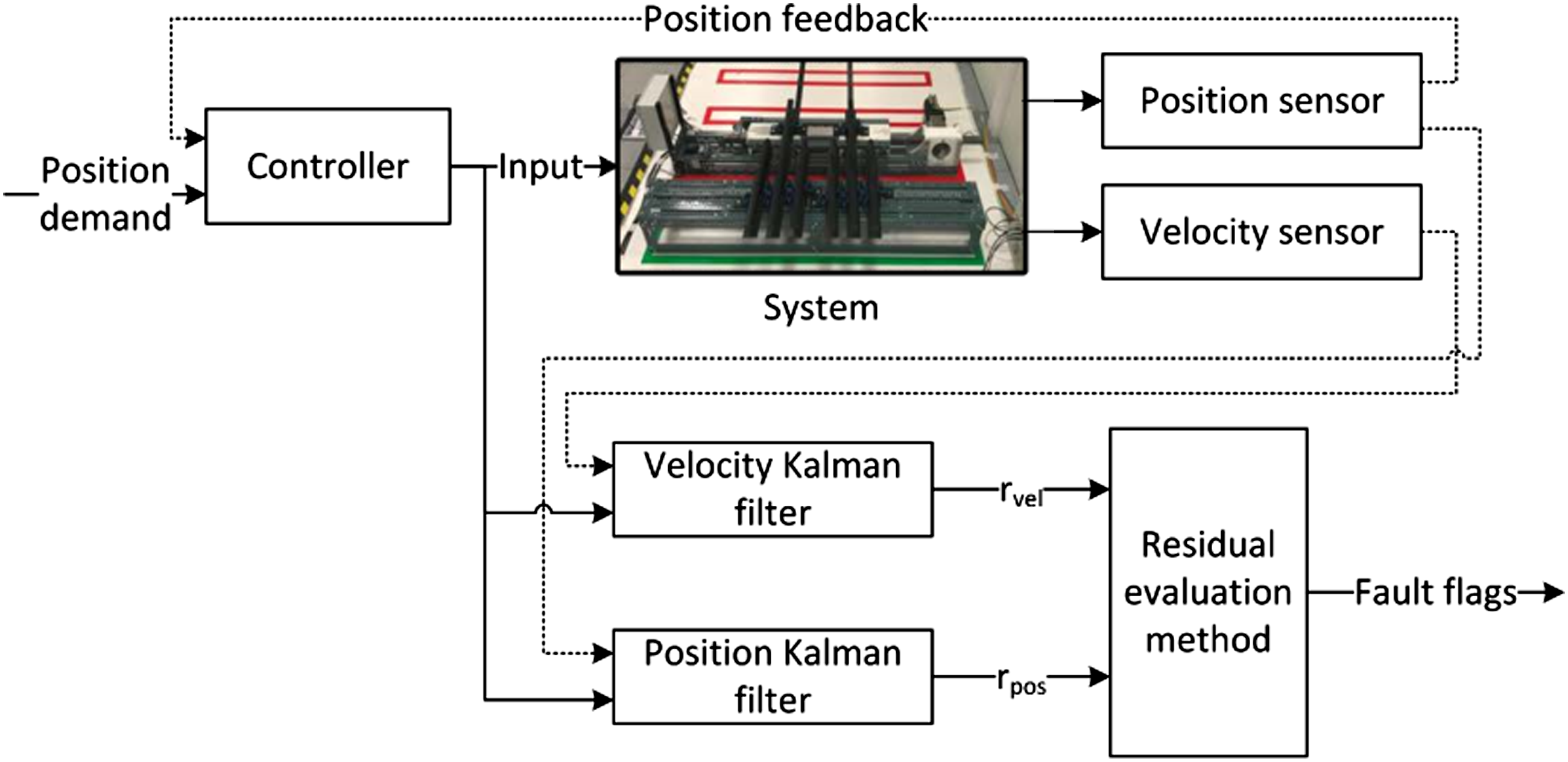
Position fault simulation results
The closed-loop system was set to follow a series of step inputs, moving the actuation system between two positions, repeating every 12s. A position sensor disconnect fault is injected at time t = 1s and the fault is removed at t = 8s, when the sensor is reconnected. The results of this test, without the FTCS active, are given in Figure 3. As a result of the fault, the peak position of the switch is 0.6 m, which is more than 5 times larger than the commanded position of 0.094 m. At t = 8s, the sensor is reconnected and the system quickly moves the rack into the desired position. The middle and lower plots in Figure 3 show that the sensor disconnect fault is quickly identified by the Kalman Filters and the threshold logic and is removed once the sensor is restored. Simulation results for position sensor disconnect fault – not accommodated.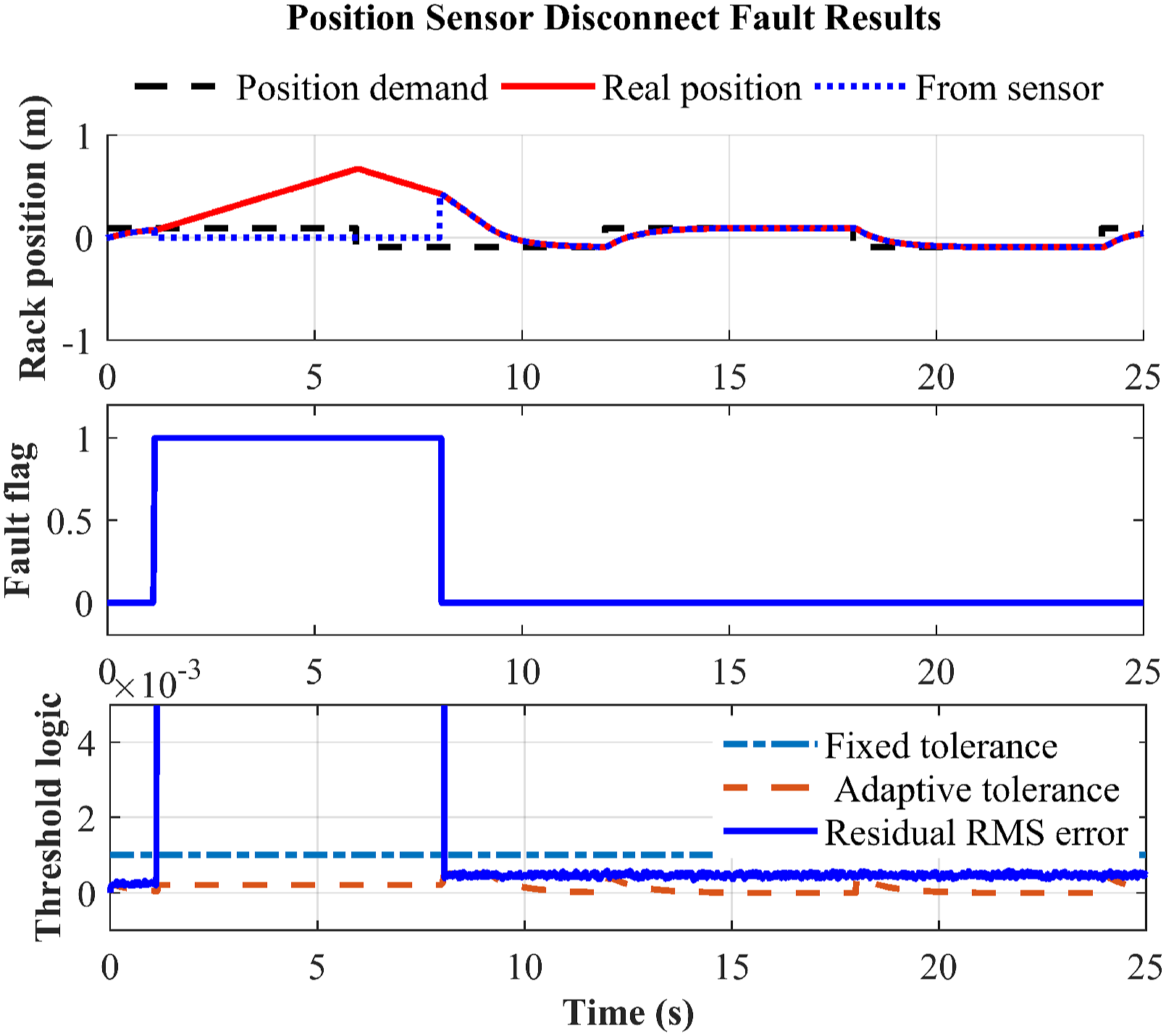
Results from the same simulation, with FCTS activated are given in Figure 4. The FCTS detects a fault, due to the growing residual, within 1 ms and replaces the faulty signal with the position estimated by the Kalman filter to allow the switch to continue normal operation. After 8s the sensor is reconnected and the residual drops below the threshold value. Note the dip in the RMSE as the Kalman filter estimate of position crosses over the zero position input from the sensor. This is not low enough to clear the fault flag, and the system continues to use the Kalman filter estimate. Simulation results for position sensor disconnect – accommodated.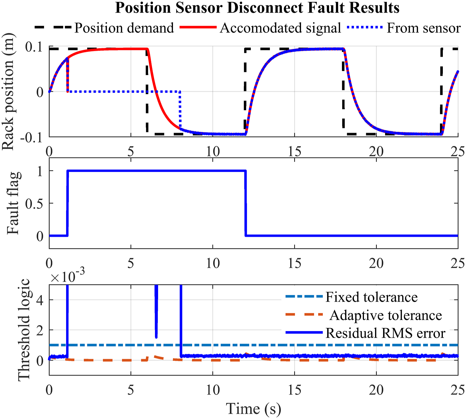
The centre plot in Figure 4 shows that the fault flag continues, and therefore the FTCS continues to use the Kalman estimate in place of the sensor signal, after the position estimate has been replaced with the now-reconnected sensor. An active control signal – a position change command – is required to disable the fault flag. This occurs at t = 12s when the system returns to a fault-free state and reverts to using the sensor signal.
Velocity fault simulation results
The simulations in the previous section were re-run, replacing the position sensor disconnect fault with a velocity sensor disconnect fault. The velocity sensor disconnect fault is injected from t = 7s to t = 15.5s. The results of these simulations with the FTCS turned off and turned on are shown in Figures 5 and 6, respectively. Simulation results for velocity sensor disconnect fault – not accommodated. Simulation results velocity sensor disconnect fault – accommodated.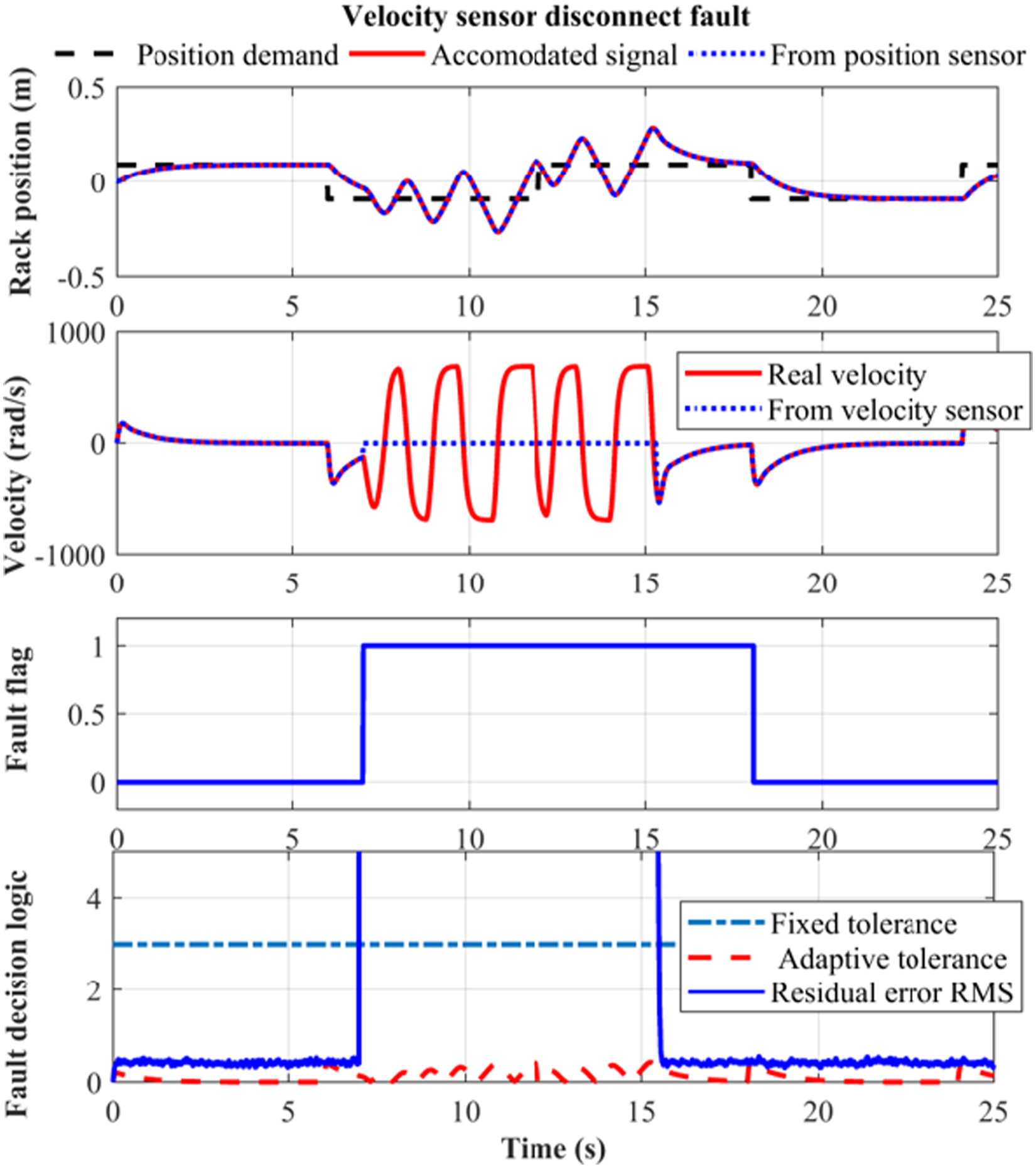
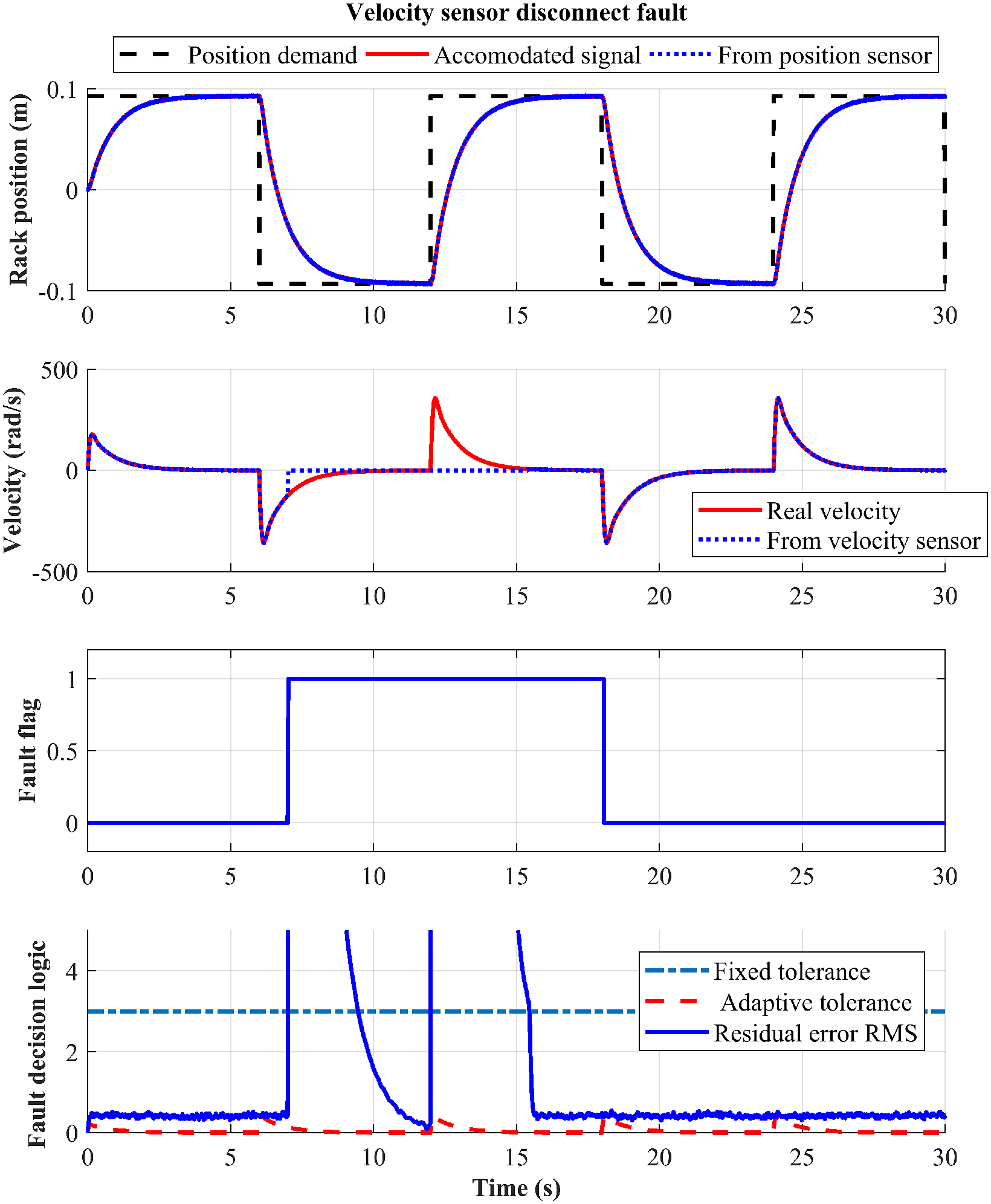
With the FTCS turned off, large oscillations are present in the simulated velocity when the sensor is disconnected. This behaviour would be dangerous and damaging to the real system.
When the FTCS is turned on, the fault flag is raised within 1 ms of the sensor being disconnected as the RMSE exceeds the thresholds. When the flag is raised, the Kalman filter estimate of the velocity is used by the controller in place of the faulty velocity sensor signal. The RMSE drops below the fixed threshold at t = 9s as the true velocity of the system approaches the zero velocity being measured by the faulty sensor. However, the residual has not dropped below the adaptive threshold, and therefore the fault flag remains. Once the sensor has been reconnected and the residuals have dropped below both thresholds, the system clears the fault flag after the start of the next position change command.
The results given in Figures 3–6 show that the FTCS operates as intended and prevents damaging and possibly dangerous errors from occurring in the track switch.
Effects of parameters
At this point, some observations about the various parameters can be made. Firstly, it is clear that the values for the fixed and adaptive thresholds are important: if they are set too high, the residuals will not trigger the FTC mechanism or will trigger it late. If they are set too low, then small differences between the Kalman filter and the real-world device will lead to false triggering of the FTCS.
Secondly, the values for the
Experimental system
The development of the experimental system is covered in detail in. 25 The main components of the system are: the computer interface running MATLAB and dSPACE control software; the dSPACE control board; associated motor drive cabinet; and the actuator bearer.
Details of the actuator bearer can be seen in Figure 7, highlighting the sensors and their positions. REPOINT bearer details.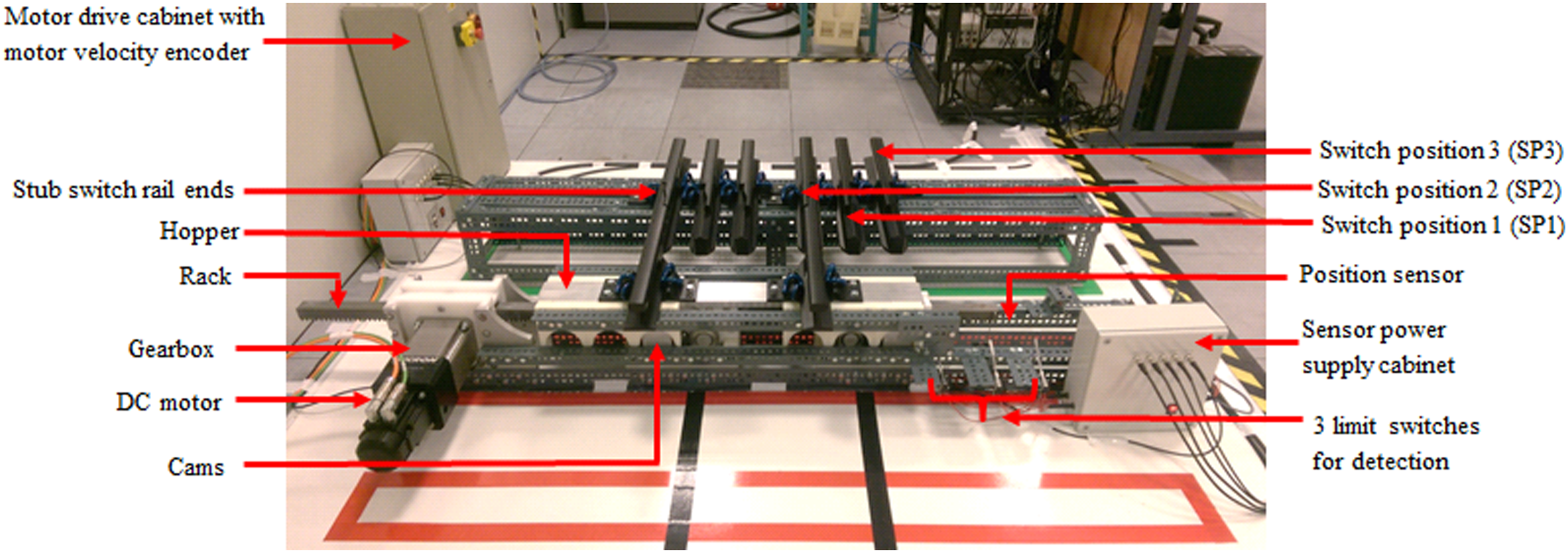
Position fault experimental results
A position sensor disconnect fault (emulated via a switch) is shown in Figure 8. The fault is injected at 128s, the position fault flag is raised and the reconfigured position estimate replaces the faulty signal within the control loop. The fault flag is raised as expected in the presence of a fault and the fault is accommodated correctly. Experimental position sensor disconnect fault – accommodated.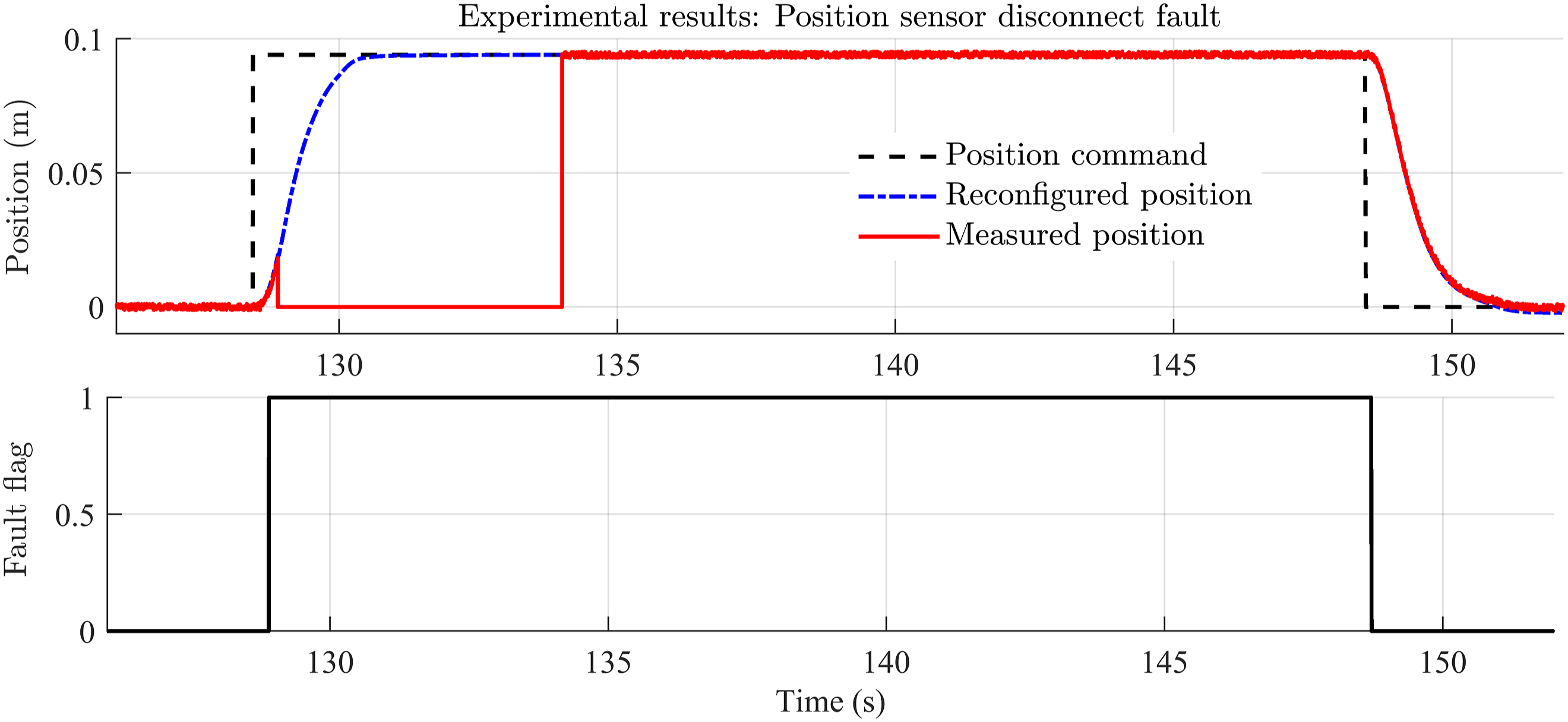
Velocity fault experimental results
Faults on the velocity signals can be accommodated in a similar fashion. A disconnect fault is shown in Figure 9 and specific details of the response are highlighted in Figure 10. The velocity sensor signal is switched to zero at 90s and reconnected at 100s. The velocity fault flag is raised almost instantaneously at fault injection with the control system reconfiguring to accommodate this. Again the fault flag remains high until the position command changes polarity. Experimental velocity sensor disconnect fault – accommodated. Experimental velocity disconnect fault – accommodated, zoomed.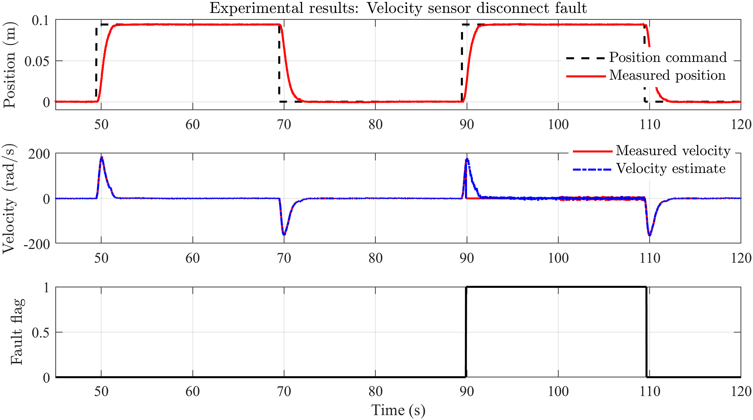
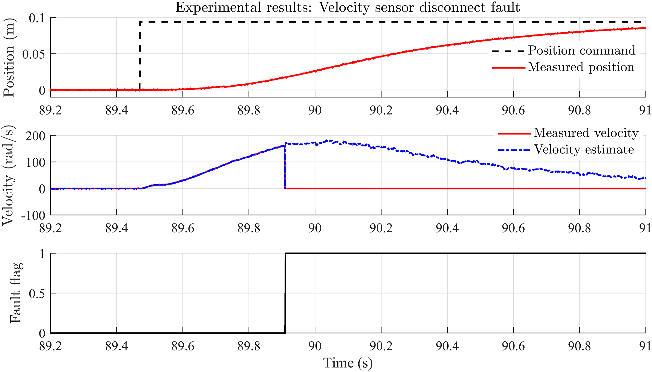
Comparison to modelling
It can be seen that the results for the constrained failure cases shown above closely follow those produced in simulation, and accommodate issues encountered with noise and modelling variation.
Conclusions
The application of a sensor-fault-tolerant control scheme is effective at mitigating faults or failures in a track switch caused by sensor faults.
Fault-tolerant control is critical for the REPOINT track switch system, due to the closed-loop nature of the control scheme and the safety-critical nature of the system, unlike traditionally actuated systems.
Through application of a residual scheme, the developed fault tolerant control system demonstrated a pragmatic solution that could be applied to a full-scale system. The modelling and demonstration system show good dynamic matching and the Kalman filter based method detects the faults well and provides the means to accommodate the fault by using estimates of the faulty states.
Footnotes
Declaration of conflicting interests
The author(s) declared no potential conflicts of interest with respect to the research, authorship, and/or publication of this article.
Funding
The author(s) received no financial support for the research, authorship, and/or publication of this article.