
Abstract
While the electrified rail network can directly utilize renewable energy sources, track electrification is costly and subject to environmental and structural limitations. Therefore, research is currently underway on alternative propulsion systems that enable overhead line-free operation. As a promising solution, the fuel cell electric drive came into focus as an emission-free drive system at the point of use. In order to be able to present a cost-efficient substitution of the propulsion systems in use today, an intensive examination of energy-optimal operating patterns, i.e. minimal fuel consumption, is crucial. This is the basis of this work, as it aims to develop an optimization algorithm that can handle fuel cell hybrid electric powertrains in a flexible and robust manner. The developed algorithm allows simultaneous optimization of the speed trajectory and on-board energy management with the aim of reducing hydrogen consumption. A comparison is made between a rule-based approach and the optimization algorithm. By simultaneously optimizing the trajectory and power distribution, 16% of the hydrogen savings potential can be achieved on a regional route in Germany compared to the rule-based approach. Finally, an in-depth evaluation of the algorithm’s ability to flexibly handle different fuel cell hybrid powertrain topologies is performed. The results show that the optimization algorithm opens up the possibility of evaluating reasonable fuel cell hybrid component sizes while achieving optimal operation. Thus, it can be used in the future to support feasibility analysis for specific use cases.
Keywords
Introduction
In order to reach the ambitious goals of CO2 neutrality, 1 a reduction in final energy consumption as an accompanying measure to decarbonization can bring considerable benefits. The final energy consuming sectors in Germany can be divided into transport, industry, commerce and households. Transport accounts for 27% of the total final energy demand in Germany, of which 73.6% is accounted for by private motorized transport in 2019.2,3 If we compare the high specific energy demand per passenger kilometre of motorized individual transport with the comparatively very low value for public rail, 4 it becomes clear that a shift to rail-based mobility solutions is a key factor in reducing today’s energy demand. To enable a seamless and convenient substitution of individual transport by rail, the existing network must be expanded to achieve the flexibility of today’s individual transport. However, building the necessary electrical infrastructure for the use of non-fossil propulsion systems is not always feasible from an economic and ecological point of view. Therefore, further emission-free and overhead line-free propulsion systems must be developed.
Current research 5 and public funding under the national hydrogen strategy in Germany 6 are investigating hydrogen as a viable route and alternative to electrification for mobility applications in the rail sector. The powertrain topologies currently under investigation are equipped with a fuel cell (FC) to convert hydrogen into electricity as the primary energy source. The secondary energy source is an electrical energy storage system (ESS) that enables recuperative braking. 7 The combination of two energy sources opens up an additional degree of freedom in meeting the power requirements between the two components. As a result, the operation of the fuel cell can be partially decoupled from the current traction demand. The dynamic power sharing between the two components therefore opens up the possibility of realizing energy-optimized and lifetime-extending operation.
Currently, there is only a limited selection of literature dealing with the energy-optimal operation of fuel cell-based rail vehicles. As explicitly highlighted by Li et al. 8 handling the power split between both components is challenging. For fuel cell hybrid energy management systems, many studies deploy some kind of Pontryagin’s minimum principle (PMP) methods. 8 On the other hand, train control and timetable compliant running times are considered by Peng et al.,8,9 by setting up an instanced co-optimization approach of a dynamic programming algorithm and a rule-based approach. Thereby, they successfully combined flexible arriving times with an efficient energy management system. Based on the research of Macian et al., 10 a direct method optimization algorithm was introduced by Schenker et al. 11 to simulate battery-electric multiple units on partly electrified tracks. The unique aspect of his work is the simultaneous optimization of the trajectory and the energy-efficient power distribution between the overhead line and the battery. This algorithm provides the basis for the work presented in this paper. The problem formulation proposed by Schenker et al. is adapted for a fuel cell-electric hybrid multiple unit.
The remainder of this paper are organized as follows. The first section illustrates the background of the applied numerical schematics. Followed by the implementation of the fuel cell model and a short grid study. Within the next section the novel algorithm is compared against a rule-based approach to investigate on the introduced algorithm’s optimization potential. Afterwards the robustness of the developed optimization algorithm towards varying component sizes is demonstrated.
Background of work
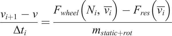
The work of Macain et al. 10 reviewed methods to numerically optimize train operation, while keeping computational demands as low as possible. For an optimal control problem (OCP) of the given train control task, the direct method (DM) approach gave the best results. Therefore, the route is discretized into a numerical grid. Each grid point contains the description equations of the physical train model and the applicable constraints. The target of the optimization is formulated in the objective function, where the train system is described by the nonlinear boundary conditions. Therefore, a straight forward extension of the model characteristics by adding further system-specific boundary conditions is possible. The optimal solution can then be computed with an NLP (Nonlinear programming) solver. For this purpose, the open source IPOPT (Interior Point Optimizer) 12 is used. The longitudinal motion model is given by an implicit solution of the following system:
The differential equation of motion, where the index point
A power setting of 100 corresponds to the maximum possible power that the electric motor can deliver. Accordingly, a power setting of −100 describes the maximum electrical braking power through recuperation that the motor can provide. The additional power setting of −200 describes the mechanical braking power that can be used, if the needed braking power exceeds the electrical brake. Therefore, below the power setting of −100, no additional power will be recuperated into the system.
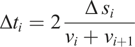
The velocity between grid points is assumed to be a linear dependence, with the remaining values between two grid points assumed to be constant. Based on the assumptions in combination with the travelled distance
As a comfort criterion, the maximum permissible values for acceleration and deceleration are defined as follows

The applicable rolling resistance forces

The powertrain model, which is based on the differential equations mentioned above, contains both general components, such as the electric motor and the power electronics, and powertrain-specific components. The power electronics and motor are based on efficiency curves taken from the EU project FINE-1.
13
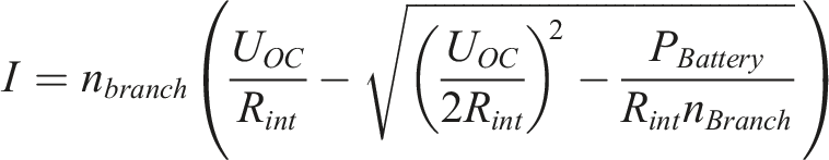
In addition, the energy storage system (ESS) is modelled in greater detail by implementing the state of charge and an ohmic internal resistance.

As most of the variables, the current
The transfer of the first and second order partial derivative matrices of the objective function and the constraints is not mandatory, but improves stability and reduces computation time compared to an automatic approximation by the program solver. 14 Therefore, the above functions are converted into newly developed automatic derivative library that provides both first and second order partial derivatives for each constraint. This allows better handling and extension of complex objective functions and constraints and facilitates the integration of the Fuel Cell Electric Multiple Unit (FCEMU).
Algorithm extension – FCEMU model
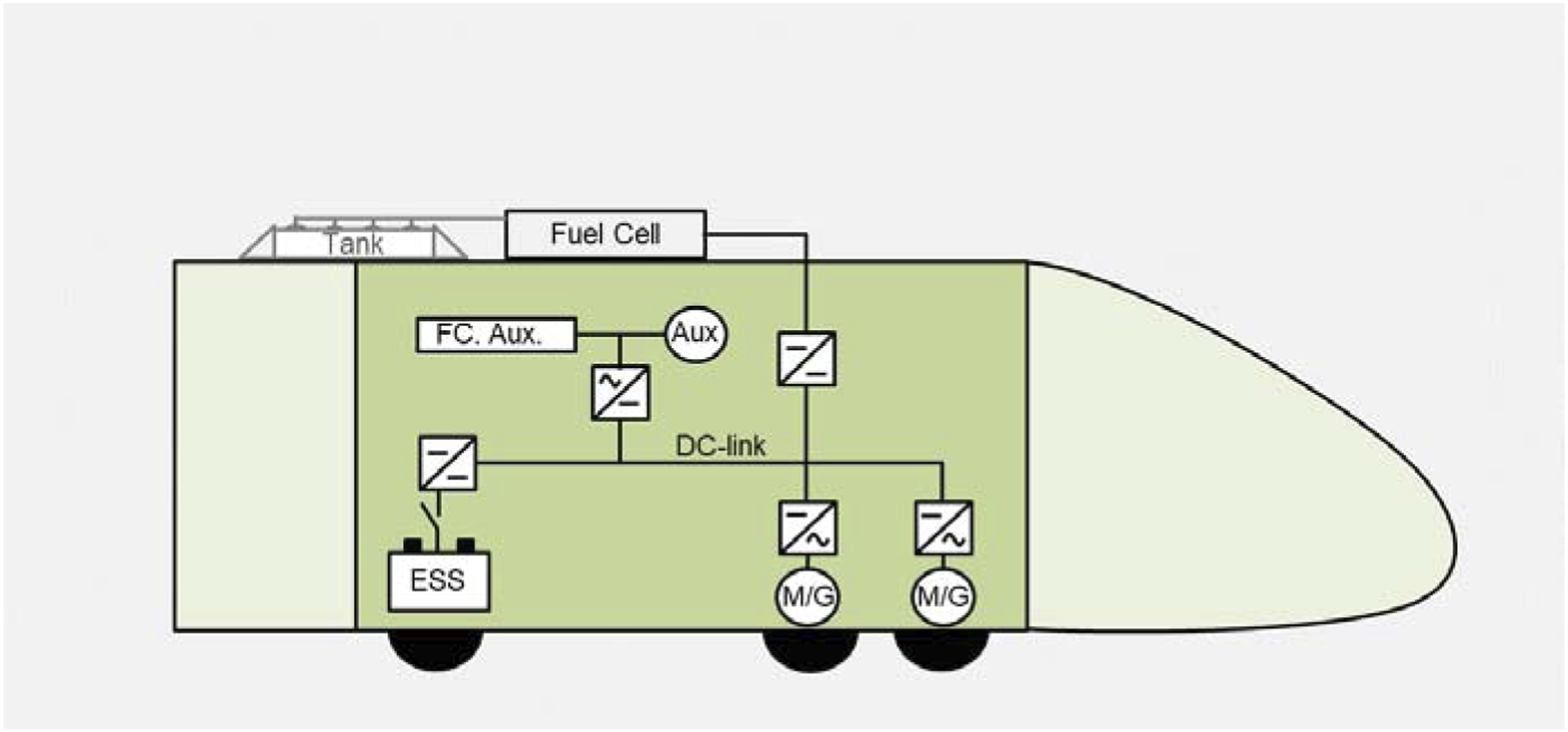
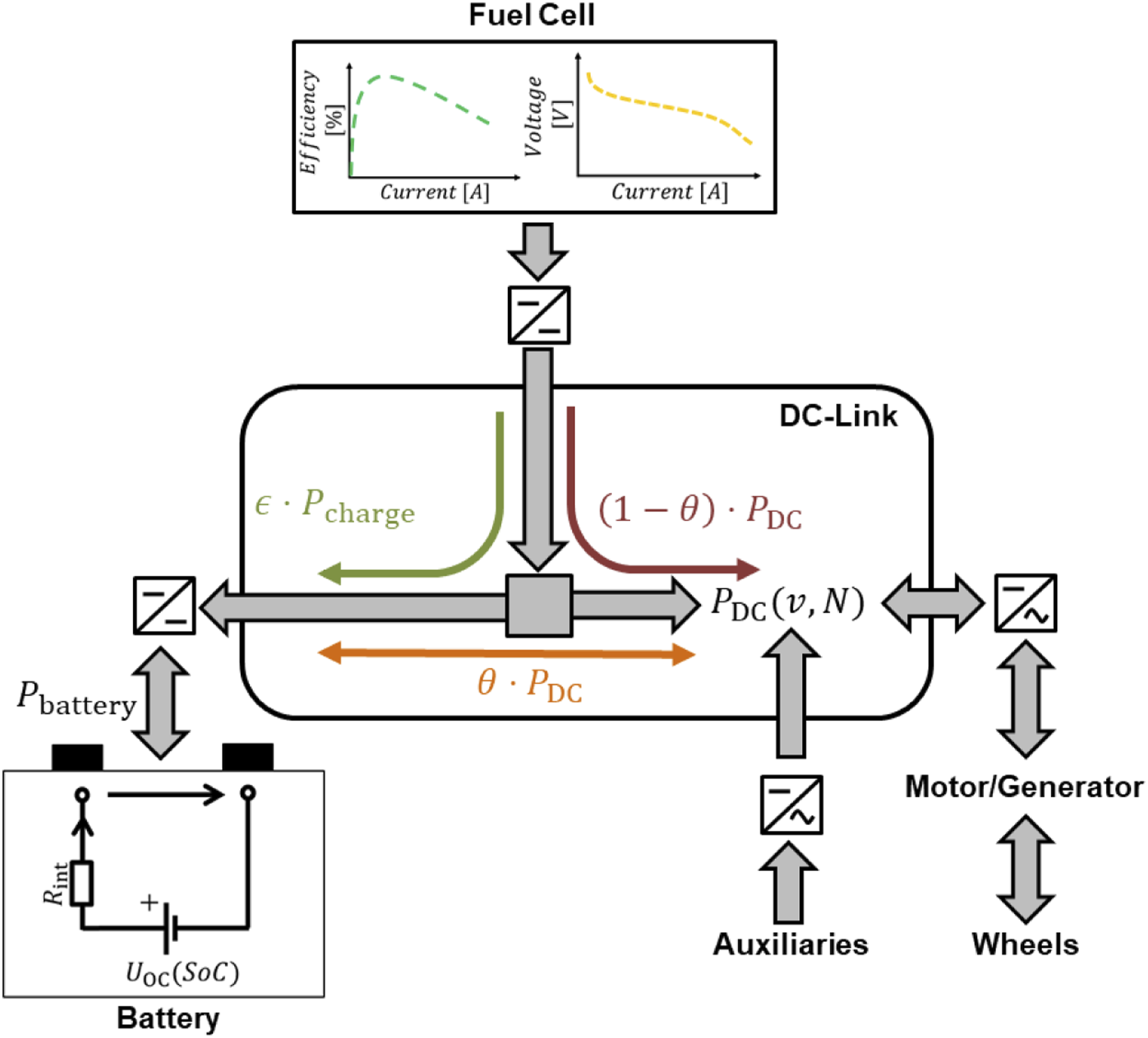
Figure 1 shows the components that are part of the mathematical model description for the FCEMU. These include the battery, power electronics and motor already presented, as well as the fuel cell and associated inverter. As shown, all components are connected to a common DC-Link. The tank is excluded from the model because its influence is assumed to be negligible for simple round-trip optimization. Schematics of components for the FCEMU model. Graphical depiction derived from Schenker et al.
11
The fuel cell model consists of a current-dependent efficiency and voltage curve. The dataset was derived from an openly accessible data sheet of the Hydrogenics HD30.
15
The operational current limits of the fuel cell

Here,
In addition to modelling the components, an investigation of the fuel cell’s aging-accelerating operating conditions was conducted and possible restrictive operating conditions were derived. According to the research results on the degrading operating conditions of the fuel cell, the limitation of the power gradient of the fuel cell is a common measure to extend the lifetime.16,17 Therefore, the fuel cell current gradient is constrained with the following implementation

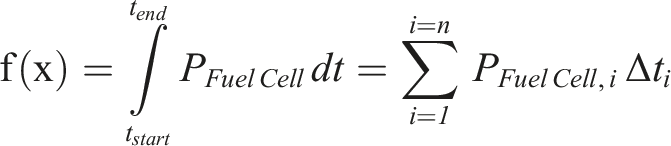
The goal of the optimization is to minimize the energy consumption. This was realized by the objective function formulation, which specifies the reduction of the hydrogen consumption of the FCEMU as the only primary energy source. The resulting hydrogen consumption is recursively calculated at the end using the heating value of hydrogen. The objective function is implemented as follows
In order to determine the power split between the fuel cell and the battery, two additional variables were introduced. Here, theta Overview of power distribution between components of the FCEMU, including the battery resistance model and characteristic curve-based fuel cell model. Illustration adapted from Schenker et al.
18
Grid study
To ensure a solution independent of the simulation step size, a grid study is performed. A compromise between fast convergence of the solver and robustness has to be found. Therefore, a generic test case consisting of a rudimentary train and a track are set up. As recommended by Schenker et al., 11 refinement layers around stations are preserved. The results obtained with the lowest resolution of 5 m grid step size is used as the reference value for this grid study. The grid study is carried out on an Intel® Core™ i7-10610U CPU @ 1.80 GHz with 16.0 GB of RAM.
Through a comparison of base step sizes from 5 m up to 1000 m, it was found that a base step size of 100 m represents a good compromise between accuracy and computation time. This resolution leads to a significant reduction in the deviation of the calculated energy demand by about 68%, while the simulation time increases by about 50% compared to a step size of 400 m. The goal of reducing the computation time as much as possible is especially important when longer distances, i.e. more grid points, are evaluated. Under this aspect, a further reduction of the step size leads to an unfavourable trade-off between further result accuracy and computational effort. The specified grid resolution of 100 m is also in good agreement with the step sizes proposed so far by Schenker et al., 11 henceforth the base step size of 100 m is taken for all upcoming simulations as the reference grid setting.
Train model data
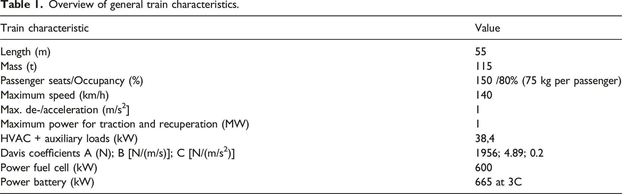
Overview of general train characteristics.
Necessary battery data as well as a feasible C-rate is drawn from the manufacturer’s data sheet or available studies.20–22
Use case route
As a use case, the regional line Plattling – Bayrisch Eisenstein – Plattling in Germany was chosen due to its demanding characteristics. The total length of the line is 143 km, with a net elevation gain of 400 m till the turnaround station at Bayrisch Eisenstein. Figure 3 displays the elevation profile and corresponding speed limits. The track has a predominant uphill slope until the turnaround destination is reached. On the return trip, the downhill sections then dominate. The driving and stop times are taken from Deutsche Bahn timetable information online.
23
The total journey time is 121 min, the turnaround time of the fictive roundtrip was assumed to be 8 min. Overview of elevation and speed limit profile of track.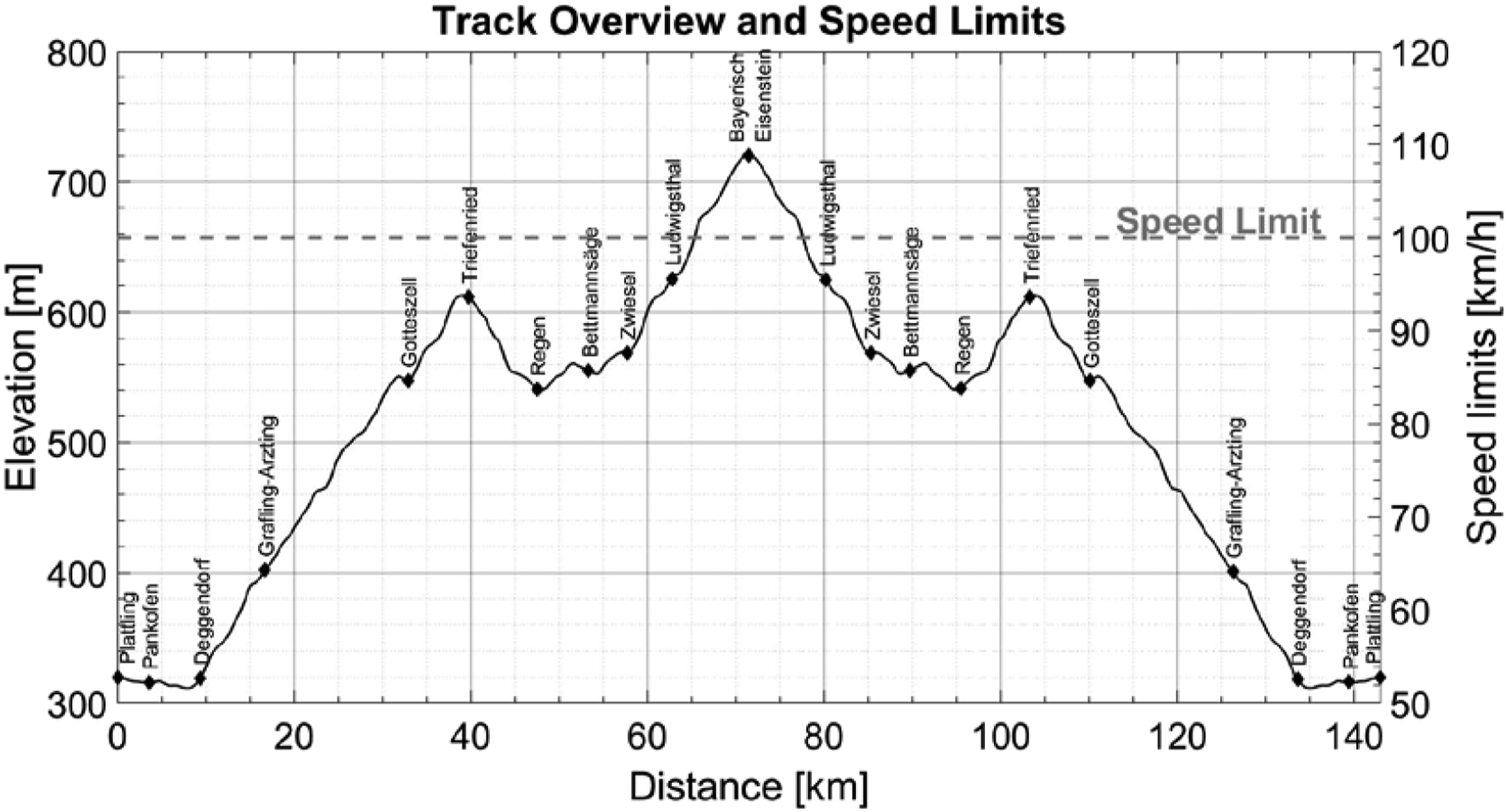
Due to limited data accessibility, a constant speed limit is set over the whole track. The speed limit was fixed at 100 km/h to enable timetable compliant operation.
Use case – Optimization verification
To demonstrate the optimization potential, the algorithm is evaluated against a sequential rule-based approach. The methodology is depicted in Figure 4. Following Scheepmaker et al.
24
the driving strategy consists of a maximum acceleration, a cruising, a coasting as well as a maximum deceleration phase. Through the deceleration phases, the train brakes with maximum recuperation and mechanical brake. This braking behaviour corresponds in the optimisation algorithm to a power control setting of Overview of the sequential rule-based approach, consisting of the Trajectory and Energy Management simulation. Included are a simplified battery resistance model and characteristic curve-based fuel cell model. Illustration adapted from Schenker et al.
18
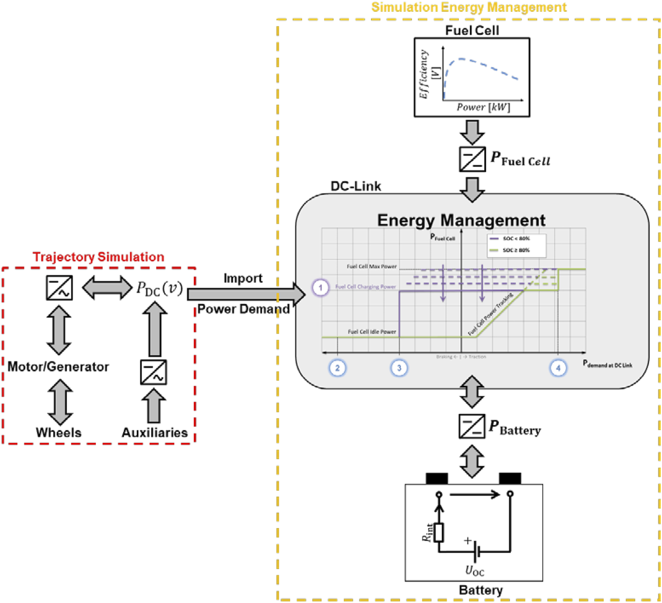
The resulting speed trajectories of both approaches are displayed in Figure 5. For the initially defined use case a timetable complaint operation could be achieved by both simulation approaches. On the outward journey, characterised by the constant gradient, clear differences can be seen between the rule-based approach (dashed line) and the optimization (solid line). On the way back, the two trajectories become more similar. This indicates a correct implementation of the coasting behaviour. The second graph depicts the SoC profile. SEnSOR can benefit from holistic optimisation and knowledge of upcoming stop times. The SoC lifts of the optimized operation during stop times (solid line) show a different charging behaviour. The optimization algorithm also charges the battery during standstill, which results in a load shift towards higher fuel cell efficiencies. The sequential rule-based approach on the other hand cannot adjust its fuel cell operation with respect to upcoming recuperation or stopping times. Comparison of the optimization based (solid line) and the rule-based approach (dashed line). The different speed profiles as well as the battery’s state of charge over the entire trip are shown.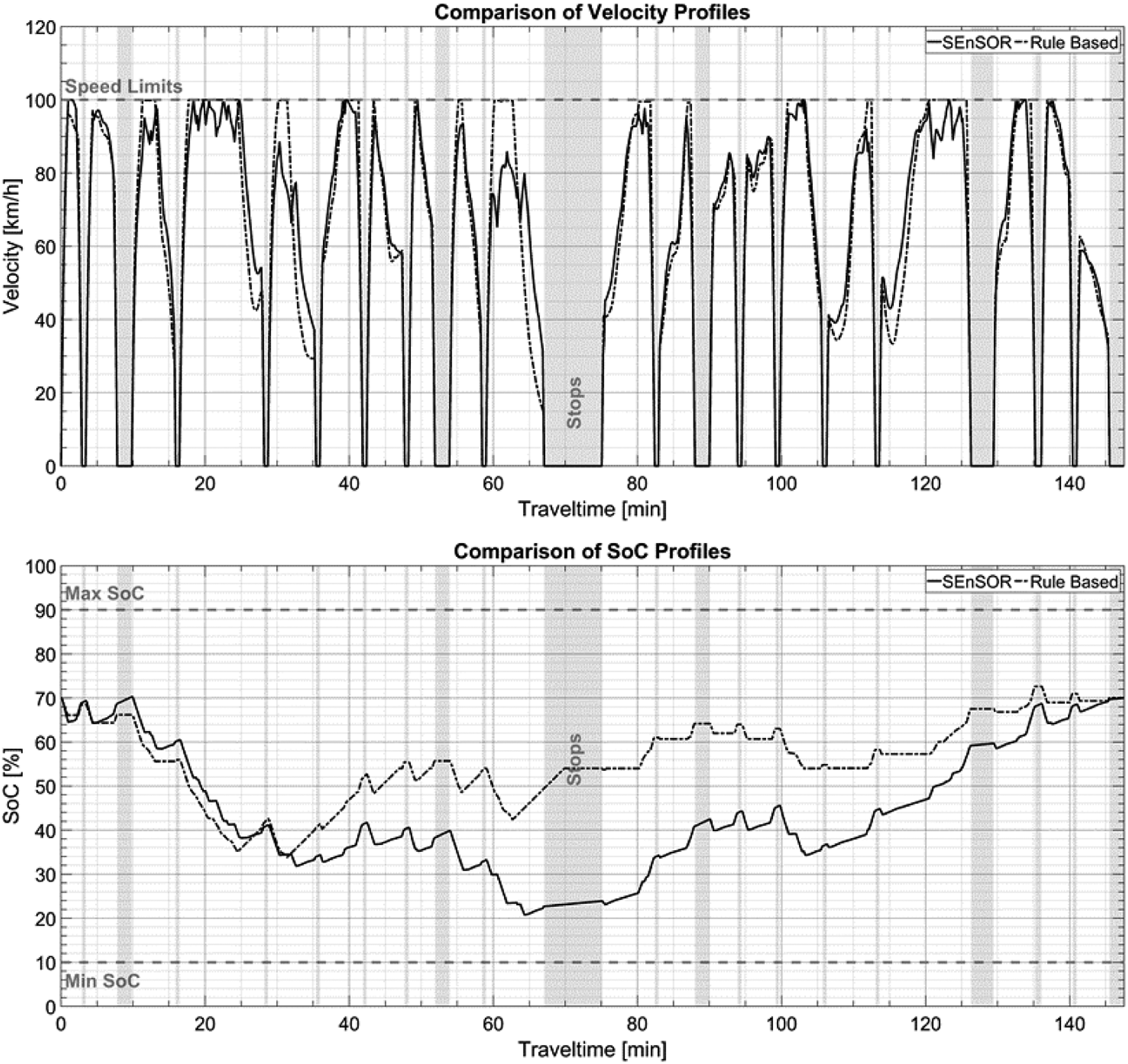
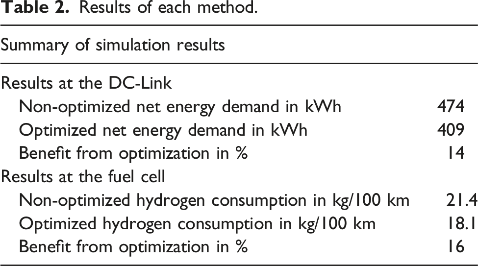
Results of each method.
Use case - Powertrain topology comparison
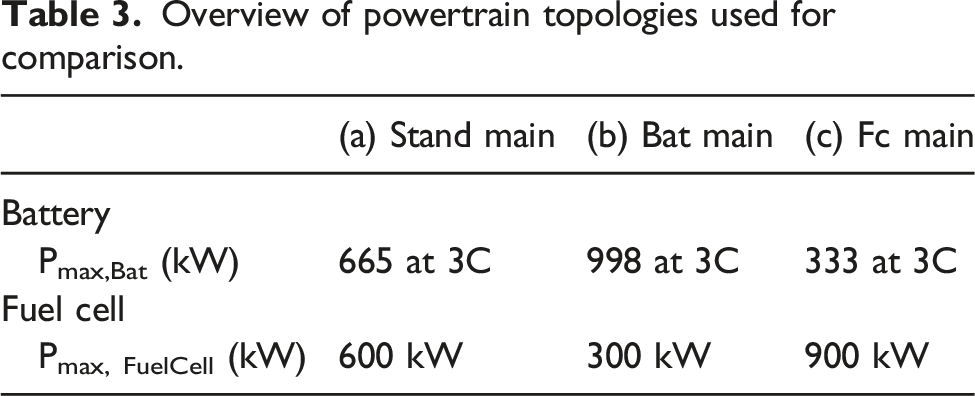
To evaluate the ability of the algorithm to robustly and flexibly adapt the operating strategy to different powertrain topologies, two additional configurations of fuel cell hybrid power units were created. The focus is on the significant differences between the primary and secondary power source dimensions to determine the variations in the propulsion system behaviour. For better comparability, the total power at the wheel was limited to 1 MW for all propulsion variants. The exact percentage of fuel cell and battery power installed varies according to the configurations. The following trains were set up for the analysis: (a) Standard Case (Stand Main): A balanced power distribution between fuel cell and battery (b) Battery Main (Bat Main): A battery-based propulsion system in which the power output of the fuel cell is relatively small (c) Fuel Cell Main (Fc Main): A fuel cell-based propulsion system in which the power output of the battery is low.
Overview of powertrain topologies used for comparison.
All three train models were successfully optimized for the previously presented use case. Figure 6 shows the SoC profiles of all three models. The biggest difference is the charging behaviour during long downtimes, especially during the turnaround time. It can be seen that the Fc Main (light grey solid line) discharges the battery during the idle periods, while the other two topologies charge the battery. Due to the comparatively low battery capacity of the Fc Main, the available threshold for storing recuperative energy and providing sufficient capacity to operate the fuel cell at higher efficiencies during charging periods is strongly limited. This indicates an unfavourable combination of FC and ESS. It also highlights the importance of a reasonably sized energy buffer so that the FC can operate at a constant power level that is used to either meet traction needs or charge the battery. This decouples the output power of the fuel cell from the instantaneous power demand. Overview of SoC profile during operation of the three different topologies.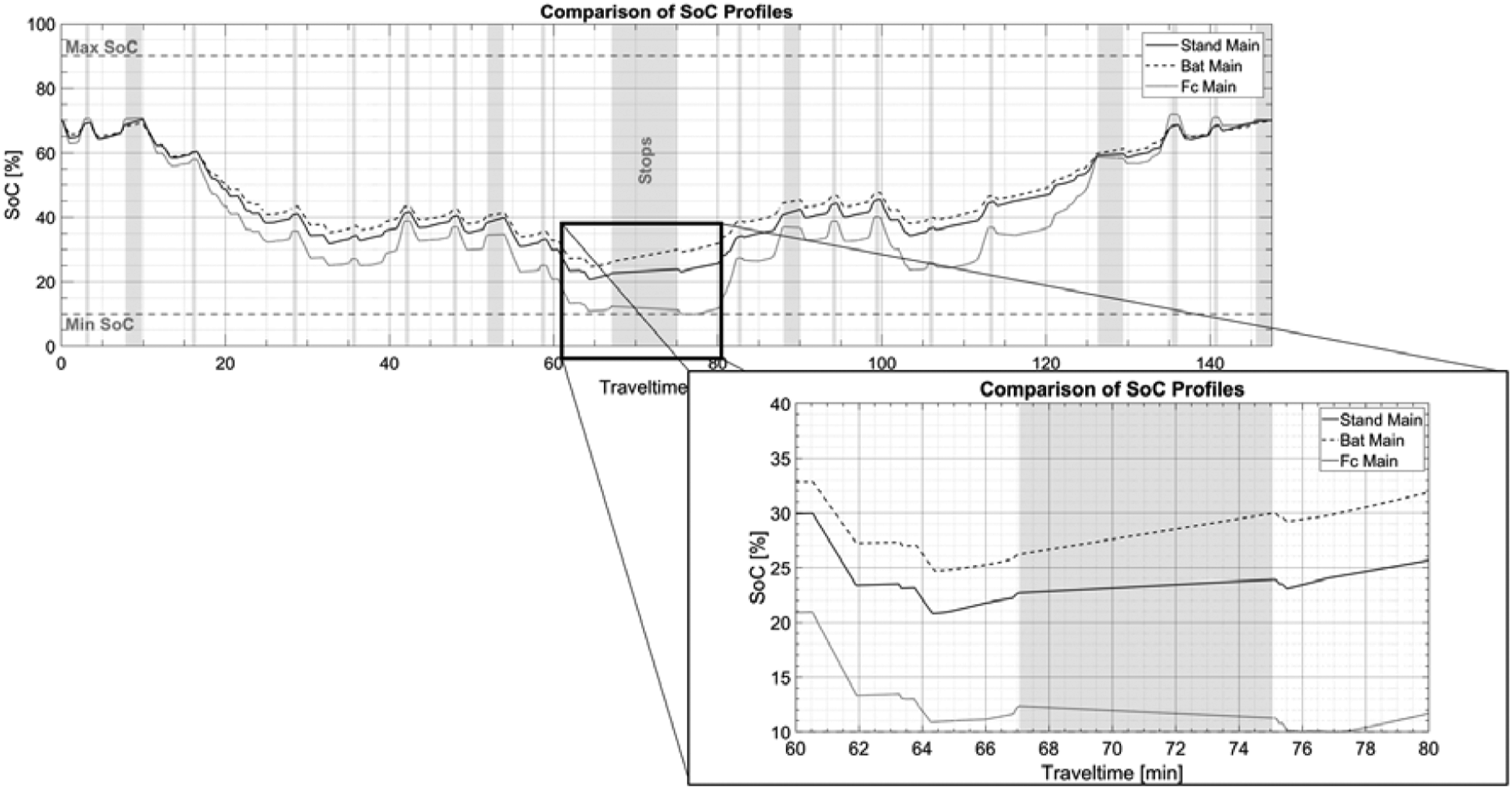
A closer look at the differences between all three configurations is possible with Figure 7. The power distribution on the DC link between the fuel cell and the battery is shown. It can be observed that as the installed fuel cell power increases, the traction demand coverage is predominantly transferred to the fuel cell. As a result, the operating window of the fuel cell expands, as evidenced by the shift from vertical to predominantly horizontal operating points. In contrast, the Bat Main model (Figure 7 (b)) with its high battery capacity uses the fuel cell mainly at a small selection of points. This results in a narrow vertical operating point corridor and is equivalent to using a range extender. In addition, the fuel cell can never be operated at idle in this configuration. The Stand Main case (Figure 7 (a)) shows operation around the points where the traction demand is shared equally between the fuel cell and the battery. Overview of power split at the DC-Link. (a) Stand Main case; (b) Bat Main, (c) Fc Main.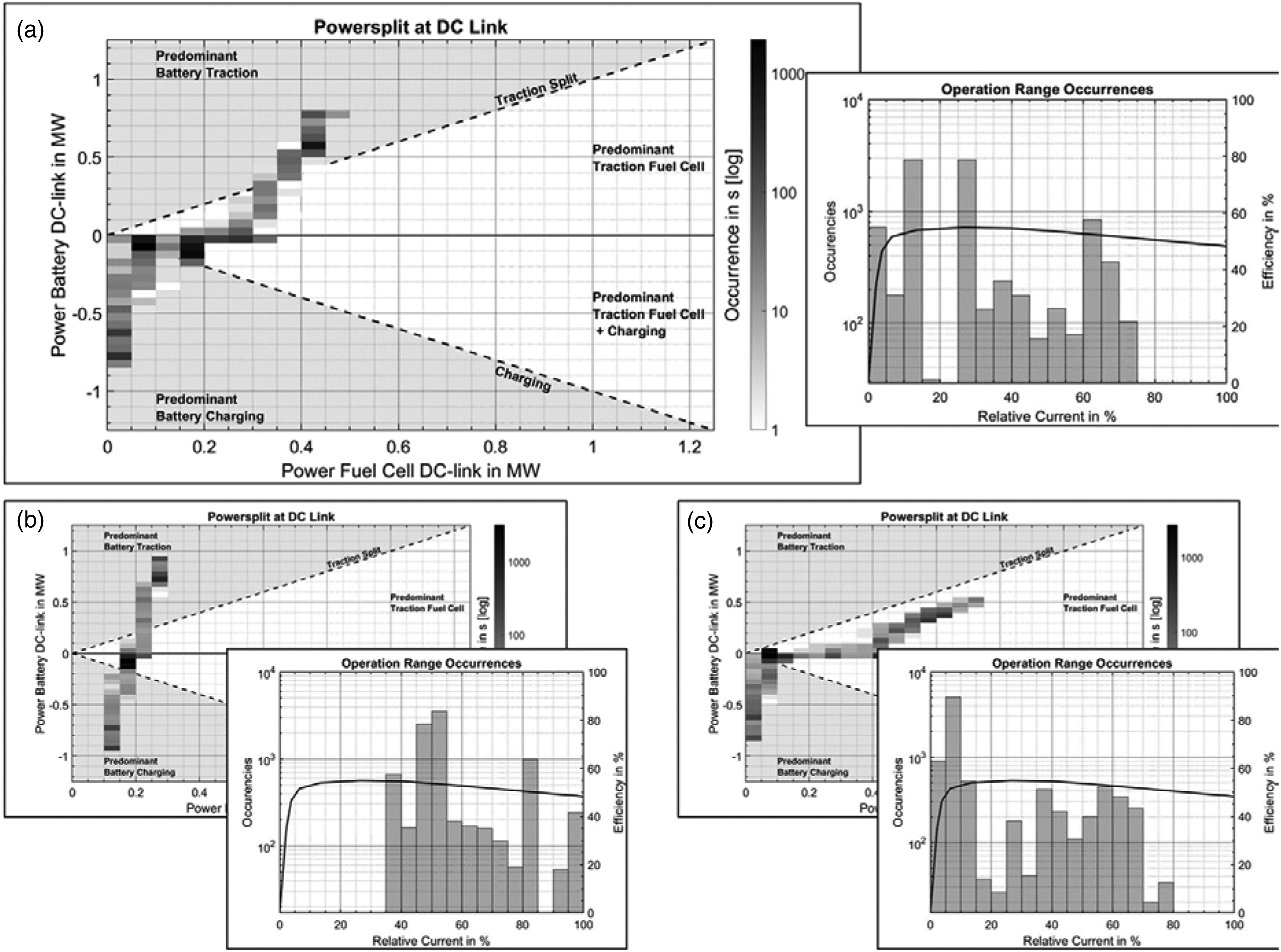
Comparison of the distribution of fuel cell operating points in correlation with the fuel cell efficiency curve shows the following picture in Figure 7: For the Fc Main case (Figure 7 (c)) a large operating window directly affects the ability to run the fuel cell near its high efficiency. In particular, the points with lower currents show a significant drop in fuel cell efficiency. In contrast, the majority of the Bat Main model (Figure 7 (b)) operating points are near the right side of the fuel cell efficiency maximum, resulting in more efficient operation of the fuel cell.
Comparison of hydrogen consumption.
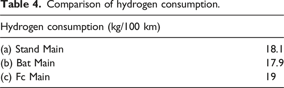
In summary, when switching from a battery- to a fuel cell-dominated propulsion system, the operating points of the fuel cell must directly match the traction demand. Therefore, the additional degree of freedom for hybrid electric vehicles is neglected. This results in the least favourable trade-off between installed fuel cell power and available on-board energy buffer for the FC Main model, leading to significantly less efficient operation. In summary, it has been shown that the algorithm can successfully handle different composition propulsion systems in a flexible and robust manner by adapting the operation strategy to the component dimensions.
Discussion and conclusion
In this paper, an algorithm was presented that enables the simultaneous optimization of on-board energy management and speed trajectories of fuel cell electric multiple units. The algorithm is based on a direct optimization approach for battery electric multiple units. 11
The implemented topology of the fuel cell multiple unit considers a fuel cell with current-dependent voltage and efficiency as well as additional auxiliary loads to provide cooling for the fuel cell. Additional boundary conditions to prevent fuel cell shutdown and high loads, as well as a constraint on the ramp up behaviour of the fuel cell were presented.
The fuel cell model was tested and the algorithm was evaluated with respect to a grid-independent solution by a grid study. This study showed that a discretization step size of 100 m, together with refinement layers around the stations, provides a very accurate result, while computation times are still within an acceptable range. After numerical verification of the model, a use case was created: a generic regional train derived from existing models and prototypes was set up to operate on a very challenging, hilly regional line in southwestern Germany (Plattling - Bayerisch Eisenstein). This use case was simulated in two different ways, with a rule-based model and the novel optimization algorithm. Both methods provided stable and physically feasible results. However, the results differed significantly in the velocity trajectory itself and in the on-board energy management. The proposed algorithm was able to reduce hydrogen consumption on a regional route in Germany by about 16% compared to a rule-based approach. One reason for this is the holistic optimization of train operation by the developed optimization algorithm. This proactively uses run-out phases and the altitude profile to reduce power requirements at the wheels. The power distribution between fuel cell and battery as well as the recharging strategy were also successfully adjusted by the optimization algorithm. The difference in the mode of operation during idle periods is particularly striking. Here, the optimization algorithm realizes a load point shift of the fuel cell in order to operate it with higher efficiencies while gradually charging the battery.
An evaluation of the ability of the developed algorithm to adapt its behaviour to different fuel cell hybrid powertrain dimensions was then performed. For this purpose, three trains with different ESS capacities and installed fuel cell power in each case were set up. In order to isolate the component dimensioning as the predominant factor influencing the adaptation of the operation strategy, the traction power was limited to 1 MW for all three models. Charge sustaining operation at the end of the cycle was required as a boundary condition. It was shown that the optimization algorithm robustly and flexibly adapts the power distribution to the varying component compositions. The train trajectories exhibit differences that could be attributed to the varying component sizing and optimal operating window of the fuel cell. In addition, limitations in the powertrain topologies could be worked out with the fuel cell-based propulsion system. The ESS of this topology was not sufficiently sized for this particular application to allow the fuel cell to operate within its optimal operating window.
In summary, the proposed direct optimization algorithm for simultaneous speed trajectory and energy management optimization for a fuel cell electric hybrid multiple unit has been successfully implemented. The algorithm shows an optimization potential of about 16% for hydrogen consumption in a regional train in Germany compared to a rule-based approach. The final evaluation of different component sizes has shown that the proposed algorithm can serve as an evaluation tool for necessary and reasonable component sizes for a specific application.
Further research could be carried out in various directions. Worth mentioning is the need of a more detailed fuel cell model implementation, as it currently relies only on its electricity. As described by Kandidayeni, 26 temperature is a second valuable indicator for accurate modelling of fuel cell degradation and its mitigation of such operation conditions. In addition to increasing model accuracy, a step could be taken toward real-time performance. In this regard, current research is working on a combination of real-time predictive energy management systems built on non-real-time optimal control algorithms as supervisors. 27
Footnotes
Authors contributions
Florian Kühlkamp: Writing – Original Draft, Conceptualization, Methodology, Software, Formal Analysis, Visualization
Moritz Schenker: Writing – Review and Editing, Conceptualization, Software
Marcel Konrad: Review and Editing, Supervision
Holger Dittus: Review and Editing, Supervision, Project administration
Declaration of conflicting interests
The author(s) declared no potential conflicts of interest with respect to the research, authorship, and/or publication of this article.
Funding
The author(s) received no financial support for the research, authorship, and/or publication of this article.