
Abstract
This paper presents numerical analyses of a welding simulation of a bogie frame side beam. The simulation is based on an analytical thermal model coupled with a non-linear structural finite element model using shell elements enabling the welding simulation of large structures. The predicted clamping forces, distortions, and residual stresses for different clamping conditions and plate thicknesses are analysed in terms of manufacture. A new fatigue model based on the endurance limit approach is proposed using residual stresses to predict the S-N curves. The predicted S-N curves with the proposed model showed close correlation with the S-N curves for class F and class F2 welds of the BS7608 standard, demonstrating its validity and potential use in design.
Keywords
Introduction
A train bogie is a mechanical structure underneath a railway vehicle. Its main use is to provide support for the main body. It also provides the train with a stable platform to move by absorbing the vibrations from the track and balances the effect of centrifugal forces in curvatures. Bogie frames are manufactured by cutting of steel plates with specified thicknesses determined in the design stage. The plates are welded together to form the bogie frame which should be structurally durable. Tee and butt joints are primarily used in the welding of plates to assemble the bogie frame. Depending on the type of filling, the welds can be defined as a full penetration or partial penetration. It is preferable that all welds of the bogie frame are full penetration. However, due to access limitations, some of the welds are made with partial penetration, in particular the welds in the inner sides of the bogie frame.
Welding is widely used in industry as a main joining method. It uses a heat source to melt a piece of material and join parts together. The melting is followed by rapid cooling and local shrinkage at the melt pool causing the material to generate residual stresses, which cause structures to distort. Distortion can lead to dimensional inaccuracies which might not be acceptable in industry leading to a large number of experimental iterations to mitigate the level of distortion by developing a clamping system, modifying the stiffness of the clamps, change of power and speed of the heat source, change of geometry by adding extra stiffness or change of welding path and sequence. All these variables can lead to costly design of experiments to understand how best to develop the welding process for a specific application and deliver welded product with distortion within specified tolerances. Mitigation methods such as, applying hot or cold spots respectively in front or behind the welding heat, shot and ultrasonic peening as well as small amounts of compressing which results in a reduction of tensile residual stresses has been researched. 1 However, in practice, it is difficult to apply those methods as many welds have complex geometries and finding the appropriate heat source is arduous to do. Another solution to control distortion is the use of clamping systems. In terms of structural integrity, standards for fatigue assessments have been developed to guide designers how to best design railway structures including bogie frames. 2
Simulation of the welding process has been seen as a tool to help the development of the welding process. 3 Analytical models have been developed in the past to predict the temperature field in a semi-infinite body. 4 Those models have the limitations of capturing the non-linearities due to temperature dependent thermal properties and geometrical boundary conditions. With the increase of the computational power, the finite element method has been used to address those limitations in the past. Researchers have modelled the heat source and predict the temperature distribution in different geometries. 5 Later, coupling of thermal and structural analyses have been advanced to predict the mechanical behaviour of the welded structure. 6 The coupling of the thermal model has been done either sequentially or simultaneously. In the sequential approach, the thermal model is solved for a given time interval. The coupling is done by creating thermal load cases as an input for the structural mechanical analysis. Due to the different convergence criteria for the thermal and the structural mechanical analyses, the temperature is interpolated for the given time. In the simultaneous approach, the thermal equations are coupled with the mechanical equations for calculating the strain values by incorporating the thermal equations into a thermal expansion model for the calculation of the thermal strains which are used to calculate the mechanical response. The simultaneous approach is more challenging in terms of numerical convergence because it needs to satisfy thermal and mechanical equilibrium conditions for a given time increment. 7
Despite the evolution of the computational power, the simulation of the welding process is still under pressure to deliver computational efficiency demanded by applications with large structures. Prediction of the melt pool and understanding the effect of power and velocity on the melt pool dimensions have been widely researched for comprehensive material and heat source models. 3 One of the key computational challenges to simulate the welding processes of large structures is the large number of finite elements required to discretise the geometry. For example, for a 2 m × 2 m structure requiring welding passes of 30 m for a melt pool with an approximate size of 6 mm, requiring at least 3 elements to accurately capture the effects of the heat source, this would result in a large finite element model requiring enormous computational time. Many industrial applications consist of joined plates where shell elements can be used. The use of shell elements in welding simulations has been found to deliver very similar results to modelling with solid elements. 8 Furthermore, the inherent strain method has been used to reduce computational time and enable the welding simulation of large structures. This is a method where strains are directly applied into the finite element solvers. Some promising results have been published for large structures, 9 as well as bogie frame side bars to predict the final distortion. 10 The disadvantage of this method is that it is applied as a single step where all strains in the welding zones are added at the same time. This enables the prediction of the final distorted shape, but it lacks the ability to predict the history of the deformations and the reaction forces of the designed clamping system.
To address the challenges in welding simulation of large structures, a fast hybrid numerical model is proposed in this study to simulate the welding process by delivering fast computational solution through coupling an analytical thermal model with a structural finite element model that uses shell elements. The model was applied to a railway bogie frame to understand the effect of the welding process on the clamping forces, residual stresses, and distortion. Using the predicted residual stresses, a novel fatigue model capable of predicting S-N curves in the welds is proposed to further exploit the use of the predicted residual stresses from the welding simulation in the design stage.
Methodology
Overview
Figure 1 illustrates the methodology used in this study. For the simulation model of welding, inputs such as geometry, mesh, material model and properties, boundary conditions, heat source and toolpath of the heat source are essential. The boundary conditions are needed to represent the clamping system of the welding process. The outputs of the simulations are residual stresses, distortions, and clamping forces. The predicted clamping forces and distortion are used to analyse the manufacturability aspects of the process while the residual stresses are used to predict S-N curves in the welds. Overview of methodology.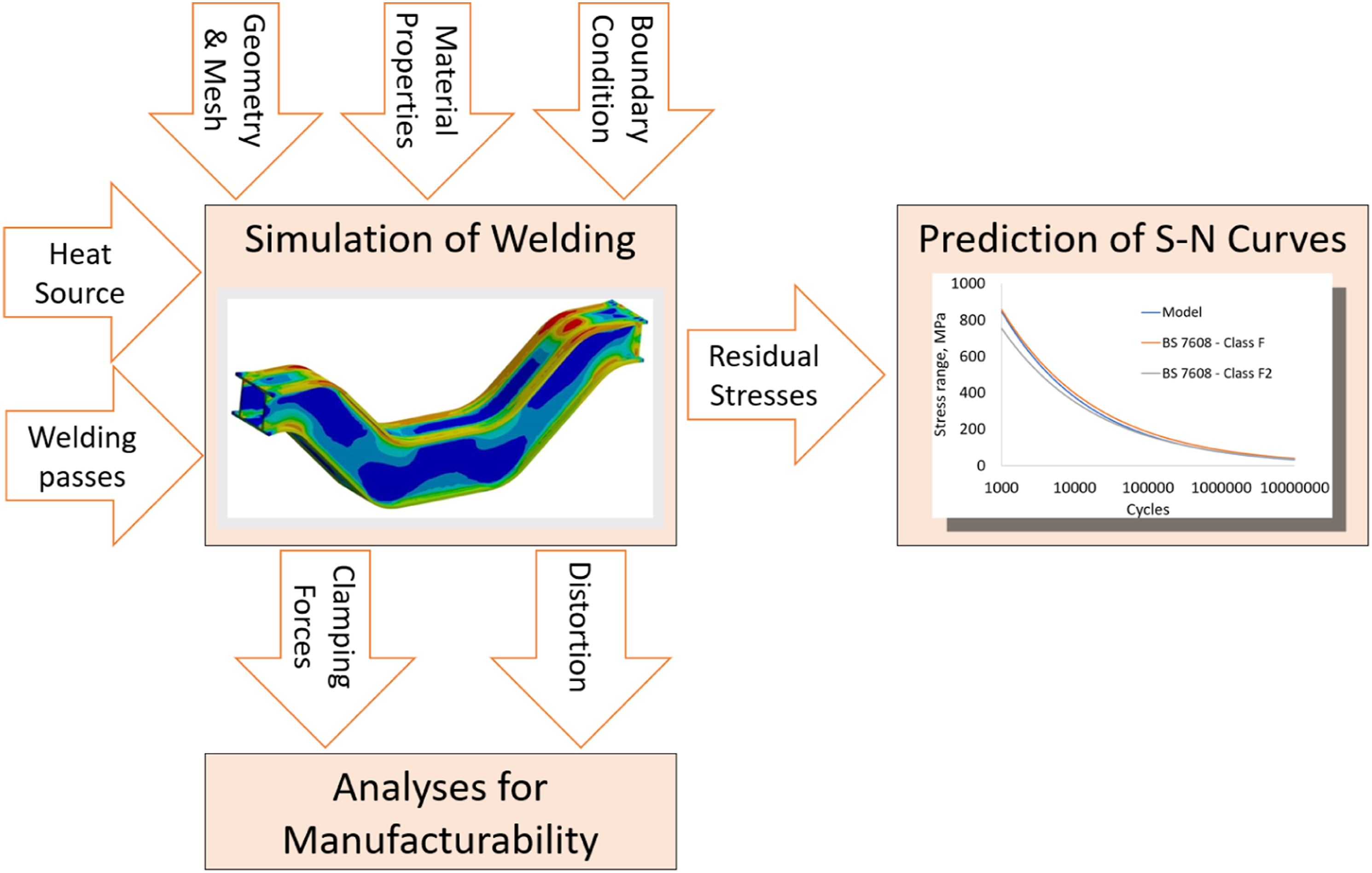
Simulation of welding
A bogie frame side beam is created as a solid model in Autodesk Fusion 360. The solid model was converted into a shell model using the midplane approach. The shell model was imported in ANSYS Mechanical and meshed with 13,697 quadratic shell elements (Shell 281 from the ANSYS library). The surface geometry was meshed with a seeding of 10 mm at the weld edges and 30 mm elsewhere. The overall dimensions and the clamping location are shown in Figure 2. Finite element model.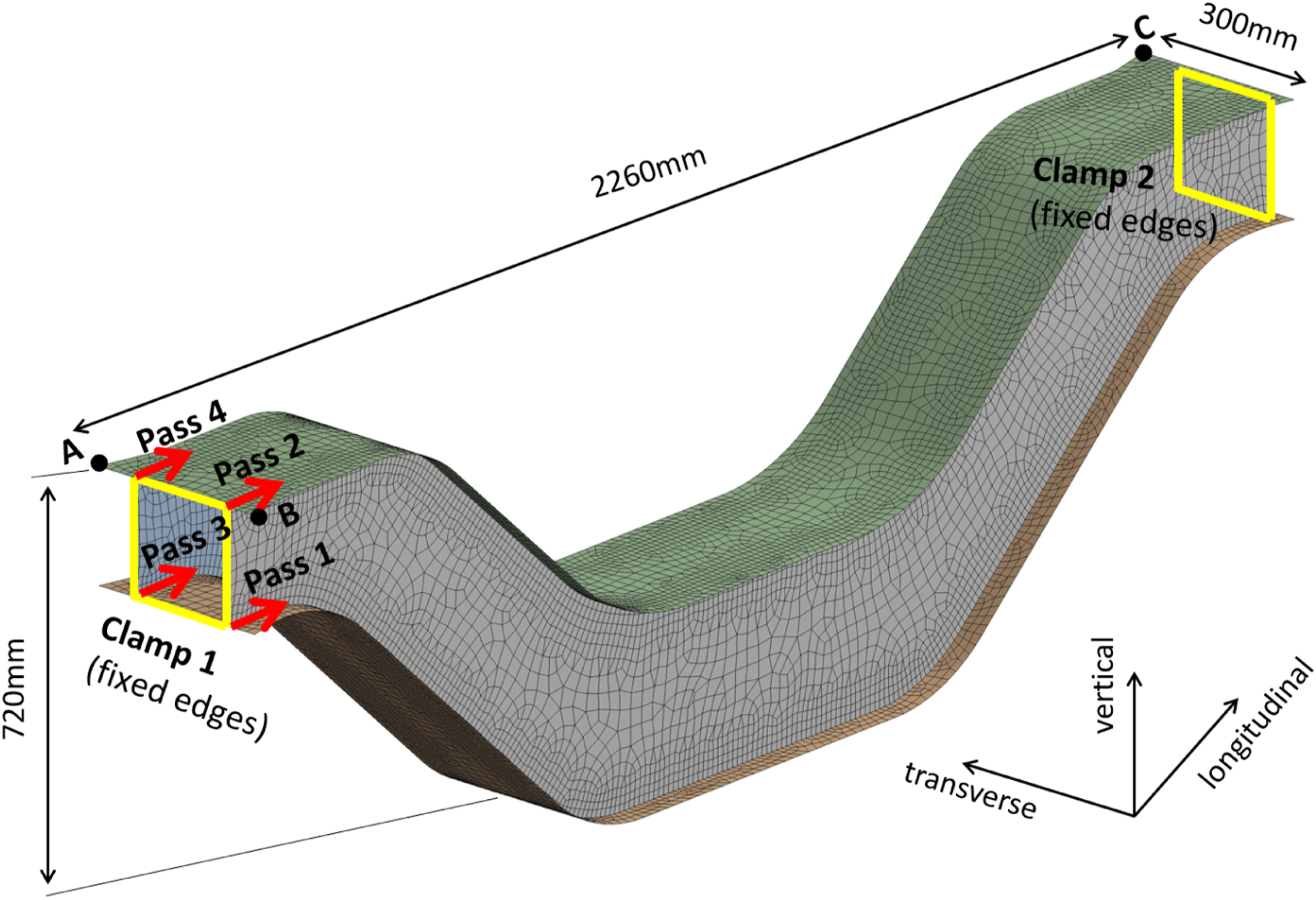
Zero displacements in the three directions (longitudinal, transverse and vertical) were applied to the clamped edges (clamp 1 and clamp 2) in order to represent a clamped condition. An unclamped condition is simulated by replacing the zero displacements in the three directions at clamps 1 and 2 with boundary conditions applied at three nodes of the mesh (nodes A, B and C). Zero displacement was applied to node A in the three directions, nodes B and D were constraint in the vertical direction and Node B was also constrained in the lateral direction. This change of boundary conditions enables the stresses to redistribute and predict the displacement after the clamps are released. A simulation with no clamping was conducted using the boundary conditions at the three nodes throughout the complete simulation of the welding process. The results from the three conditions are used for comparison and analyses.
Material properties for structural steel S355.
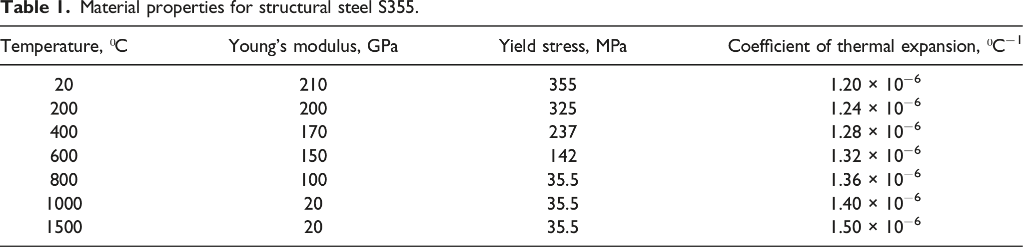
The effect of the plate thickness was modelled by changing the thickness values of the shell elements. Four plate thicknesses were investigated (12 mm, 16 mm, 20 mm, and 24 mm) to understand the impact of the plate thickness on the reaction forces in the clamping system as well as on the residual stresses and distortion.
The temperature field for a semi-infinite body with a power distribution applied at a point of the body with coordinates (x', y', z') can be given by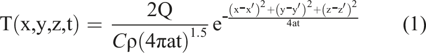
Equation (1) is used to describe a moving temperature field with isotherms defining a constant shape of the temperature field by using a specific heat capacity of 700 Jkg−1 ⁰C−1, density of 7800 kgm−3, thermal diffusivity of 5.510−6 m2s−1, effective power of 300 kW and time of 20 s. The same temperature field model was used and validated for prediction of residual stresses and distortion in selective laser melting. 11 The temperature field was moved by changing the coordinates x′, y′, z′, which represent the centre of the heat source. The coordinates of the meshed geometry remained unchanged (x, y, z). A toolpath was created to navigate the temperature field. The toolpath and the analytical temperature field were implemented into ANSYS using algorithms implemented by APDL commands.
Temperature changes are calculated as the difference between two temperature fields for a given node of the finite element mesh. The temperature differences are then used to calculate the thermal strains using the thermal expansion model. Based on the induced thermal strains, elastic-plastic calculations are conducted to calculate the residual stresses and deformations. The modelled melt pool represented the actual weld dimensions. To avoid convergence issues at high temperatures, a cap on the yield stress was introduced, which was 10% of the yield stress at room temperature. 12 The same limit was applied to the Young’s modulus in order to avoid high non-linearities in the melt pool which may lead to a non-convergence. A cap on the calculated maximum temperature using equation (1) was added to be equal to the melting temperature of 1500°C.
Fatigue model
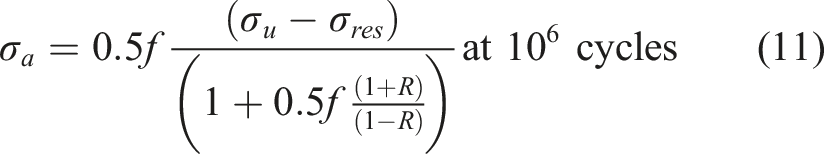
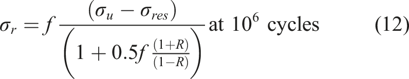
The fatigue model in this study is based on the endurance limit approach at 

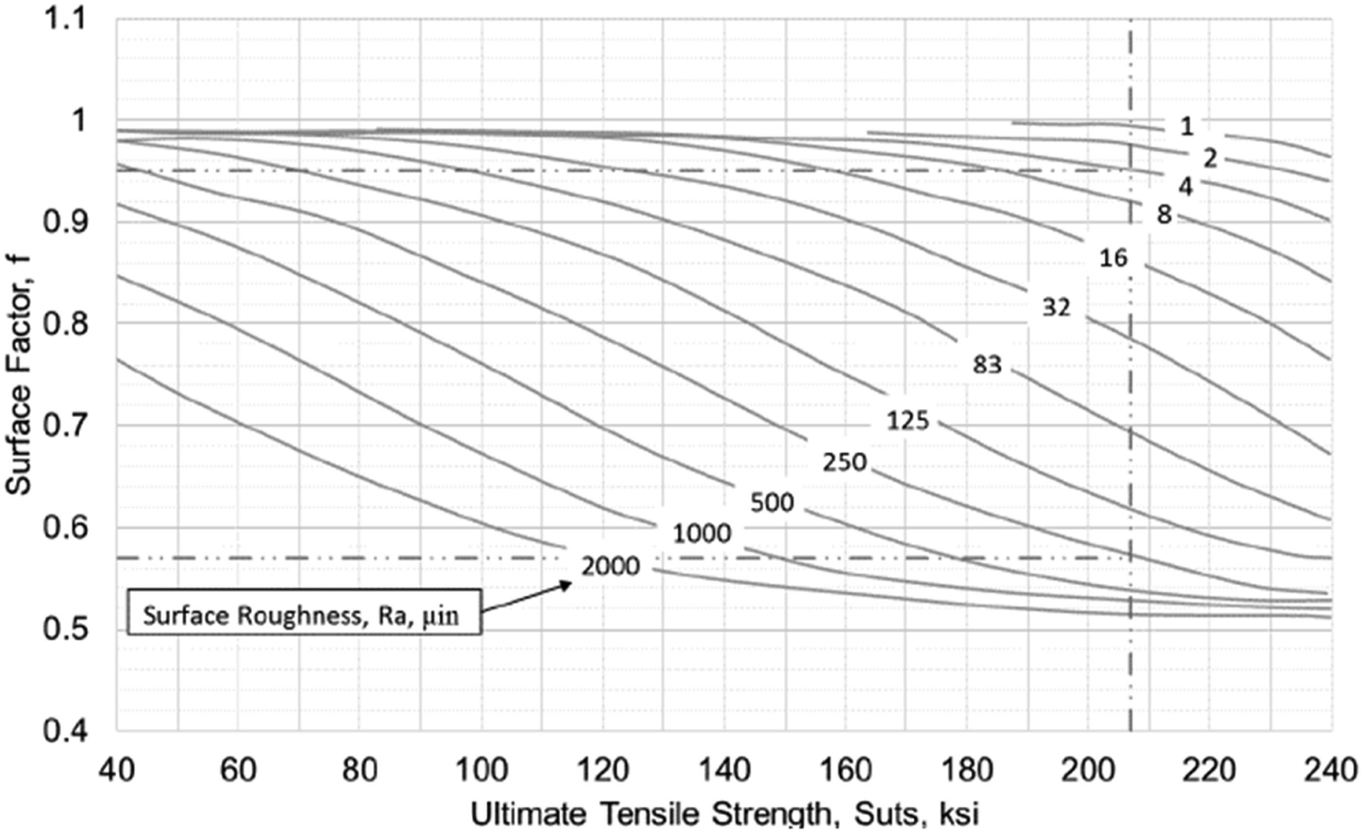
It is well-known that fatigue cracks can initiate at the surface due to the effect of the surface roughness. The surface roughness is represented in the endurance limit approach by a surface factor, Fatigue surface factor for metal parts.
16

The effects of mean stress can be represented using the Goodman approach,
14
where equation (4) can be expanded to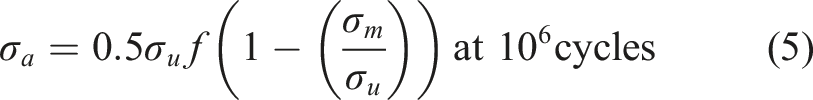


Results and discussion
Analyses for manufacturability
The generation of residual stresses is unavoidable in welding. Figure 4 shows the predicted maximum principal residual stresses at the bottom and top welds respectively. The results show the residual stresses generated at the end of the welding process while the bogie frame side beam is still clamped, after the clamps are released and a case where no clamping is applied. It can be seen that the maximum principal stresses increase at the bottom weld (Figure 4(a)) after the bogie frame side is unclamped. However, the opposite effect is observed at the top weld where the residual stresses decrease after unclamping. Another observation is that the peak maximum principal stresses are located at the curved geometrical features at the top and the bottom welds. This indicates that the geometry also affects the generation of residual stresses. For the condition where no clamping is used in the simulation, the predicted residual stresses are higher at top and bottom welds compared to the predicted residual stresses using clamping at the two ends. This indicates that clamping has some benefits to the reduction of the induced residual stress. Predicted maximum principal residual stresses for a plate thickness of 16 mm at the: (a) Bottom weld; (b) Top weld.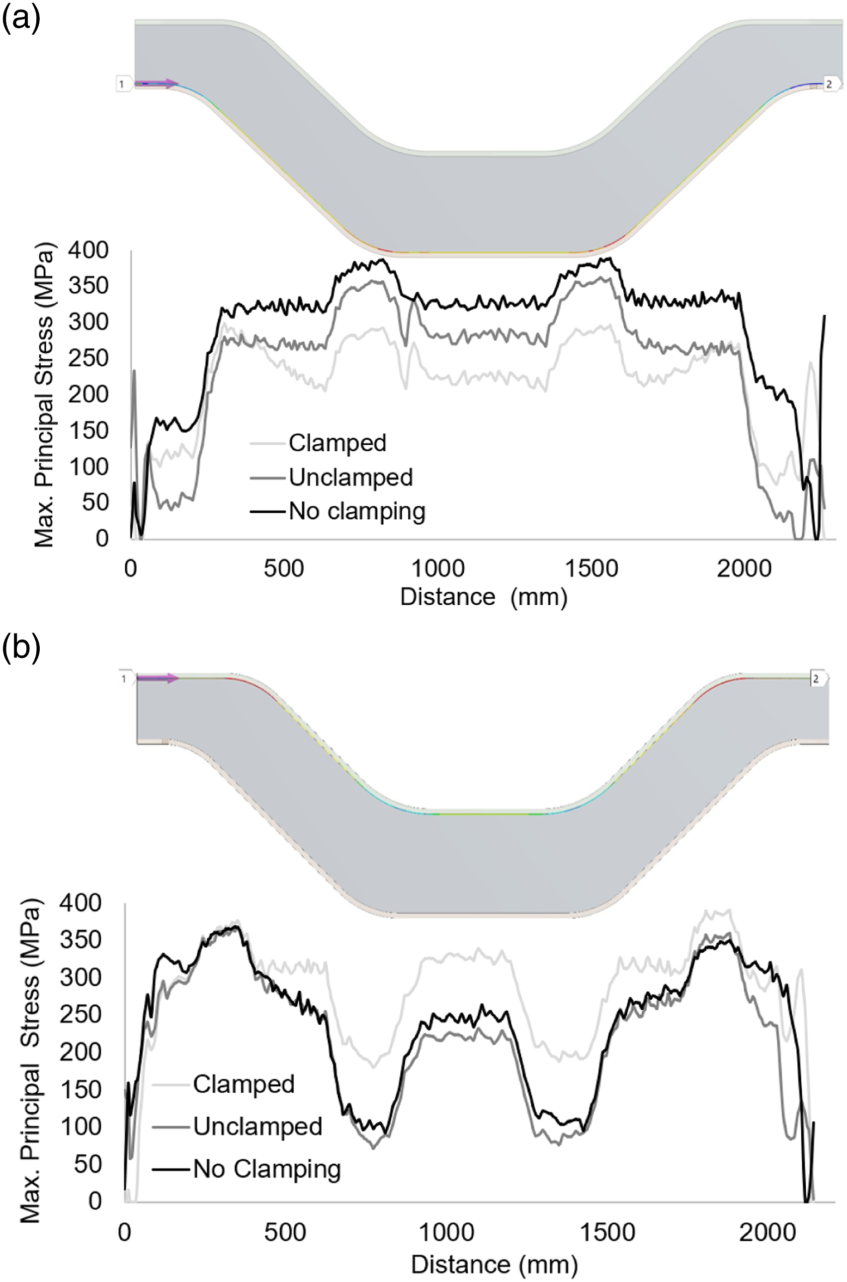
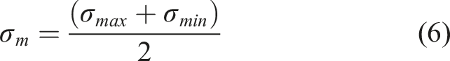
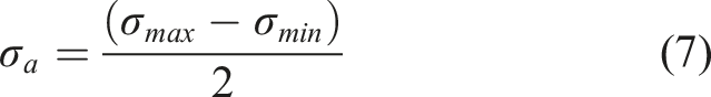
Figure 5 shows the development of the clamping force during the welding for a plate thickness of 16 mm. It can be seen that the forces in the longitudinal direction are the dominant ones. This is due to the greater residual stresses build up in the longitudinal direction. The reaction forces in the longitudinal direction increase by welding more material due to the increase of the induced residual stresses in the bogie frame side beam. Figure 6 shows the effect of the plate thickness on the build up of the reaction/clamping forces in the longitudinal direction. As expected, the reaction forces increase with increasing plate thickness. It could be quantified that the increase of the reaction forces is linear to the thickness. For instance, by doubling the plate thickness, the reaction forces in the longitudinal direction double too. The predicted reaction forces could be used for the design of jigs and fixtures. Predicted directional reaction forces for a plate thickness of 16 mm. Predicted longitudinal reaction forces for plate thickness of 12, 16, 20 and 24 mm.
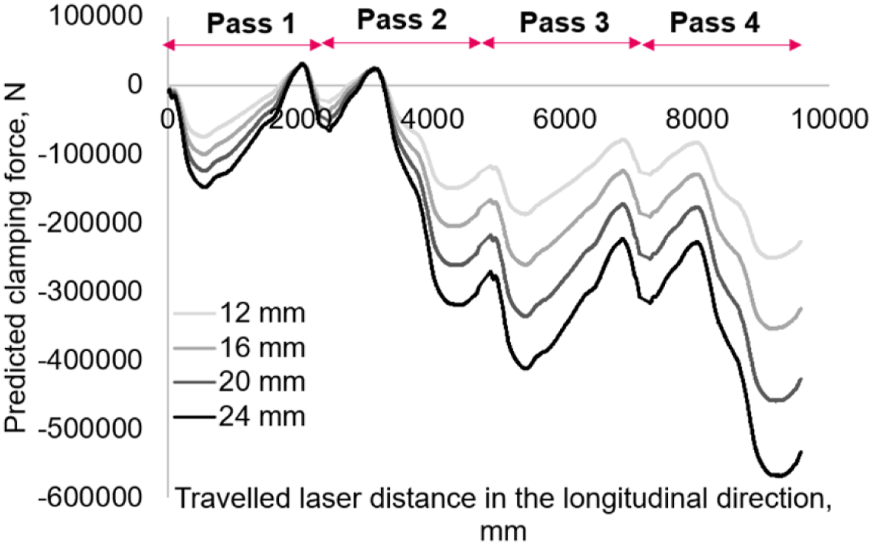
Figure 7 shows the predicted deformations in the longitudinal direction for unclamped and no clamping conditions. The two scenarios represent the two extreme conditions of a clamping system where the structure is rigidly held or free to move. In manufacturing, the clamping system will represent some stiffness in the clamped area. The results show that if the two ends of the bogie frame are rigidly held and then unclamped, the distortion would be approximately 0.5 mm less compared to the scenario where free movement is allowing (no clamping). This is a reduction from 2 mm to 1.5 mm for 24 mm thick plates. Compared to the overall length of the bogie frame of 2260 mm, the induced distortions with and without clamping could be considered negligible. Predicted distortion in the longitudinal direction.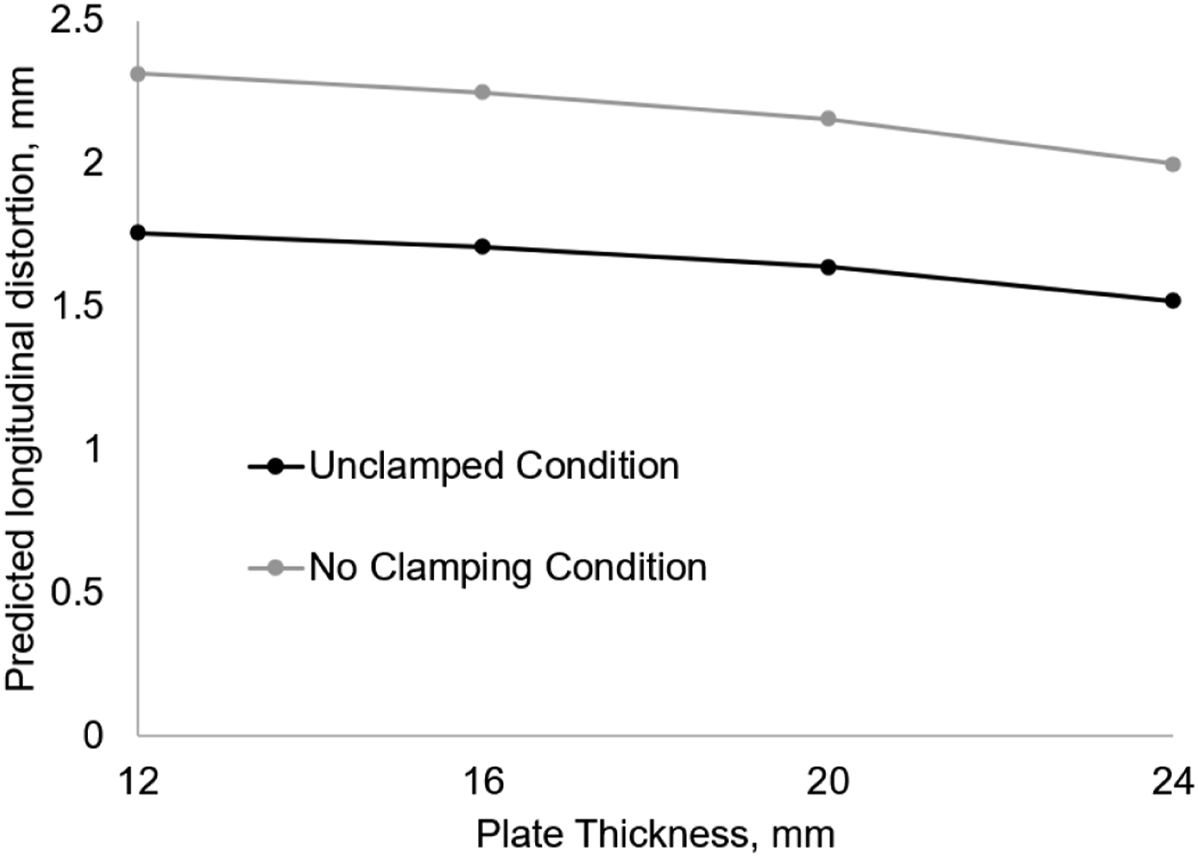
From manufacturability point of view, the clamping system could be designed to allow sliding in the longitudinal direction. This would reduce the high forces in the longitudinal direction and will not affect the overall deformations of the bogie frame side beam, neither it will have significant effect on the distribution and magnitude of the residual stresses. This would also require less comprehensive jig design capable of withstanding high forces.
Prediction of fatigue S-N curves
The proposed fatigue model is used to compare the results with BS7608, a standard used for fatigue assessment of welded steel structures, including bogie frames in the railway industry.
2
The fatigue tests in BS7608 are conducted at stress ratio of R = 0, therefore, the same stress ratio was used in the fatigue model in order to compare the proposed model with BS7608. The welds in the bogie frame can be classified as class F (full penetration butt welds) or class F2 (partial penetration butt welds). These are the two most widely applied weld types in bogie frame side beams. The proposed fatigue model is utilised applying a yield strength of 470 MPa, a surface factor of 0.8, a stress ratio R = 0 and a constant residual stress of 355 MPa representing the peak maximum predicted stresses which are close to the yield stress of the material. The obtained constants A and n for equation (15) are 10,438 and −0.364 respectively. The S-N curves for these two weld types are given in Figure 8. The results show that the proposed fatigue model predicts a S-N curve which is positioned between the S-N curves for weld classes F and F2 of BS7608. This comparison verifies that the proposed model is representative, and it can be further utilised to understand the effect of the residual stresses on the fatigue limit at 107 cycles in the welds. Predicted S-N curve and comparison with weld classes F and F2 from BS7608.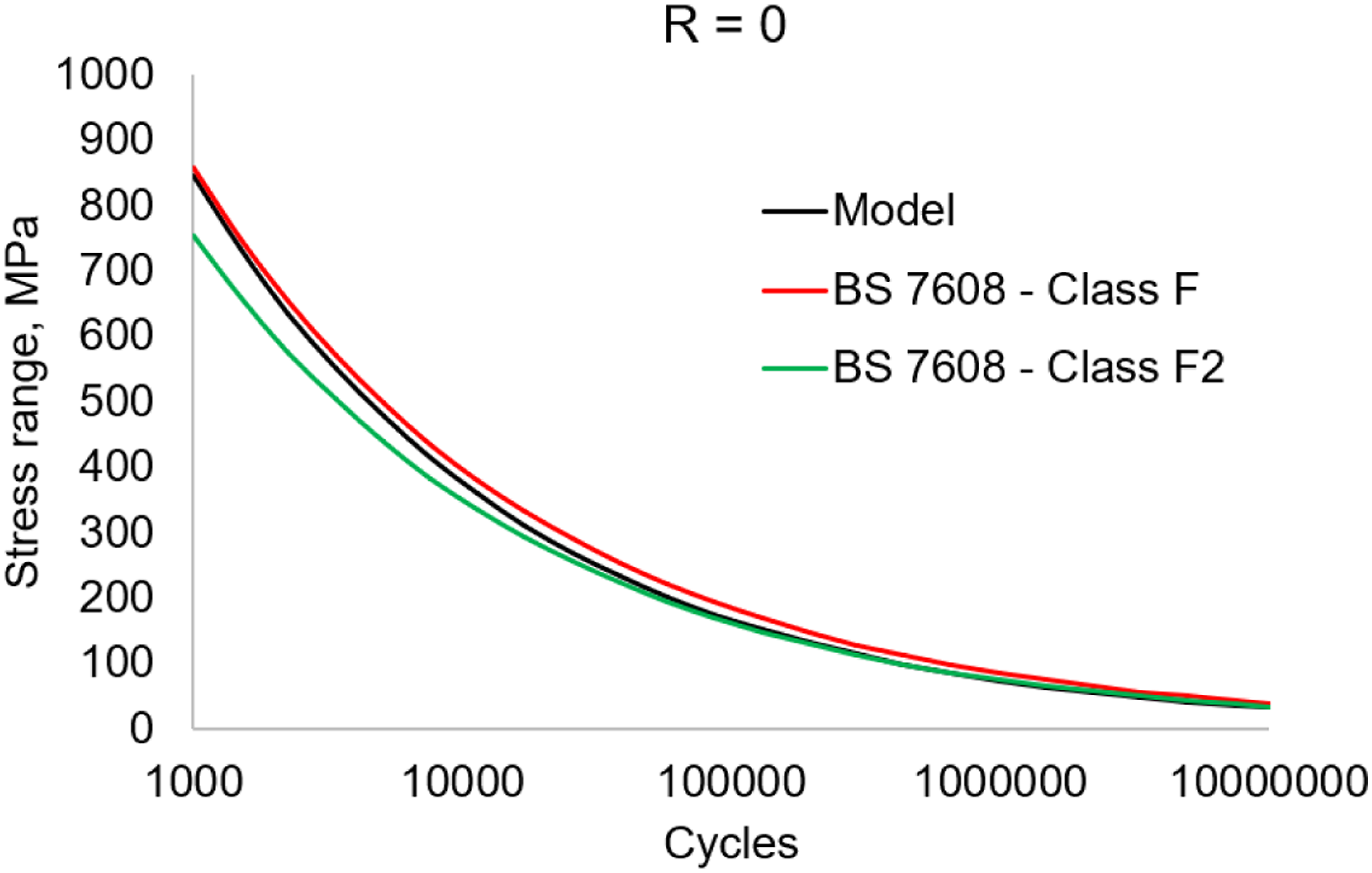
Using the predicted maximum principal residual stresses from Figure 4, the S-N curve can be predicted for each point of the welds. Using the predicted residual stresses for the unclamped condition, Figures 9(a) and (b) show the predicted fatigue limits at 107 cycles for the bottom and top welds for four thicknesses respectively. The two figures also show the fatigue limits for class F (40 MPa) and class F2 (35 MPa) welds from BS7608. It can be seen that the lowest fatigue limits are at the welds where geometrical curvatures are used in the design of the bogie frame side beam. These are the areas where the higher residual stresses were also predicted. Comparing the minimum predicted fatigue limits, we can see that by increasing the plate thickness, the fatigue limits improve. For instance, the fatigue limit for 24 mm thick plates is above 35 MPa while for 12 mm is below 20 MPa at the top weld. Another observation is that the proposed model can provide better understanding on the fatigue limits rather that using a fixed fatigue limit or fixed S-N curve. From design point of view, the provided fatigue model could inform designers and structural engineers how best to design a bogie frame. For instance, for vertical loads, the greatest stresses are at the middle of the bogie frame in the longitudinal direction. Based on the presented results, BS7608 would be more conservative than the proposed model at the middle of the bogie frame. Another point that can be made from the results is that the fatigue limits in some locations are greater than 100 MPa indicating that welds can withstand high stresses induced by in-service loads. Predicted fatigue limits after unclamping at the: (a) bottom weld; (b) top weld.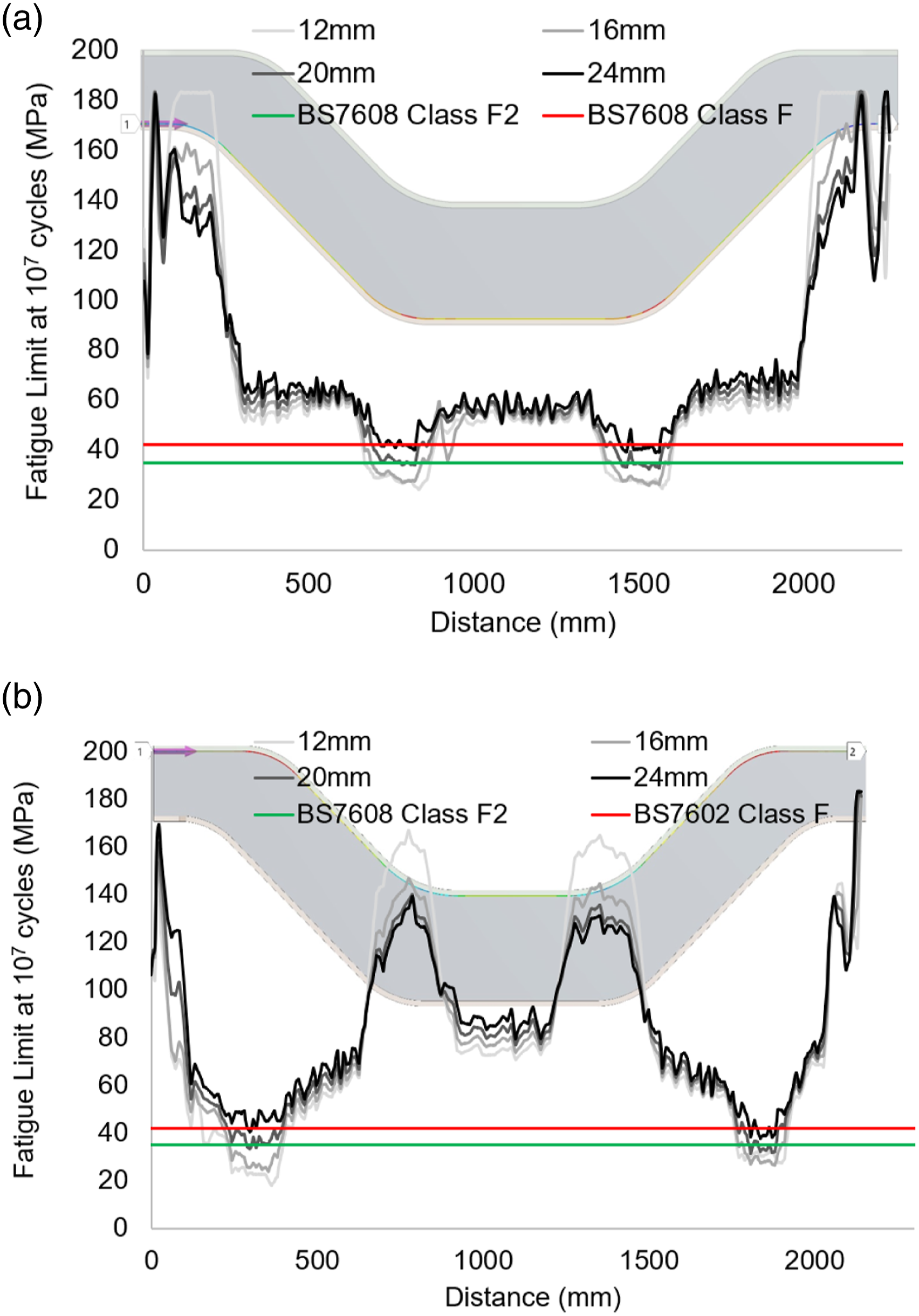
In practice, when the bogie frames are manufactured, they are also stretched where the residual stresses are redistributed, and in some locations the residual stresses are relieved. This step has not been simulated in this study, but it is possible to include following processes after the welding simulation.
Conclusion
The following conclusions were derived from this research work: - A hybrid model using analytical temperature field coupled with non-linear structural finite element model was developed and applied to welding simulation of large structures. The model showed that it can be applied to shell elements and deliver a computationally efficient simulation. - A new fatigue model based on the endurance limit approach that takes into account the residual stresses was proposed and applied to predict the fatigue limits along the welds of a bogie frame side beam. The model was verified against the BS7608 standard by comparing S-N curves. The fatigue model was applied to understand the impact of residual stresses on the fatigue limit. It was found that the model is capable of providing more detailed information for the fatigue limits along the welds instead of using a constant fatigue limit. - The predicted clamping forces and deformations showed that the proposed welding model is capable of informing manufacturing engineers how to best design and optimise clamping systems. - The welding and fatigue models were applied to understand the manufacturability and design against fatigue of a bogie frame side beam. It was found that it would be beneficial if the clamping system allows sliding in the longitudinal direction where lower reaction forces would be generated and the deformation in the longitudinal direction will be just 0.5 mm greater, which is negligible considering the large overall dimensions of the bogie frame side beam.
As a future work, the proposed fatigue model for prediction of S-N curves is intended to be applied for the full fatigue analyses of a bogie frame and compare it with current industrial practices using fatigue codes for welded steel structures (e.g. BS7608, Eurocode).
Footnotes
Declaration of Conflicting Interests
The author(s) declared no potential conflicts of interest with respect to the research, authorship, and/or publication of this article.
Funding
The author(s) received no financial support for the research, authorship, and/or publication of this article.