
Abstract
Rail vehicle lightweighting using fibre reinforced polymer composite materials is essential for the future of rail. This is recognised as a means of reducing carbon dioxide production through lower energy consumption, as well as reducing the impact on track degradation, thus delivering improved rail capacity and performance. This paper presents an overview of the work conducted within work package three of the NEXTGEAR project focused on the ‘wheelset of the future’. Three concepts for a hybrid metallic-composite railway axle are proposed and their strengths and weaknesses are assessed. A finite element analysis on the selected concept was conducted, including a solution for the bonded joints of the metallic collars which provide the interface to the wheels and bearings. An axle mass reduction of over 63% was shown. An overview is also provided regarding the analysis of manufacturability of the axle, non-destructive methods for axle inspection/structural health monitoring and effects of impacts from ballast stones. Finally, a preliminary evaluation of the benefits arising from the reduction of the unsprung masses is provided, based on multibody simulations of vehicle dynamics.
Keywords
Introduction
Lightweighting of railway vehicles is a key challenge for the rail industry. Of particular importance is the reduction of the unsprung masses, that is, the mass of bodies below the primary suspension. The dynamic effects associated with the sprung masses (such as bogie frames and car bodies) can be mitigated through the design of the suspension system of the vehicle. However, inertial effects arising in the unsprung masses (among which the wheelsets) are directly transferred to the track, resulting in large dynamic forces being applied to the track. Accelerated damage and degradation of the track system results in different forms: rolling contact fatigue damage of the rails, degradation of the geometric quality of the track and localised damage at level crossing panels. Furthermore, the reduction of the unsprung masses is also advisable in view of reducing vibration and noise emitted by the vehicles, thereby mitigating the environmental impact of railways.
The largest part of the unsprung mass is represented by the wheelsets. Therefore, in order to achieve a significant reduction of the unsprung masses, a radical re-thinking of the conventional wheelset design is required. Given that wheelsets are safety critical components, their metallic design has been approached quite conservatively in the past. However, recent research within the aerospace and automotive industries has shown the viability and benefits of the use of fibre reinforced polymer (FRP) composite materials.
The project NEXTGEAR, funded by the European Commission, aims to develop new technological concepts towards the next generation of railway rolling stock. 1 In this context, work package three ‘wheelset of the future’ investigated the feasibility of using fibre reinforced polymer (FRP) composite materials for the construction of a lightweight hybrid metallic-composite (HMC) wheelset. After initial examination, the focus became the design of a wheelset with a composite axle and conventional steel wheels. This design provides an efficient and safe method to integrate the braking function (using disk brakes with wheel-mounted disks), ensures alignment of the wheels to the track and simplifies the metallic-to-composite joining.
A few examples of concept hybrid metal-composite axles can be found in the literature: British Rail investigated the use of carbon fibre reinforced polymer (CFRP) composites for railway axles as part of the development of the advanced passenger train (APT), 2 but there was no follow-up of this attempt. More recently, the potential for lightweighting a railway axle was investigated by Mistry and Johnson, 3 considering an increase of the outer diameter of the axle and of the inner diameter of the bore, in combination with the use of FRP composites. Potential mass savings of up to 84% were calculated. However, the FRP materials considered are prohibitively expensive and the increase of the outer diameter of the axle impacts heavily on the design of the running gear, particularly the bearings.
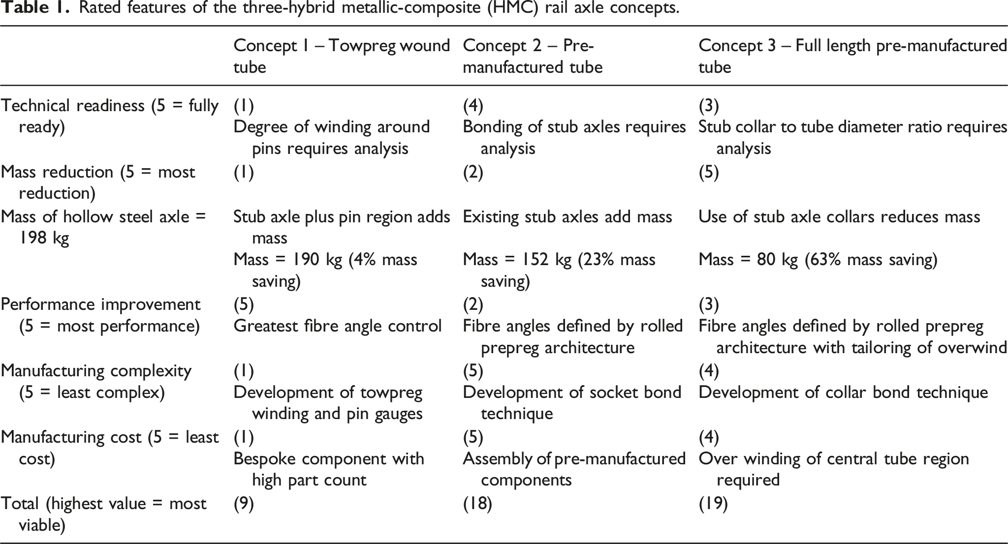
Within NEXTGEAR, an axle for an inboard bearing trailer wheelset for use in metro vehicles was used as a case study (hollow steel axle of EA1N grade steel with a mass of 198 kg). Three concepts for a HMC axle were defined and prioritised in regard of their structural performance, mass reduction, manufacturing complexity and cost. One of the three concepts was chosen for further development (see Figure 1) to address a number of interrelating research topics including: 1. Structural design; 2. Design of composite-to-metallic adhesive joints; 3. The effect of impact with ballast stones; 4. Techniques for non-destructive testing (NDT) and structural health monitoring (SHM) of the axle; 5. The benefits of a lightweight axle in terms of reduced train-track interaction forces; The full length pre-manufactured tube axle design concept annotated with the five key areas of research covered by the NEXTGEAR ‘wheelset of the future’ work package.
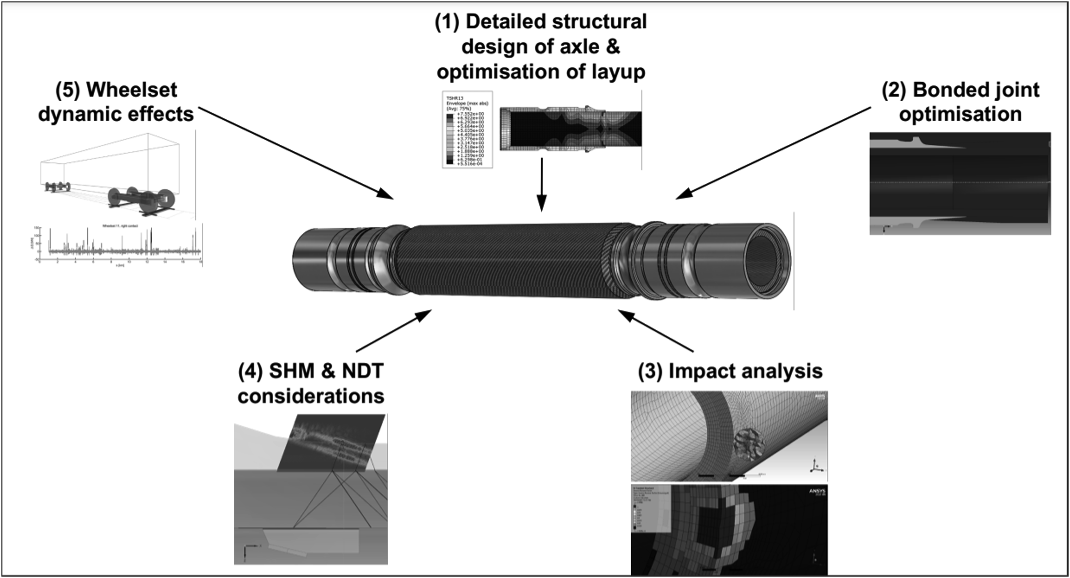
The aim of this paper is to present the advancements in these topics towards the development of a HMC railway axle.
Initial design concepts
The composite railway axle design concepts rely on carbon fibre as the reinforcing structural material with epoxy resin as the binding matrix. This combination provides good reliability for this fatigue-driven design. The distinction between concepts is largely dictated by the manufacturing method employed. The materials and manufacturing techniques are established technology.
Concept 1 – towpreg wound tube axle
The concept of the towpreg wound tube axle is shown in Figure 2(a). This concept relies on the bespoke production of the fibre reinforced tube that is wound onto a pre-manufactured mandrel incorporating the stub axles. Winding the towpreg around the 12 evenly spaced pins integrated into the stub axles allows for complex fibre orientations to be easily prescribed for each layer.
4
Mixed fibre combinations, for example, carbon and glass, could be wound either on a single layer or on overlapping layers to meet cost or performance objectives. The winding process would enable hoop wound fibres to be placed at either end to reinforce locally the inserted stub axles. Towpreg represents one of the lowest cost formats for the fibre to be purchased while the pre-impregnated fibre would provide a consistent, repeatable composite tube.
5
As the tube is wound to a net shape, material waste is minimal. Once the wound tube is autoclave cured, no further processing of the composite would be required. Thus, the rationale for this concept is to provide the greatest flexibility in the composite lay up for performance improvement at a low manufacturing cost. This concept has a mass of 190 kg which is a 4% mass savings compared to the original steel axle. The three concepts of the hybrid metallic-composite (HMC) axle: (a) towpreg wound tube, (b) pre-manufactured tube and (c) full length pre-manufactured tube.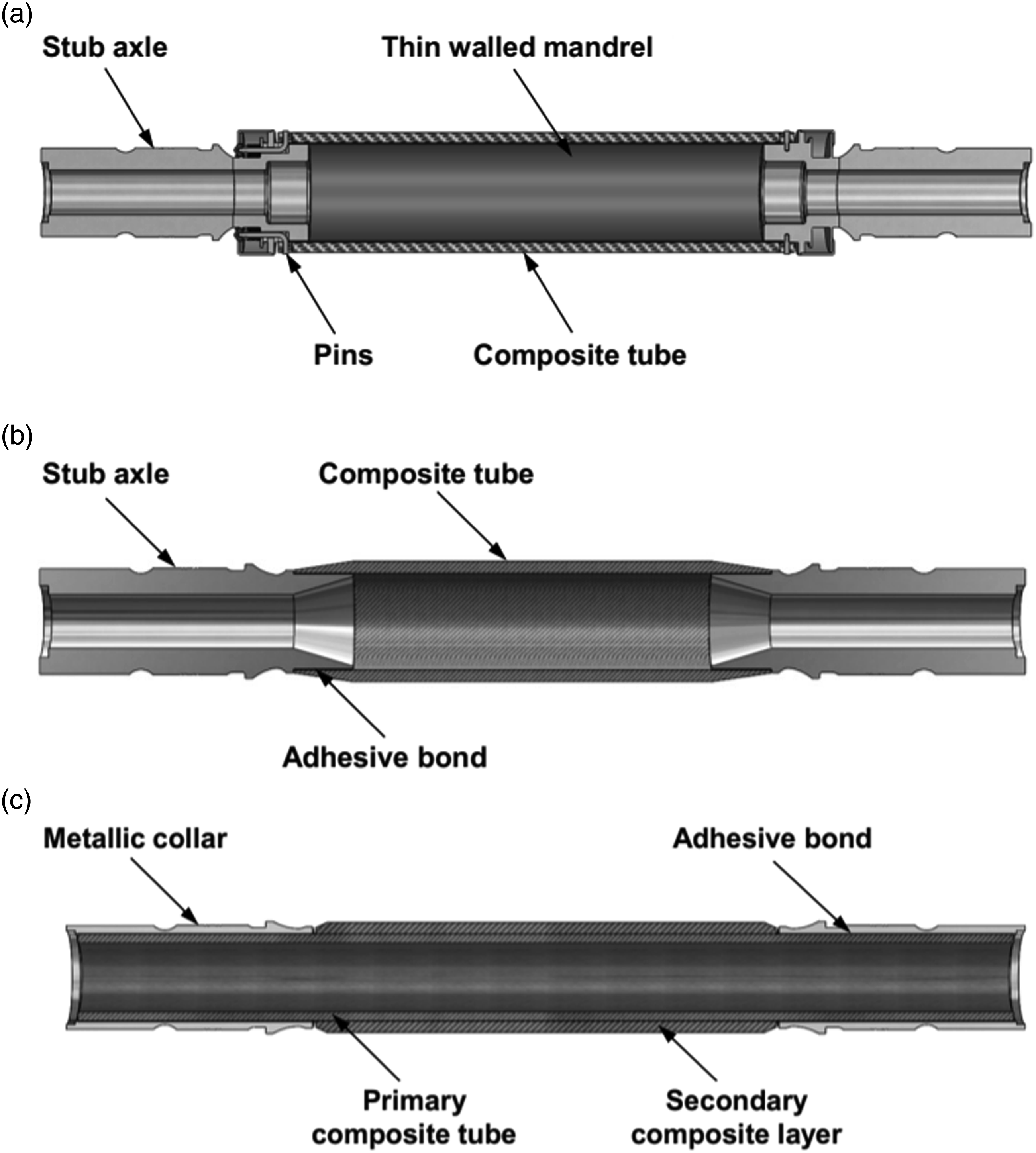
Concept 2 – pre-manufactured tube axle
The concept of the pre-manufactured tube axle is illustrated in Figure 2(b). The pre-manufactured composite tube axle concept relies on the offline production of a carbon fibre epoxy composite tube that can be cut to length and used as a component of the final axle assembly. Roll wrapping of prepreg is a likely manufacturing process for the tube. 4 Stub axles are bonded into each end of the tube. The rationale is that a long tube, ideally produced by continuous manufacture, would be the most cost-efficient means of introducing the light weight, tubular structure. This concept has a mass of 152 kg which is a 23% mass saving compared to the original steel axle.
Concept 3 – full length pre-manufactured tube axle
The concept of the full-length pre-manufactured tube axle is illustrated in Figure 2(c). The primary composite tube spans the entire length of the axle. As for concept 2, roll wrapping is a possible manufacturing route for the tube. Either end of the composite tube would be fitted with identical, adhesively bonded, thin-walled metallic collars for mounting of the inboard bearings and wheels.
The central region of the axle has a secondary composite tube roll wrapped over the primary composite tube to increase the axle diameter up to a thickness sufficient to support the loading requirements. The rationale of this concept is to minimise the mass of the assembly. This concept has a mass of 80 kg which is a 63% mass saving compared to the original steel axle.
Summary of composite railway axle design concepts
Rated features of the three-hybrid metallic-composite (HMC) rail axle concepts.
Proposed hybrid metallic-composite railway axle design
The final design and composite layup of the selected HMC railway axle that evolved from concept 3 was the subject of parametric study carried out by Mistry et al.
6
and the final solution is shown in Figure 3. The design is based on the procedure set out in the Standard BS 8535.
7
The primary and secondary composite tubes are made from a high modulus CFRP epoxy, unidirectional prepreg, while the collars are EA1N grade steel. This axle has a final mass of 74 kg, representing a mass reduction of 63% compared to the equivalent hollow steel axle at 198 kg. Final design of the hybrid metal-composite (HMC) railway axle with an approximate mass of 74 kg.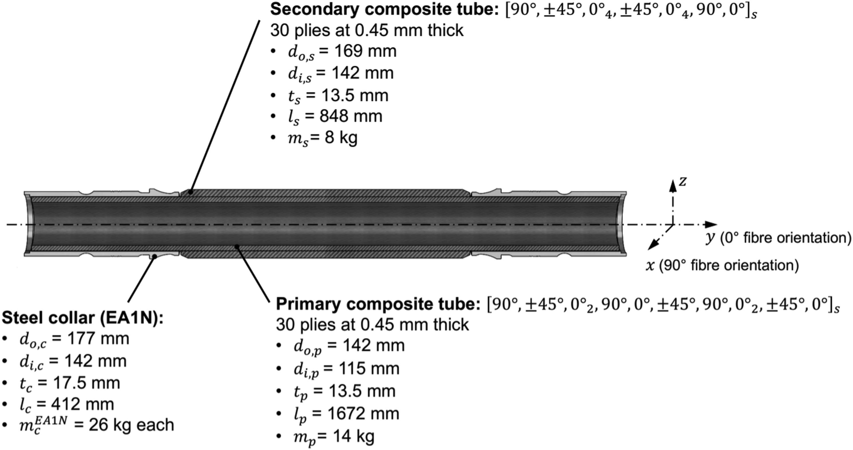
The combined loading is applied as superimposed moments representing the critical case of the ‘masses in motion’ and ‘braking’. 8 The design features EA1N grade steel collars with a wall thickness of 17.5 mm to accommodate the interference fit of the wheel without causing damage to the primary composite tube. The fibres within the primary composite tube are oriented at 90° to provide strength against the main circumferential stresses. The wall thickness of the primary composite tube is 13.5 mm for supporting the reversed bending and torsional loads. The specific number of 0° and ± 45° plies are included for this purpose. The secondary composite tube allows for tuning of the axle deflection as well as the bending and torsional frequencies. This tube is 13.5 mm thick and utilises 0° plies to restrict bending to 1.8 mm at the midspan while maintaining an increase in the back-to-back wheel distance at rail level of 3.21 mm. The first bending frequency is 389 Hz.
The primitive shape of the steel collar has the consequence of imposing a high contact stress (521 MPa) onto the outer diameter of the primary composite at the inboard end. While finite element analysis (FEA) of the axle meets the Hashin failure criterion, resolution of this high stress and the adhesive joint itself is the subject of future work.
Adhesive-bonded joint design
The viability of a HMC railway axle design (Figure 4) relied upon the identification of a solution for joining the metallic collars to the primary composite tube. Adhesive bonding is particularly suitable for joining dissimilar materials without adding significant weight (compared to mechanical joints), achieving good fatigue resistance and providing design flexibility.9–14 Nevertheless, joining multi-materials can be challenging. For this application, the mechanical behaviour under fatigue loading and the environmental resistance of adhesive joints needs to be studied in order to guarantee safety and reliability.15,16 A preliminary assessment of the adhesive joint between the metallic collar and the composite tube of concept 3 was conducted based on local stress analysis, which eventually led to the proposal of an improved joint configuration. The finite element model of: (a) the connection between the metallic collar and the composite tubes and (b) the improved bevel joint between the metallic collar and the composite tube.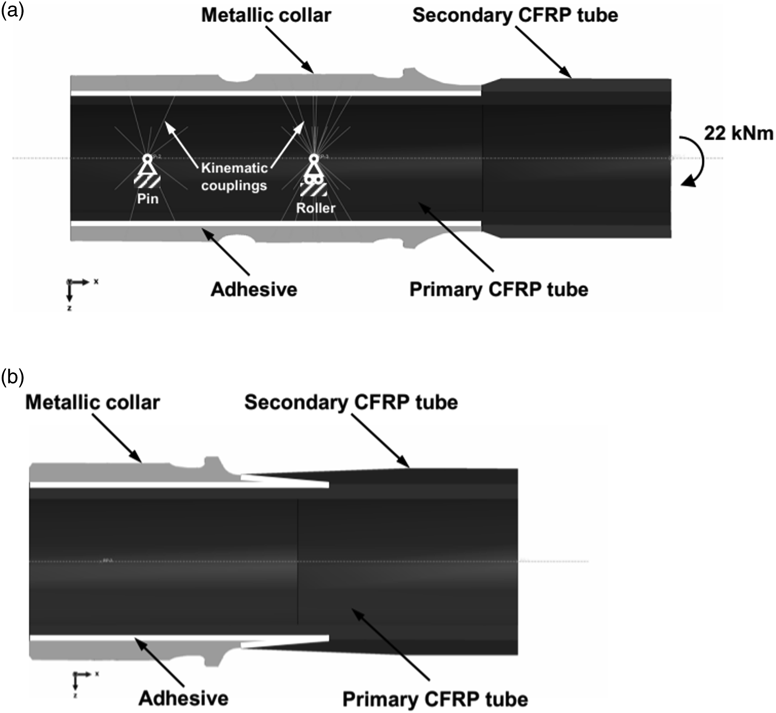
The evaluation of the local stresses in the adhesive layer was conducted by finite element (FE) analysis using Abaqus CAE software. 17 Stress analysis in the bondline was conducted with reference to the properties of the 3M 9323 B/A adhesive, 18 which was selected as representative of a typical epoxy paste adhesive often employed for structural bonding. The choice was motivated by the availability of the results of an extensive characterisation of the fatigue behaviour of various joint types. 19 In this work, a local stress approach was presented, and it was shown that the shear stress amplitude constitutes a parameter able to correlate the fatigue lives for different joint configurations. The range of cycles previously explored 19 does not exceed one million cycles, therefore an extrapolation was needed to obtain an admissible shear stress amplitude for 100 million cycles, which corresponds to the service life of the wheelset. Future work should refine the choice of the adhesive and specific fatigue tests should be performed, including the assessment of the environmental conditions. Additional tests were performed to measure a critical strain energy under mode I loading of 2.8 N/mm.
A FE sub-model of the collar and the tubes was created, as depicted in Figure 4. Boundary conditions of a pin and roller were applied to the reference points on the left and in the centre of Figure 4(a), which were then connected to the inner surface of the inner tube by kinematic constraints. A third kinematic constraint was placed on the right end, and it connected the end cross-section with a reference point, where a bending moment of 22 kNm was applied. The composite laminate tubes were modelled as homogeneous orthotropic materials, homogenisation being performed analytically based on the stacking sequence presented in Figure 3 and the engineering constants reported in Appendix Table A1.
Results showed that the maximum shear stress in the adhesive layer was located at the inboard side of the overlap, between the metallic collar and the primary composite tube. Refined FEA employing cohesive elements demonstrated that under static loading (22 kNm bending moment) the adhesive would fail. Consequently, the geometry of the joint was modified, seeking to minimise the stresses in the adhesive layer. An improved geometry was obtained, consisting of a bevel joint between the outer tube and the metallic collar. The latter is joined to the primary tube by adhesive, with a tapered overlap (Figure 4(a)). The length and the angle of the bevel, and the taper were iteratively modified until the shear stresses were reduced below the limit for the design life of 100 million cycles with a probability of survival of only 50%, extrapolated from Bernasconi et al., 19 Given the uncertainty of the estimate of the fatigue strength by extrapolation over two decades, the stress reduction achieved with this geometry appears a promising solution. It is recommended that this be adopted only after an extensive characterisation of the fatigue behaviour of the chosen adhesive.
However, the challenge remains of how to manufacture this complex joint configuration for this safety critical application. A two-step procedure could be devised consisting of bonding the primary composite tube to the metallic collar and then bonding the secondary composite tube to the bevelled surface of the metallic collar. However, an improved solution would replace the second step by wrapping the secondary tube over the metallic collar, employing a film adhesive instead of the paste epoxy, and co-curing the secondary tube together with the film adhesive. However, this would expose the adhesive between the primary composite tube and the collar to a temperature which would degrade the adhesive used for the calculations. Future work will focus on the selection and the characterisation of the most appropriate adhesive to identify a safe and fully manufacturable joint.
Analysis of manufacturability
The roll wrapping (RW) process was assumed in the design phase of the HMC axle. In addition, automated fibre placement (AFP) was also considered, because it is an automated process that could achieve the volume production required. Roll wrapping provides the capability to allow the stacking sequence to be customised as opposed to AFP, because it allows the placing of layers with fibres perfectly aligned with the tube axis. However, manually placing the prepreg plies will inescapably generate a butt joint for each layer longitudinally to the axis of the tube, resulting in a fibre discontinuity for each layer of the tube.
Conversely, if AFP is chosen and combined with deposition on a rotating cylindrical mandrel, such as in filament winding, fibres cannot be placed at an angle less than 10° with respect to the tube axis.
Manufacturing by RW and AFP would result in a different layups and therefore dedicated analyses were carried out to compare the two methods. The study aimed to verify if a prescribed improved stacking sequence could be obtained by both AFP and RW that would result in the same structural performance. In addition, the mass of the manufactured tubes was to be evaluated to compare the two processes.
The following points were considered when developing the best stacking sequence that can be manufactured by AFP: • Re-orientation of plies, previously oriented at 0° in the RW axle, to ±10° is required; • Introduction of orientation-dependant minimum ply thickness; • Estimation of the effect of the winding pattern on the composite stiffness; • Determination of engineering constants in the principal material directions generated by the AFP process;
Separate primary and secondary tubes were modelled in a simplified bending/torsion loading condition and a FE based optimisation procedure for the layup was defined. This procedure searched for the minimum mass solution that satisfied the constraint condition that their maximum static displacement and rotation were lower than or equal to those of the corresponding roll wrapped counterparts. Software packages Hyperworks 20 and Optistruct 21 were used for modelling and solving the optimisation steps, respectively.
To account for the possible detrimental effect of fibre interweaving induced by AFP, knock down (KD) factors for torsional and bending stiffness were introduced. This resulted in constraints that were more stringent than the original target values.
Their estimation required an iterative process because their values depend on the actual stacking sequence at each iteration. The values at the first iteration were set to 1 (i.e. no effect on stiffness). Then, an optimum layup was obtained by the FE based optimisation procedure. In the subsequent iterations, KD factors were updated, based on the results of the simulation of the AFP process using Cadwind software, 22 which allows consideration of the material orientation variations due to fibres intertwining. The results from the AFP process yielded a different superposition of fibres and different thickness for each ply.
The material properties adopted for modelling the tube manufactured by AFP refer to a towpreg material having the following properties: • Flame retardant resin system; • Tape width of 6 mm; • 24 K carbon fibres; • Fibre mass content: 67%; • TEX (a measure of the weight of fibre per unit length): 1600 g/km;
At each iteration, the AFP process was simulated, and the results (material orientation, engineering constants, ply thicknesses for each finite element) exported to a FE model to analyse the primary and secondary tubes under the reference loading conditions. The KD factors were evaluated by comparing the performance of the model exported from the AFP simulator with another one, identical in terms of geometry, mesh and loading conditions but with thickness and material orientation assigned like a classical composite laminate. This model did not consider fibre intertwining.
Then the updated KD factors were attributed to the allowable deformation values for the next iteration, to update the design constraints, reducing the absolute values of the allowable deflection and rotations. The procedure was stopped when two subsequent iterations provided the same output result, and also when two identical stacking sequences for the optimised AFP tubes were found. At the end of the optimisation routine, the following equivalent stacking sequence for AFP was derived. The stacking sequences for the composite tubes using conventional layup code notion:
23
• Primary tube: • Secondary tube:
Comparison of the outcomes in using Roll Wrapping (RW) or Automated Fibre Placement (AFP) to manufacture the HMC axle.
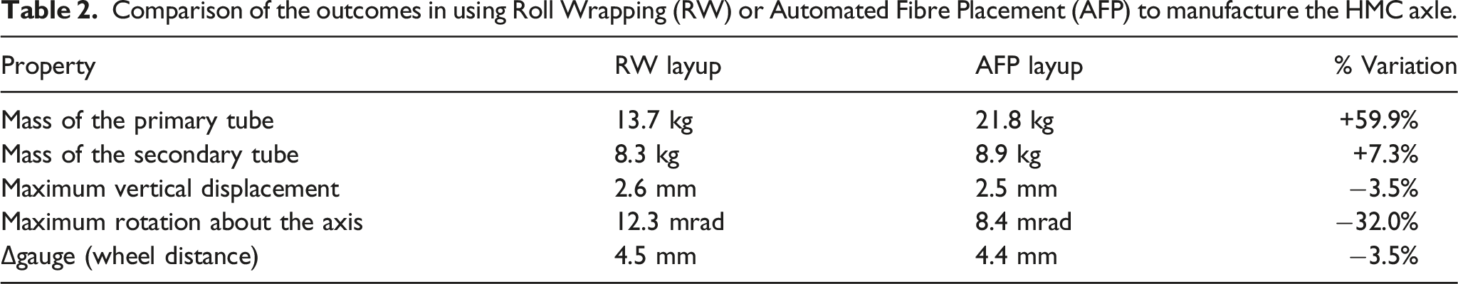
If the axle was to be manufactured by AFP, the mass of the primary tube would increase by 8.18 kg. However, the mass of the secondary tube would remain almost unaffected. However, the assembly of primary and secondary tube would result in lower vertical displacement and a decrease of the rotation about the axis due to torsion. As for RW, the effect of the presence of butt joints was not accounted for in the analysis and it would require further experimental testing. The AFP generates a pre-tension in the fibres whose effect is not included in the presented simulation, and which can be relevant for the overall elastic behaviour of the axle. Indeed, a more accurate conclusion on the expected mechanical behaviour of the concurrent design (RW and AFP) solutions could be drawn only after experimental validation on coupon specimens of the mechanical properties assumed in the models.
From a manufacturing point of view, it is envisaged that the AFP process would allow for increased repeatability of the final product as it is an automated process.
Non-destructive testing and structural health monitoring
In order to validate the manufacturing process and provide whole-life inspection capability, NDT and SHM are explored. The HMC axle can be divided into three main constituent regions: 1. The central region, characterised by the superposition of the coaxial primary and secondary composite tubes; 2. Two lateral regions, characterised by the inner (primary) CFRP tube and by the outer metallic collar bonded together by an epoxy adhesive; 3. The bonded joint located between the central and lateral regions;
Each region requires specific NDT methods and procedures and, possibly, SHM approaches. During in-service maintenance, the common practice to perform NDT inspections of steel axles requires the synergic application of three different NDT methods:24,25 visual testing (VT), magnetic particle testing (MT) and ultrasonic testing (UT).
Regarding VT for the HMC axle, no relevant or substantial differences are expected with respect to steel axles, but the personnel must be trained to detect the typical defects of composites and adhesive bonded joints, along with those of steel.
MT is, instead, very limited because composite parts are not ferromagnetic, so this method remains effective only for the surface of the metallic collars after disassembling wheels and axle boxes. Possible alternatives, to be studied in detail and validated by suitable experiments in future developments of the research, could be: 1. Liquid penetrant testing (PT): the inspected parts must be chemically inert with respect to the products used for inspection. Typically, it takes longer than MT and coatings of the inspection surfaces are not allowed; 2. Eddy current testing (ET): this technique was recently introduced into the relevant standards.
24
It requires an electrically conductive material. So, the applicability to the composite axle depends on the volume fraction of carbon fibres. With respect to MT and PT, the equipment is more expensive, but the procedure can be very fast and automated; 3. Tap testing is an effective and widespread technique for inspecting composite parts and coatings, so it could be applied to the composite axle. With respect to MT, PT and ET, tap testing may be the fastest and least expensive technique, albeit less sensitive;
Considering UT, a preliminary feasibility analysis was undertaken based on numerical simulations using CIVAnde software.
26
It was assumed that the HMC axle will be inspected using UT along the smooth cylindrical surface of the longitudinal bore of the axle, which is suitably regular for the application of the probes. Moreover, both perpendicular incidence of longitudinal sound waves and angled incidence of shear waves were considered in order to analyse the detection of different kinds of possible defects. Finally, the involved CFRP composite tubes were implemented as equivalent homogenised orthotropic materials having a structural attenuation coefficient equal to 0.8 dB/mm at 4 MHz. Figure 5 shows the representative results within the three regions for the case of perpendicular incidence of longitudinal waves (results on angled incidence of shear waves were conceptually analogous). Preliminary feasibility analysis, by numerical simulation, of an ultrasonic inspection of the HMC axle: (a) Sound beam shape (pressure) in the central CFRP-CFRP region, (b) Defect response at the CFRP-CFRP interface in the central region, (c) Sound beam shape (pressure) in the CFRP-steel lateral region and (d) Defect response at the CFRP-steel adhesive-bonded joint in the lateral region.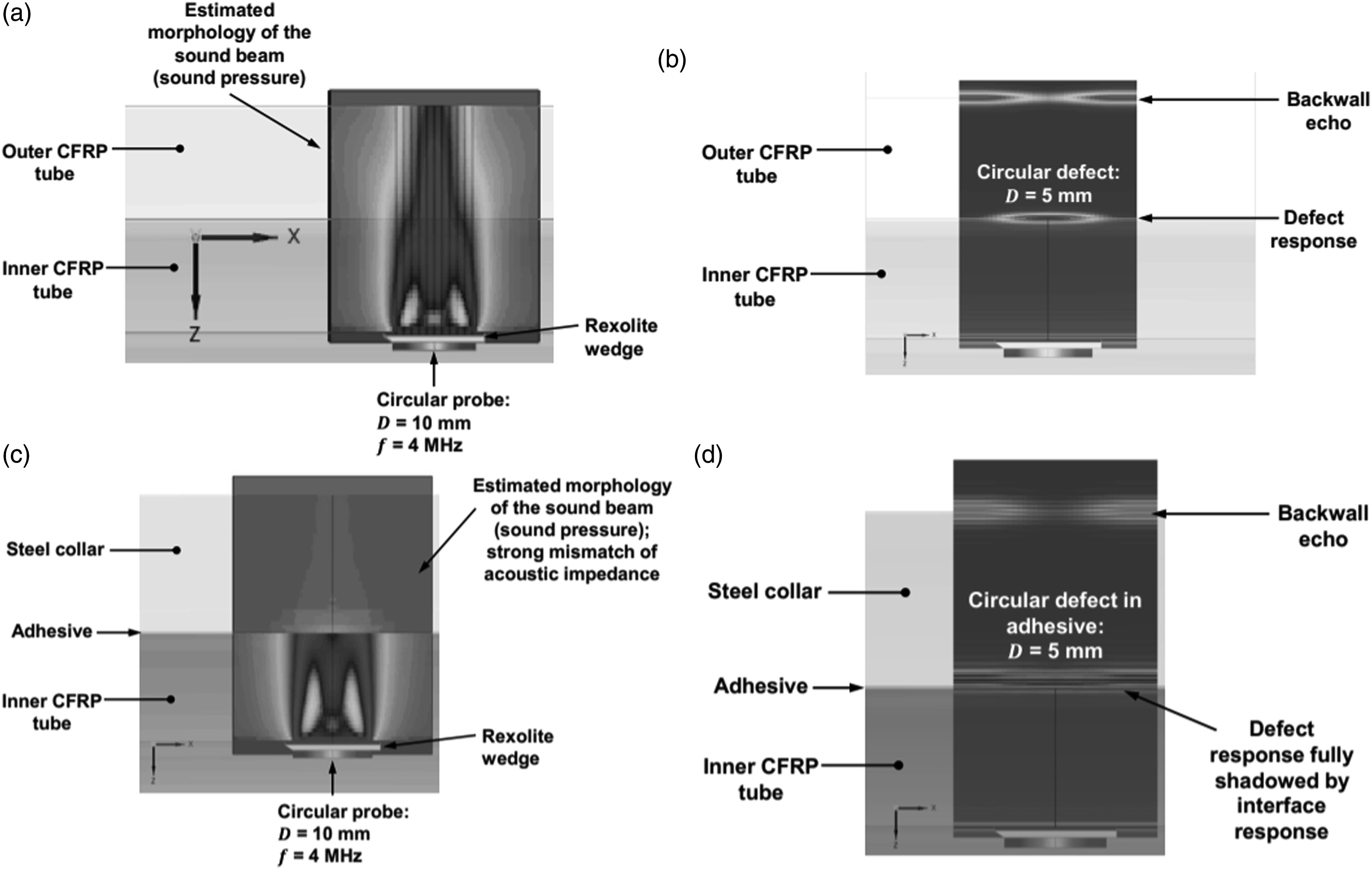
The results of the analysis demonstrated the possibility of applying UT to the central region of the axle. Figure 5(a) shows the morphology, in terms of sound pressure, of the sound beam generated through the inner and outer composite tubes, while Figure 5(b) shows the successful inspection of a circular defect (diameter equal to 5 mm) located at the interface between the two CFRP tubes. The same does not hold for the lateral region of the HMC axle: the mismatch of acoustic impedance between CFRP and steel clearly prevents an effective onset of sound pressure in the steel collar (Figure 5(c)) and produces a shadowing effect for defects located in the adhesive layer making them very difficult to be detected (Figure 5(d)). Further experimental validation of the UT method is, then, required with the definition of suitable Probability of Detection curves 27 being desirable.
In summary, NDT of the HMC railway axle may be possible using traditional techniques – if supported by less traditional methods – the reliability of the results is expected to be lower than for a steel axle. This is because MT cannot be applied systematically, and UT seems to show a lower sensitivity in the lateral region of the HMC axle.
To overcome these deficiencies, a paradigm shift to SHM was evaluated for the adhesively bonded joint between the metallic collar and the CFRP outer tube (Figure 6). The assumption was the application of a back-face strain technique (Figure 6(a)) based on optical fibres as distributed strain sensors and Optical Backscatter Reflectometry as the physical principle.
28
Preliminary feasibility analysis of a SHM approach to the composite axle: (a) suggested position for the optical fibre, (b) simulated circumferential crack in the FE model, (c) FE simulated longitudinal strain fields for varying artificial crack lengths and (d) FE simulated longitudinal strain values (E11) along the optical fibre path.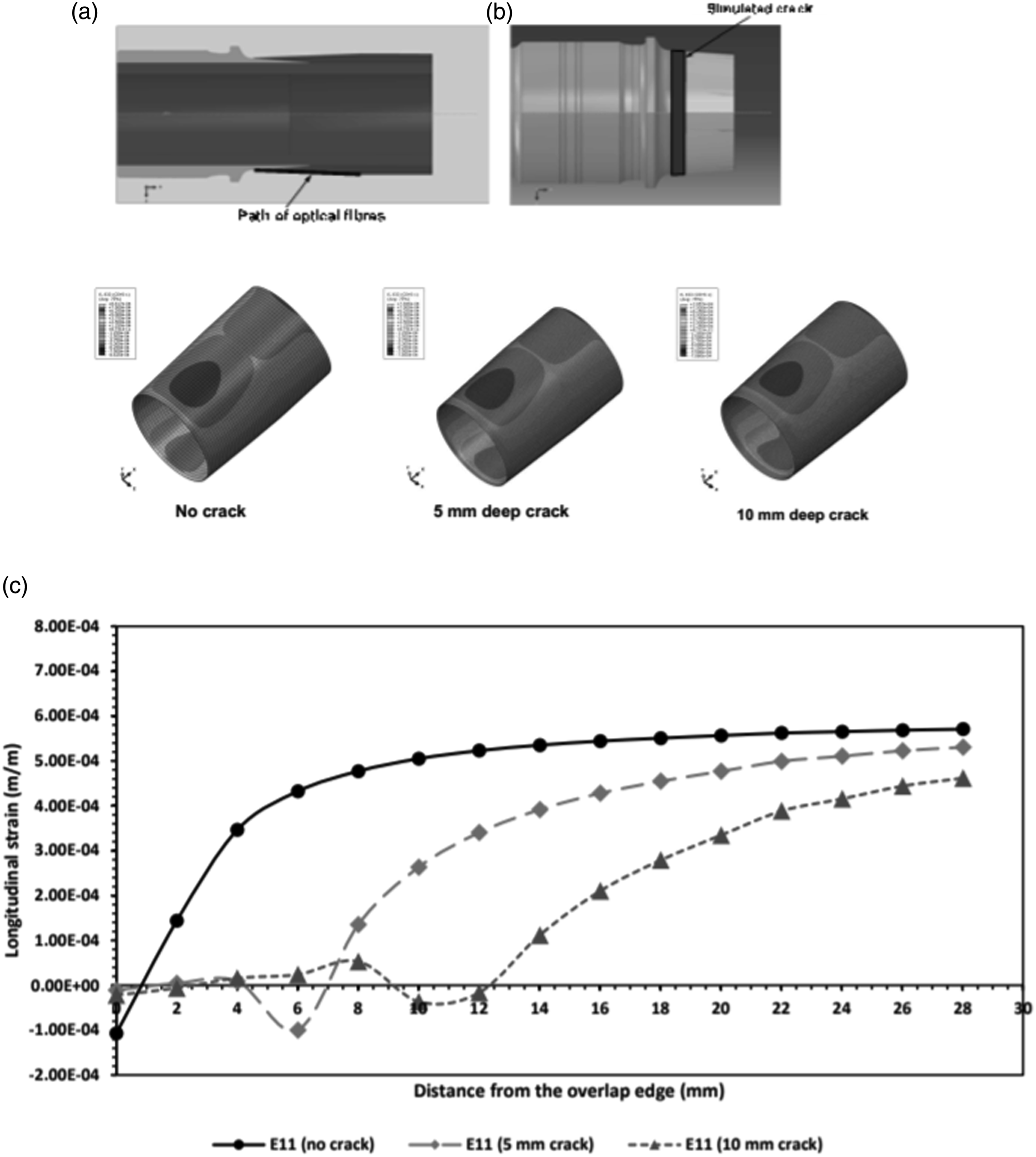
The feasibility of this approach was assessed by FE simulations of the undamaged and damaged bonded joint (Figure 6(b)). Specifically, three models were built and the corresponding strain patterns computed (Figure 6(c)), (i) pristine bondline, (ii) 5 mm deep, circumferential artificial crack and (iii) 10 mm deep, circumferential artificial crack. Figure 6(d) extracts from Figure 6(c) the trends of strains along the prospective path of the sensing optical fibre. It is evident that the morphology of such trends of strain is related to the increment of crack length, although such a relationship does not appear to be linear.
In conclusion, a SHM technique based on strain sensing constitutes a feasible solution for the considered adhesively bonded joint, but experimental validation is still required. This strain sensing would not have to be continuous but instead could be performed at regular intervals ‘on demand’. The periodicity should be determined on the basis of the fatigue crack growth behaviour of the bonded joints, that still needs to be investigated.
Impact analysis of composite laminates
Impact of stones raised from the ballast during the passage of the train represents a particularly severe condition for the axle design. The Standard EN 13,261 29 defines axle characteristics, qualification procedures and delivery conditions of axles for use on European networks. The impact test conditions are described in Annex C of the Standard. The requirement is to fire a steel projectile (diameter: 32 mm, top angle: 105°, mass: 60 g, Vickers hardness: 400, exit speed: 19.4 m/s) perpendicular to a specimen of the axle, possibly covered by a protective coating.
A numerical model able to reproduce the abovementioned test procedure is set up using the Ansys Workbench, 30 with the adoption of the Ansys Composite PrepPost (ACP) tool for the definition of the ply stacking sequence of the primary and secondary composite tubes.
The numerical model comprises the following components: • The axle, made of two concentric composite tubes and two steel collars at either end; • The spherical projectile impacting the axle in the middle;
Analyses are focused on investigating the behaviour of the composite components, therefore, the steel collars are simplified as cylindrical components. The projectile is considered spherical with diameter equal to 32 mm. To increase computational efficiency while maintaining adequate accuracy of results, the solid mesh is generated as follows: • Primary tube: five plies for each mesh layer, single mesh layer thickness equal to 2.25 mm, six mesh layers in total; • Secondary tube: three plies for each mesh layer, single mesh layer thickness equal to 1.35 mm, 10 mesh layers in total;
Hexahedral linear elements are adopted for meshing both the composite tubes and the collars, while the spherical projectile is discretised by tetrahedrons only. A gradual element refinement, from the ends to the centre of the axle, where the impact with the projectile occurs, is implemented. Elements having an average longitudinal size of 10 mm are used in the region far from the impact area, while element size is reduced to 3 mm in the impact area. The sphere is discretised by 3 mm tetrahedrons. The total number of elements is approximately 1.5 million.
The following assumptions are made: • General joints are applied to constrain the collars to the ground, leaving only the rotations along the vertical axis free; • Bonded contacts are applied between the metal collars and the composite tube as well as between primary and secondary tubes; • Simple frictionless contact is applied between the secondary tube and the spherical projectile;
Two analyses are performed to evaluate sensitivity to the impact angle, namely: • Analysis 1: A spherical projectile is directed normal to the axle surface, with an initial velocity of 19.4 m/s, as described in Annex C.4 of EN 13,261:2009+A1;
29
• Analysis 2: Analogous to analysis 1, except that the spherical projectile impacts onto the axle at a 45° angle with respect to the axle surface
To evaluate the occurrence of a failure in the composite material, the Hashin failure criterion is adopted. This is capable of identifying the presence of fibre failure, matrix failure and delamination.
Figure 7 illustrates the behaviour of the system in terms of damaged elements, for an impact angle equal to 90° (Analysis 1 – Figure 7(a)) and 45° (Analysis 2 – Figure 7(b)). The colour scale corresponds to a damage parameter which defines whether the composite layers present failure. Damage plot near the impacted region (section view) of the axle: (a) impact angle at 90° and (b) impact angle at 45°.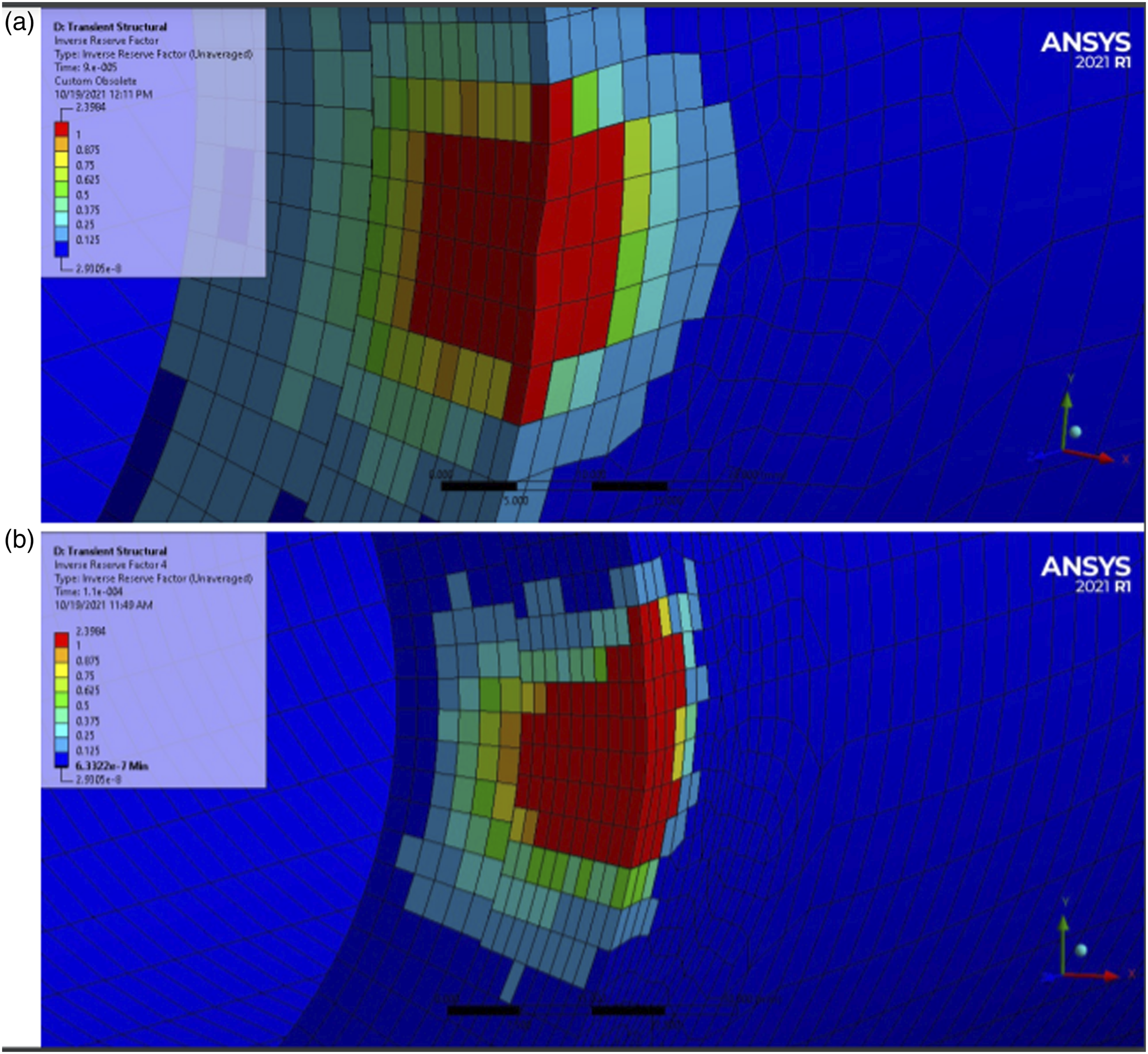
The red areas correspond to elements with a value higher than one and are critical from the point of view of the structural performance. These regions require further investigation. For red coloured elements, ACP provides information about the abovementioned failure criteria and the ply number (in parenthesis) for each element which is subject to failure.
For both impact angles, damage occurs only in the secondary tube near the impact region, with no significant alteration recorded in the remaining parts of the system. Failure involves mainly the composite matrix of the external plies within the impacted region due to the high compression load. Delamination occurs on the external surface of the secondary tube in the nearby ‘perimeter’ of the impacted region. For an impact angle equal to 90°, failure affects the 21 external plies underlying the impact region, corresponding to a depth of approximately 10 mm (about 70% of the thickness of the secondary tube). For an impact angle equal to 45°, failure affects all 30 plies of the secondary tube underlying the impact region, corresponding to the whole 13.5 mm thickness.
SHM mitigation measures could comprise onboard sensors which record impacts and lead to a condition-based maintenance approach. This would call for continuous monitoring of the axle and for the assessment of the threshold of the sensors’ signals (e.g. accelerometers or piezoelectric transducers) above which operations of the axle needs to be interrupted for inspection. As these inspections could have a detrimental impact on the availability of the vehicle, an external protection system which can absorb a high proportion of impact energy is desirable, because it could make exceeding the threshold less frequent and consequently decrease the frequency of inspections. Possible solutions include the application of an additional external layer of material on the axle surface with high impact absorbing properties. Another approach includes a fixed (not bonded to the axle) external shield. These layers could be integral with the axle structure as proposed by Mistry et al., 31 through the use of coaxial skins around a HMC railway axle to meet secondary functional requirements.
Candidate materials with high impact absorbing properties for the additional external layer include: • Kevlar® fibres: the considerable resistance to shear stresses, typical of Kevlar fibres, could allow a significant increase in terms of impact resistance, limiting the overall dimensions of the system. An alternative to Kevlar fibres could be ultra-high molecular weight polyethylene fibres (e.g. Dyneema®); • Metallic (e.g. aluminium) or polymeric foams with an additional metallic thin layer should be positioned onto the foam layer to protect it from the high shear stress caused by the impact with a sharp ballast stone. This solution is complex, but likely the most effective.
Wheelset dynamic effects resulting from a reduction of unsprung mass
The interaction between the wheel and the rail is one of the key issues of the system ‘railway’. Generally, it is desirable to reduce the dynamic wheel-rail forces in order to reduce wear and fatigue of the vehicle and infrastructure, thereby reducing the maintenance effort. While, of course, these forces depend on various influence factors, the wheelset mass is one of the most influential factors. Therefore, the impact of the mass reduction on the dynamic wheel-rail forces is investigated by comparing the results obtained for two different types of wheelsets, that is, a conventional steel wheelset, which serves as a benchmark, and the new HMC wheelset.
Running dynamics: Multibody model of the vehicle
One of the most important aspects of a railway vehicle’s dynamic behaviour is the running dynamics. This is typically understood as the behaviour in the low-frequency range; in their book, Knothe and Stichel 32 indicate a value of 25 Hz as the upper limit of the low-frequency range. They also state that for this low-frequency range the wheelsets and the bogie frames can be represented by rigid bodies, which are connected to each other by springs and dampers. This type of model is usually considered as a multibody model. Today, the modelling of railway vehicles as multibody systems is a well-established method. Several programs, which are based on this method, are commercially available. 33 Essential elements of a multibody model are bodies, which are elements having an inertia, and force elements which are usually considered to be massless. In a multibody model of a railway vehicle, heavy components such as carbodies, bogie frames and wheelsets are represented by bodies, whilst suspension elements such as springs and dampers are represented by force elements. Since the springs and dampers are usually much lighter than the carbodies, bogie frames and wheelsets, their mass can either be neglected or proportionality added to the masses of the two bodies between which the element is installed.
In the low-frequency range below 25 Hz, the interaction between the wheelsets, the bogie frames and the carbody, which are connected by the suspension elements, is essential. Therefore, in order to investigate the running dynamics, the multibody model has to represent the entire vehicle. It is evident that the parameters such as the inertia parameters of the bodies representing the bogie frames and the carbody and the stiffness and damping parameters of the elements representing the suspensions have a strong impact on the system’s dynamical behaviour. It is also evident that the values of these parameters depend on the type of the vehicle and its purpose. The HMC wheelset, which is developed in the presented project, is designed for use in metro vehicles so that the parameters of such vehicle have to be used for the multibody model. There are relatively few works, in which mechanical parameters of a metro vehicle are published. Ambrosio and Pombo, use the ML95 vehicle of Metropolitano de Lisboa (Lisbon metro) and publish the data required for a multibody model. 34 The same parameters are used and published by Marques 35 in his thesis. Unfortunately, the bogies of this vehicle use outboard bearings; therefore, the lateral distances between axle boxes and between the primary suspensions, which connect the axle boxes to the bogie frame, were adapted for the purposes of this project. For all other parameters, that is, the inertia of the axle boxes, the bogie frames and the carbody, the stiffnesses and dampings of all suspension elements and the geometry of the secondary suspension, the original values given in the aforementioned sources are used.34,35
Inertia parameters for the two types of wheelsets.
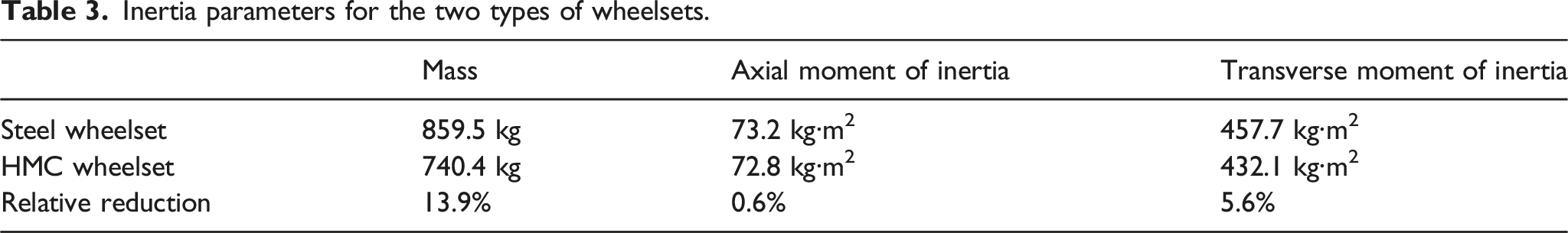
With very small idealisation, the railway wheelset can be considered as a solid of revolution. Therefore, the moment of inertia is equal for each transverse axis through the centre of gravity, which is used as the reference point. The relative reduction is obtained by dividing the difference between the parameters of the two wheelset types by the parameter of the steel wheelset, which is considered as the reference. For instance, the relative reduction of the mass is calculated in the following way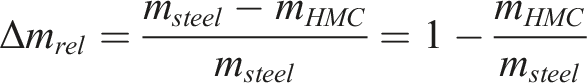
It can be seen that the use of the HMC axle notably reduces the wheelset’s mass by approximately 14%, but has relatively little effect on the moments of inertia, especially on the axial moment of inertia. The reason for this is that the moments of inertia are strongly influenced by the wheels, because their mass particles have a larger distance to the centre of gravity and thereby making a stronger contribution than those of the axle. Since for both wheelsets the same conventional steel wheels are used, the moments of inertia of the entire wheelset are only weakly affected.
In an investigation about the interaction between vehicle and track, also the dynamic behaviour of the track has to be taken into account, since a completely rigid track can lead to unrealistic results. A convenient way to model the dynamic behaviour of the track within the multibody model formalism is the use of a substitution model. In such a substitution model, the track is represented by an appropriate combination of ‘standard elements’, that is, rigid bodies, springs and dampers, with suitable parameters so that the model reproduces the track’s frequency response. Chaar and Berg
36
present several substitution models. Figure 8 shows the model developed by Chaar and Berg, which is used for the present investigation. Substitution track model by Chaar and Berg.
36
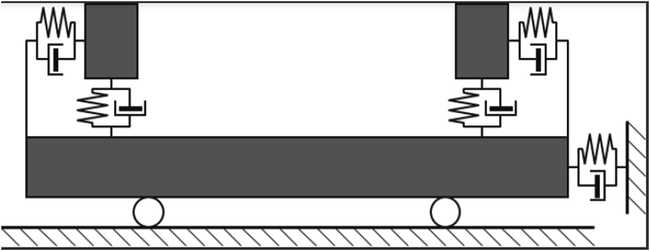
This track model was chosen, because it permits independent vertical and lateral motions of the rails, while in other substitution track models the rails and the sleepers are represented by one rigid body. This independent motion becomes important for curve negotiation, where the lateral forces occurring at the two wheels can strongly differ due to flange contact.
The track geometry data includes curvature, superelevation and the track irregularities, that is, the lateral and vertical deviations from the ideal rail position. The data, which describes 14 km of a section of a real metro line in Madrid, was provided by Metro de Madrid. In this section, the minimum curve radius is 192.3 m, and the maximum superelevation is 150 mm. The distribution of the curvature is shown later in Figure 12.
In the context of the running behaviour, the wheel-rail geometry is an important factor. The data, too, was provided by Metro de Madrid. For the rails, the profile UIC54 with an inclination of 1:20 is used. Since the new wheelset is adapted to the international standard gauge, a value of 1435 mm is set for the track gauge. The wheel profile is a bespoke profile used by Metro de Madrid. Up to a linearisation amplitude of 7 mm the equivalent conicity does not exceed 0.02,614, that is,
The multibody system representing the vehicle was built in the commercially available program SIMPACK.
37
Figure 9 shows a visualisation of this model. Multibody model of the investigated vehicle.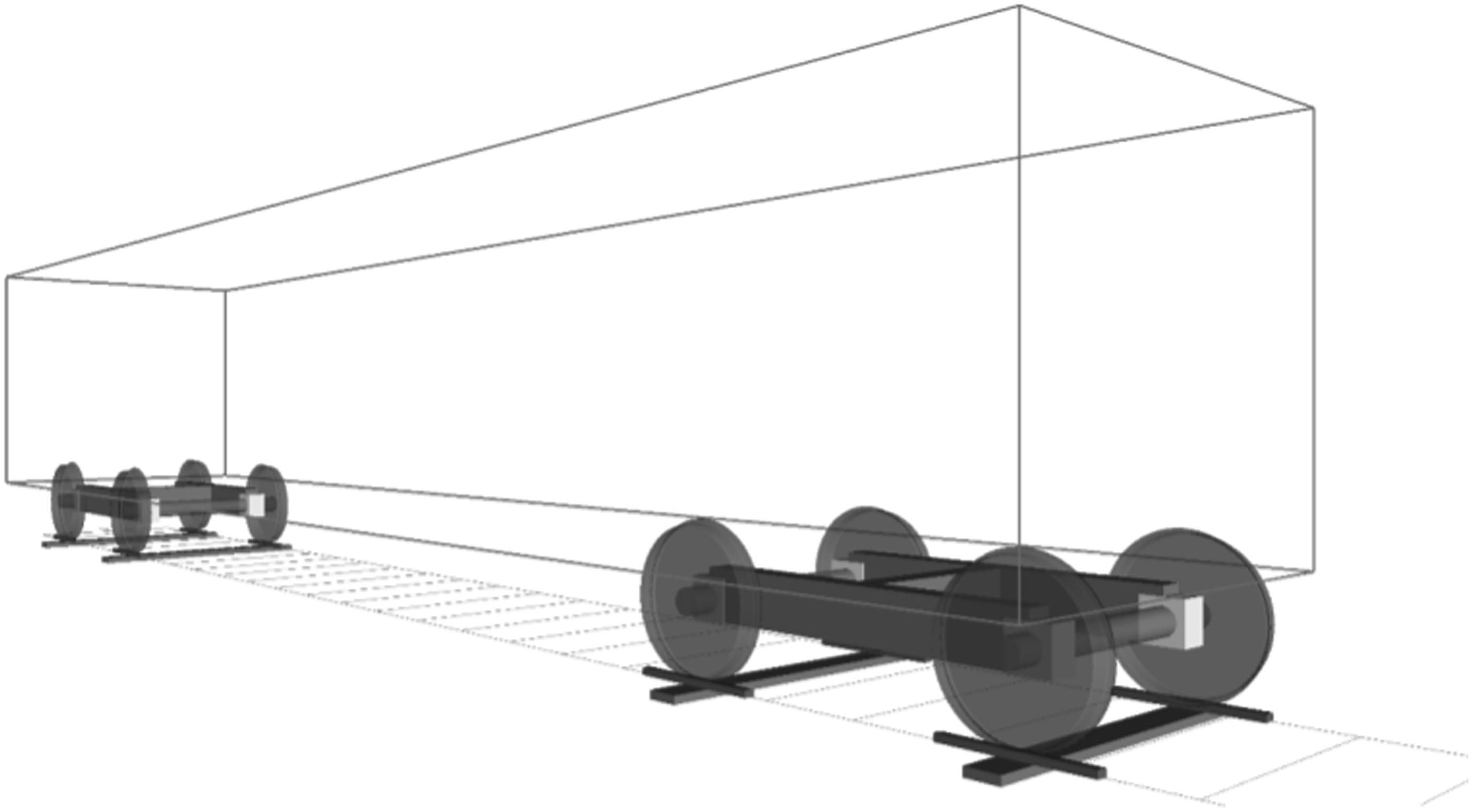
Results: Running on a curved metro line
In order to investigate the impact of the wheelset types on the dynamic behaviour, the running of the vehicle on a metro line based on real data is simulated using the multibody model described in the previous section. Here, two variants of the vehicle model, which use the corresponding sets of inertia parameters listed in Table 3, are used. For the scenario of running on the curved metro line, a constant running speed of 54 km/h is applied, because for this running speed the cant deficiency does not exceed 150 mm, which is a typical limit value. For the results presented in this section, a friction coefficient of
In order to evaluate the impact of the reduced wheelset inertia the following physical quantities are considered. • The dynamic vertical wheel-rail force, • The wear number, also known as the
These quantities are evaluated for the contacts of the leading wheelset (wheelset 11) and of the trailing wheelset (wheelset 12) of the vehicle’s leading bogie. Figure 10 shows the dynamic vertical forces, Dynamic vertical wheel-rail forces, 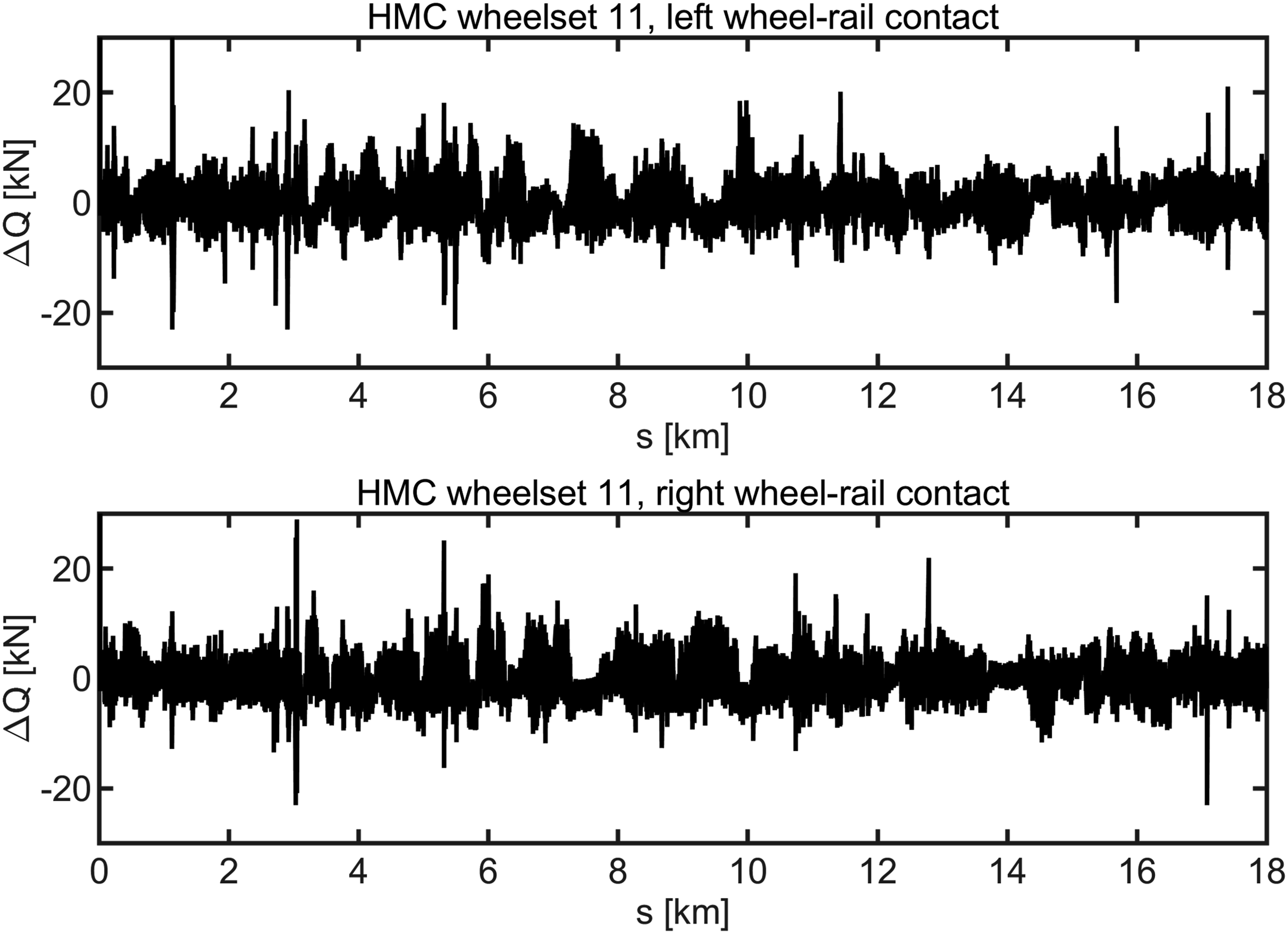
The comparison of the results obtained for the steel wheelset and for the HMC wheelset show that the dynamic vertical forces,
Standard deviations,
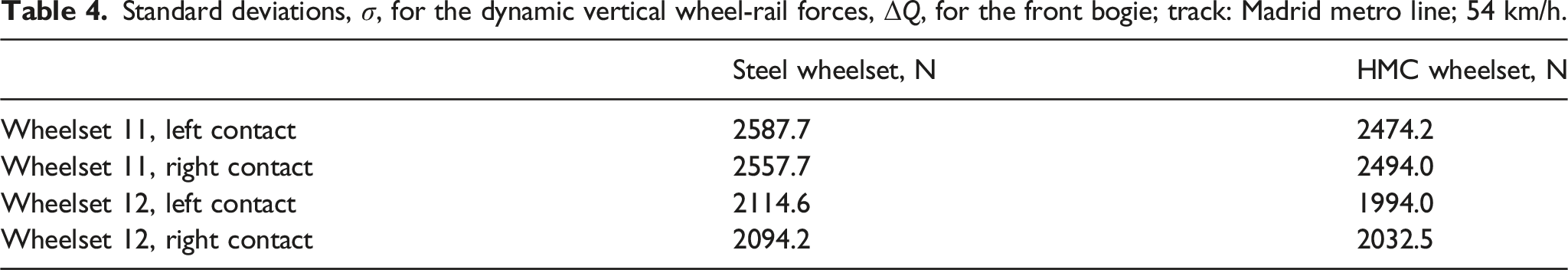
The standard deviations of the dynamic vertical wheel-rail force,
However, in these calculations a curved track including superelevations is used. These curves and superelevations already cause changes of the vertical forces,
According to Table 4, the highest standard deviation, Fourier spectra for the dynamic vertical wheel-rail forces, 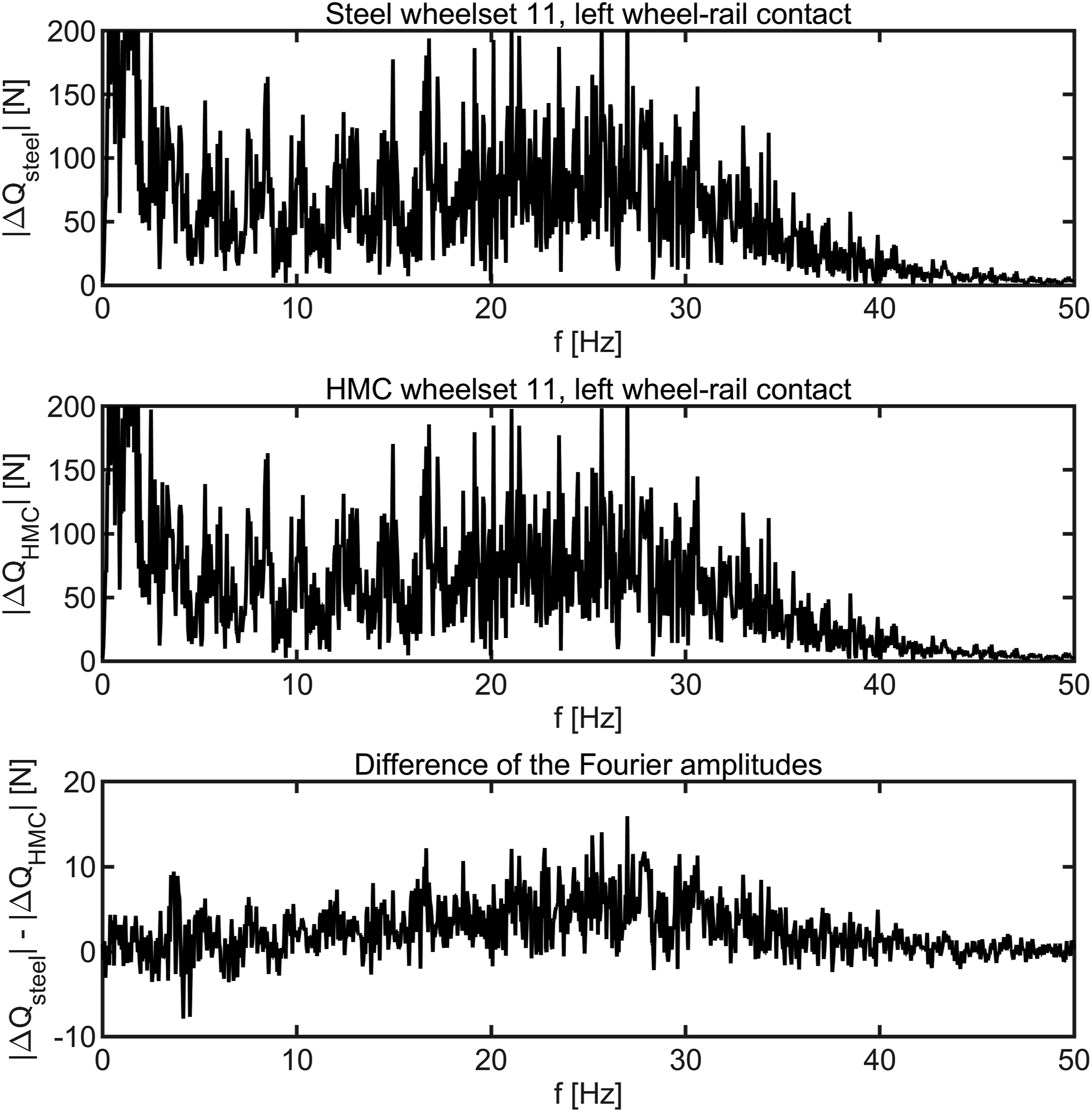
The comparison of the spectra shows that for the HMC wheelset, lower amplitudes occur in the range between 15 Hz and 35 Hz. Using a running speed of
In conclusion, the reduction of the dynamic vertical force due to the lower mass of the HMC wheelset is demonstrable, but this reduction is moderate. In this context, it has to be noted that the unsprung mass is not equal to the wheelset mass but includes also the axle boxes. In the present model, each axle box has a mass of
Next, the wear number
Figure 12 shows the total wear numbers at the four wheel-rail contacts of the leading bogie for the HMC wheelset. For a clearer illustration, the curvature of the line, that is, the reciprocal value Wear number 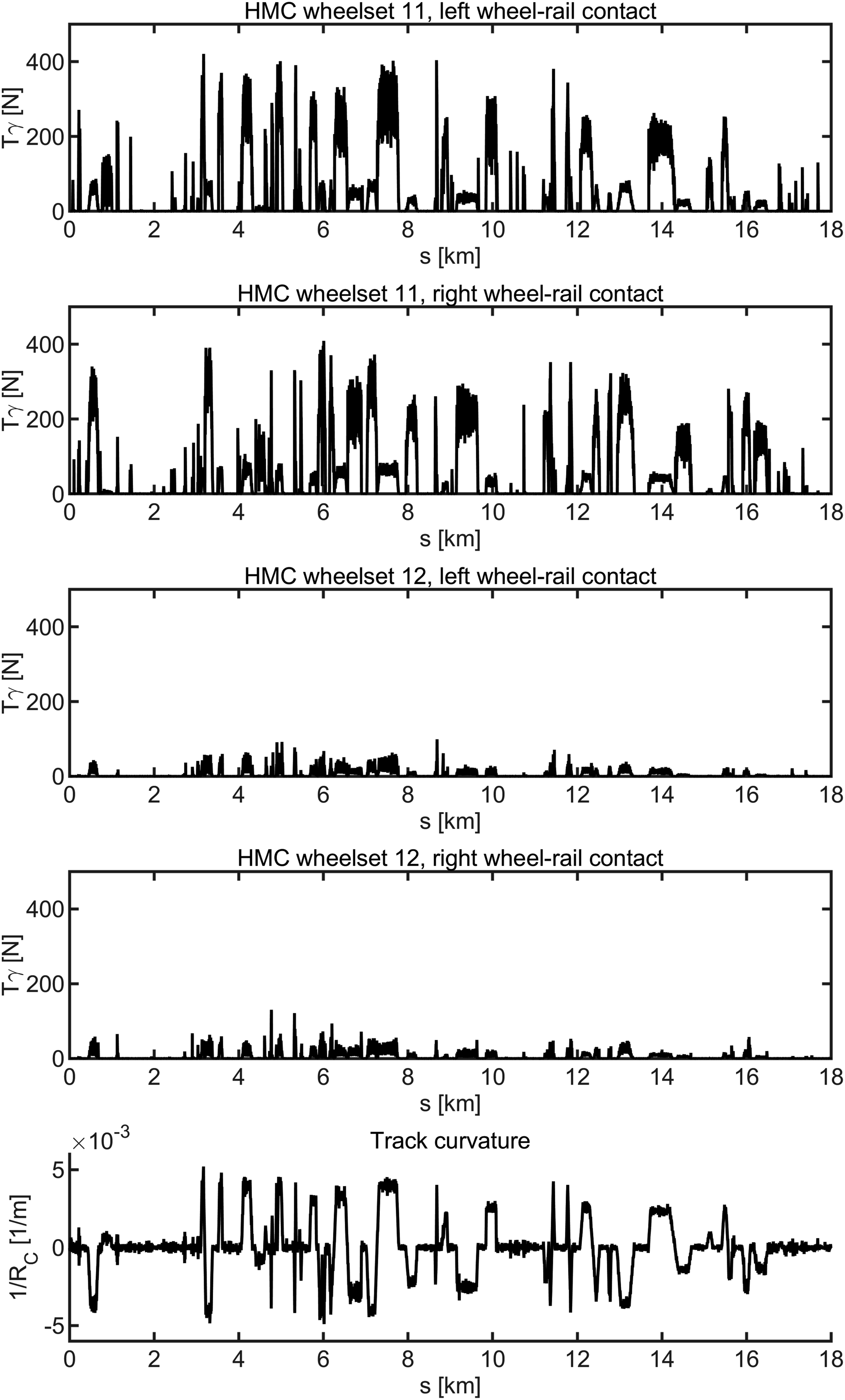
It can clearly be seen that the
Also here, the results obtained for both types of wheelsets are rather similar so that in a direct comparison of the curves for
There are two important effects, which cause damage in the wheel-rail contact, namely, rolling contact fatigue (RCF) and wear. According to Burstow,
38
the strength of these effects depends on the magnitude of the • • 15 N < • 65 N < •
This classification indicates that a reduction of the
Based on these ranges, an analysis of the relative importance of the different damage types was performed for the full track length used in the simulations, comparing the steel wheelset and the wheelset with HMC axle. In total, the comparison of the results reveals that the wheelset type has no apparent impact on the partition of the damages, that is, the share of different damage types is very similar for the two wheelsets considered. For the leading wheelset, it is found that in approximately 62% of the contact conditions obtained from the multibody simulation the
For the trailing wheelset, as shown in Figure 12, the
A useful indicator for the overall energy dissipated in the wheel-rail contact is obtain by integrating the wear number, 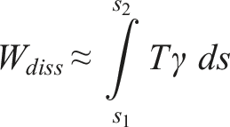
Integrals of the
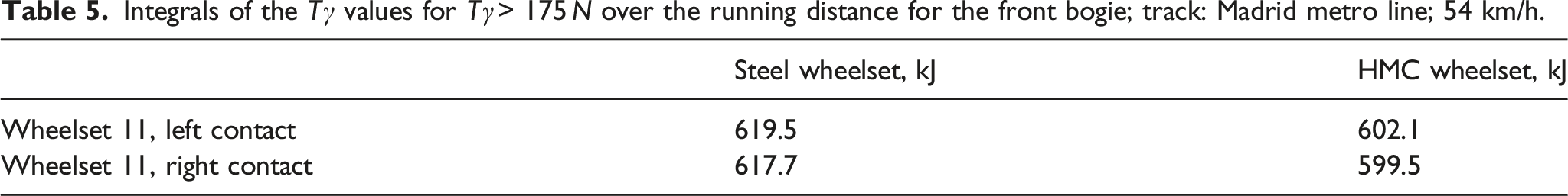
The comparison of the results shows that the values for the HMC wheelset are approximately 3% lower than those for the steel wheelset. Therefore, it can be expected that the lighter HMC wheelset enables a slight reduction of wheel-rail contact wear.
In total, the results obtained from the running dynamics analysis indicate that the lighter HMC wheelset in fact reduces the dynamic interaction between the vehicle and the track. This can contribute to the reduction of the maintenance effort of the vehicle as well as of the track and can thereby improve the overall economy of the entire system ‘railway’ including the rolling stock and the infrastructure.
Conclusions
In this paper, an overview of the work performed within the ‘wheelset of the future’ work package of the NEXTGEAR project is presented. The work details the three concepts for a lightweight HMC railway axle and leads to a preliminary design for the lightest mass concept. This comprised a full-length carbon fibre reinforced composite tube with an overwound central section for flexural stiffness and metallic collars bonded to either end. A principal requirement was lightweighting and the selected HMC concept resulted in a mass saving of over 63% compared to the conventional, hollow steel axle.
All in all, a 63% mass reduction of the axle corresponds to a 14% wheelset mass reduction and an 11% unsprung mass reduction. This leads to a 4% reduction of the standard deviation of the vertical dynamic forces. Furthermore, it leads to a cumulative reduction of wear numbers exceeding 175 N by about 3%. The benefits of an isolated intervention on the axle are, therefore, moderate. To obtain more significant benefits, perhaps the most suitable use for the technological innovation presented here would be in conjunction with other lightweighting technologies such as near-net shape axleboxes, lightweight axlebox bearings and a lightweight carbody, all of which are currently under investigation in EU research programmes.
Moreover, in this paper, the HMC concept design addressed not only the sizing and fibre layup of the composite parts, but also a solution for joining the metallic collars to the primary composite tube providing the interface of the axle to the wheels and bearings. The inboard end of the collar is subject to high bending loads requiring the collar to include a taper which was overwound to reduce peel stresses.
The research also entailed the analysis of the manufacturability of the HMC axle and an AFP method was presented. This solution afforded complete process automation and repeatability, albeit with measurable mass penalty.
Maintainability of the HMC axle using conventional ultrasonic testing methods showed potential. However, the adhesive bond and impedance mismatching with the collars led to the proposal of an in-situ structural health monitoring solution for continuous monitoring.
The effect of ballast impact on the surface of the axle was evaluated numerically. Penetration damage to a depth of 13.5 mm of the outer surface was predicted, mainly as matrix failure. Shielding solutions both integral and independent of the axle were proposed.
A dynamic simulation showing the effect of the mass reduction of the HMC railway axle on track loading and damage characteristics was presented. While the inertia of the wheelset remains dominated by the large diameter wheels, some advantages of the lightweight axle were evident.
Although the aim of the research was to assess the feasibility of the HMC axle up to a Technology Readiness Level (TRL) 3, the results obtained showed a clear potential for a significant reduction of the total unsprung masses which could not be achieved using conventional metallic materials. The benefits arising from the reduction of the unsprung masses are however traded for a more complex manufacturing process, hence, a higher initial cost, and more complex non-destructive inspection techniques. In this regard, the use of SHM to complement NDT inspection could be an effective way to ensure the highest safety levels and reduce maintenance costs.
The results produced from this collaborative project represent a useful starting point for future research addressing the further development of a HMC wheelset. It is envisaged that this work will stimulate a re-thinking of standards for railway axles, especially in view of using non-conventional materials and smart methods for structural health monitoring in the future.
Footnotes
Acknowledgements
The authors would like to acknowledge Metro de Madrid (Mr Juan Moreno) for providing information required to perform vehicle dynamics simulations.
Declaration of Conflicting Interests
The author(s) declared no potential conflicts of interest with respect to the research, authorship, and/or publication of this article.
Funding
The author(s) disclosed receipt of the following financial support for the research, authorship, and/or publication of this article: This work was conducted as part of work package 3 of the NEXTGEAR Project, S2R-OCIP1-02-2019 [Grant number: 881803], which is ascribed under the Shift2Rail Program funded by the EU Horizon 2020 Research and Innovation programme. The second author would also like to acknowledge the funding support of the Engineering and Physical Sciences Research Council through the: EPSRC Future Composites Manufacturing Research Hub [Grant number: EP/P006701/1] and EPSRC Industrial Doctorate Centre in Composites Manufacture [Grant number: EP/L015102/1].
Appendix 1
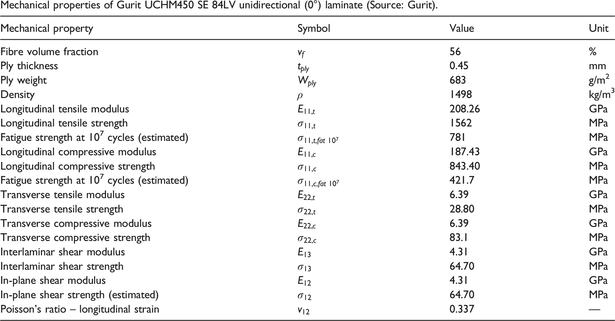
Table A1.
Mechanical properties of Gurit UCHM450 SE 84LV unidirectional (0°) laminate (Source: Gurit).
| Mechanical property | Symbol | Value | Unit |
|---|---|---|---|
| Fibre volume fraction | 56 | % | |
| Ply thickness | 0.45 | mm | |
| Ply weight | 683 | g/m2 | |
| Density | 1498 | kg/m3 | |
| Longitudinal tensile modulus | 208.26 | GPa | |
| Longitudinal tensile strength | 1562 | MPa | |
| Fatigue strength at 107 cycles (estimated) | 781 | MPa | |
| Longitudinal compressive modulus | 187.43 | GPa | |
| Longitudinal compressive strength | 843.40 | MPa | |
| Fatigue strength at 107 cycles (estimated) | 421.7 | MPa | |
| Transverse tensile modulus | 6.39 | GPa | |
| Transverse tensile strength | 28.80 | MPa | |
| Transverse compressive modulus | 6.39 | GPa | |
| Transverse compressive strength | 83.1 | MPa | |
| Interlaminar shear modulus | 4.31 | GPa | |
| Interlaminar shear strength | 64.70 | MPa | |
| In-plane shear modulus | 4.31 | GPa | |
| In-plane shear strength (estimated) | 64.70 | MPa | |
| Poisson’s ratio – longitudinal strain | 0.337 | — |