
Abstract
The potential for lightweighting of railway axles was investigated to primarily reduce the unsprung mass of rail vehicles. The reduction of unsprung mass equates to an overall lighter train, which will help to reduce track damage, energy consumption and total operating costs. Two approaches were considered for the lightweighting of railway axles, which include a hollow axle design and material substitution using advanced composite materials, to offer a more track-friendly design. The first approach showed that if the outer diameter of a hollow axle is increased by 30% over that of the solid axle diameter, a mass reduction of 56% is achievable for a hollow steel axle design. The second approach explored further mass savings that could be achieved through material substitution of a hollow axle. A systematic approach to material selection for the design requirements and constraints of a railway axle was considered to identify the candidate materials for the application. The optimum material identified was a ‘bismaleimide matrix + carbon fibre composite.’ A hollow axle manufactured from this composite material offered 64% savings in mass when compared to a hollow steel axle, and 84% savings in mass when compared to a solid steel axle. Estimates for the cost savings of lightweighting of an axle were quantified by utilising Network Rail’s variable usage charge calculator, to assess the track access charge savings that can be achieved. For the scenario described in this paper, a potential £5.58 million per year could be saved for an intercity 220/M Voyager train, in terms of variable usage charges, over the entire fleet of 34 trains (four carriages per train) by implementing hollow composite axles. This is an example of a costing approach to support the decision making of lightweighting of rail vehicles.
Keywords
Introduction
Today’s performance requirements for the global rail industry demand that trains are more reliable, efficient and accommodate an increased capacity for more passengers. Reports from 2007 show trends in increasing weight of UK rail transportation vehicles over the last 30 years. 1 This is primarily due to improvements in passenger environments on board trains (for example, heating, ventilation and air conditioning systems, crashworthiness and improved accessibility) coupled with a metallic construction. 2
These heavier rail vehicles put a strain on the network and result in
3
:
Increased damage to the track, thereby resulting in higher costs for infrastructure, maintenance and renewal. Increased energy to operate, making them more costly to run as well as increasing the probability of higher CO2 emissions in the energy production lifecycle. Not to mention the necessity for higher rated traction and braking systems to facilitate the duty cycles of trains.
The UK’s Rail Technical Strategy 2012 4 echoes the European Rail Sector Sustainable Mobility Strategy 2010, 5 which highlights the need for lighter and more efficient trains to deliver improved rail capacity and performance. In particular, it identifies lightweight materials as a key enabler in reducing energy consumption.
Steel has long been used as a structural material for rolling stock vehicles. Its good strength, formability and weldability properties coupled with its relatively low cost make it a versatile material option. However, the desire to achieve a lightweight design and reduce production costs are the two main driving forces behind the introduction of new materials in railway applications. 6 Fibre-reinforced polymer (FRP) composites are one such material system that meets these aims. These materials feature a polymer matrix with reinforcing fibres, and are favoured for their high strength-to-weight ratio, corrosion resistance and fatigue resistance properties.
In comparison to the aerospace, automotive and marine industries, the railway industry has been perceived as slow to integrate lightweight materials (primarily FRP composites) into their structures. The main barrier to their widespread adoption has been material cost. However, composite design can reduce manufacturing costs (in terms of a life-cycle costing perspective) by reducing the number of parts, assembly steps and assembly time. 7
As part of the modular urban guided rail systems (MODURBAN) European rail project, the mass breakdown of a typical six-car-set metro vehicle was quantified. It concluded that the bogies are the largest mass contributor for a typical passenger rail vehicle, accounting for 41% of the total tare mass. 8 They are thus a prime candidate for lightweighting in rail vehicles.
The bogies are the chassis that contain the wheelsets and support the rail vehicle body. Each wheelset is formed of two wheels connected by an axle (see Figure 1), which comprises the unsprung mass. This is the mass that rests directly on the rails and does most damage to the track.
Railway wheelset comprising an axle and press-fitted wheels.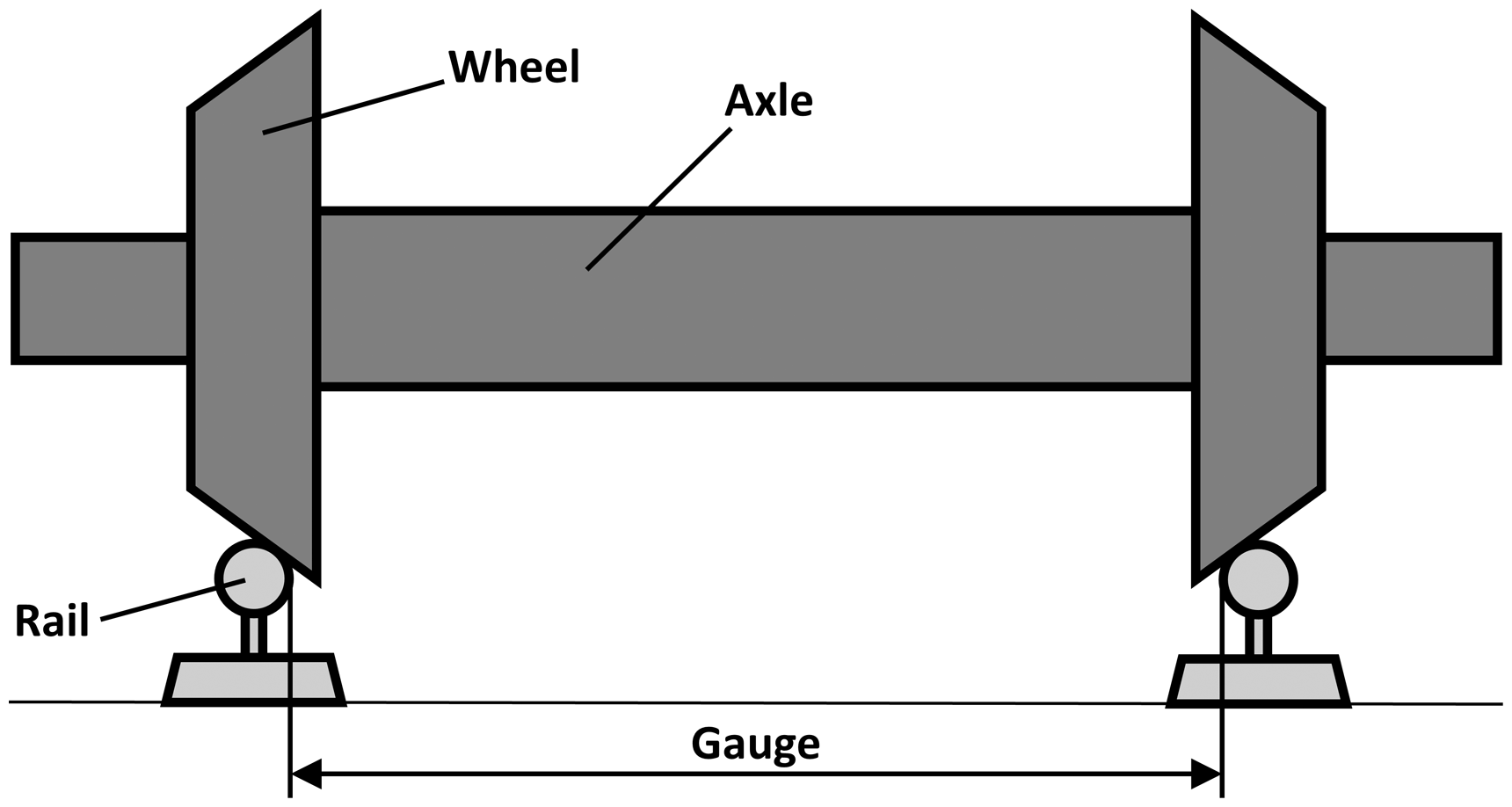
There have been a few notable projects to lightweight the bogie through a composite construction, mainly focussing on the bogie frame. These are summarised in chronological order as follows:
Lightweight carbon fibre rail bogie frame developed by University of Huddersfield in conjunction with ELG Carbon Fibre Ltd, Alstom Transport and Magma Structures – 2018. Kawasaki efWING bogie with carbon fibre-reinforced plastic leaf springs – 2015. Research into carbon fibre-reinforced polymer (CFRP) composite bogie frames by The Japanese Railway Technical Research Institute – 2008. German intercity coach with FRP bogie frames (developed by Messerschmitt-Bolkow-Blohm (MBB) and AEG Westinghouse Transport-Systeme) – 1988.
In terms of lightweighting of rail wheelsets, there has only been one published project, led by British Rail in the UK, addressing lightweighting of a rail axle. British Rail investigated the use of CFRP composites for rail vehicle axle tubes, during the development of the advanced passenger train (APT). 9
This paper aims to highlight the potential for lightweighting of railway axles. A typical rail axle constitutes one-third of the mass of a conventional wheelset. The benefits of a hollow axle design and material substitution using FRP composite materials for the axle will be investigated. Ultimately, the reduction of unsprung mass correlates to an overall lighter train, which will reduce track and infrastructure damage, reduce energy consumption, reduce total operating costs and possibly offer faster journey times.
Railway axles
A railway axle is a single rigid beam and is one of the most design safety critical components of a bogie, in which the design driver is fatigue strength. The axle serves to transmit the driving torque to the wheels, maintain the position of the wheels relative to each other and supports the vehicle body. Railway axles used on European rail networks are typically manufactured from vacuum-degassed steel grade EA1N,10 via open die forging or a rolling process. The surfaces are then post machined to achieve a concentric and balanced axle. Historically, axles used to be solid in terms of their cross section, whereas increasingly, hollow axles are being used for lightweighting of rail vehicles. Furthermore, an axle is designed by inertial loading and is therefore considered a prime candidate for a composite solution.
There are two main design strategies for lightweighting of railway axles as detailed below:
Alter the geometry of the axle by boring the middle of a solid axle to form a hollow axle, or by reducing the axle length. The length of the axle is constrained by the track gauge length, and there is limited potential to reduce the axle length with respect to accommodating the axle box and other ancillary components onto the axle to offer mass savings. Alternative lightweight materials can be explored to offer further potential mass savings for a hollow axle.
These design strategies will be explored in this paper and the potential cost savings for such a design will be demonstrated through considerations of track access charges.
Benefits of a hollow axle
The maximum bending stress occurs on the outer surface of the axle, whereas the least stressed part of an axle occurs in the centre region. The removal of this material by hollowing out the axle can have a substantial effect on the strength–mass ratio of the axle. 11 It is therefore the purpose of this section to consider the mass reduction benefits of a solid axle, compared to that of a hollow axle.
The analysis presented in this section compares the mass reduction as a function of the diameter ratio of a hollow axle to a solid axle, for constant maximum bending stress. In addition to the diameter notations specified in Figure 2, the following notations for mass, m, and bending stress, σ, are also used which relates to the solid and hollow axles using subscripts, s, and h, respectively.
Comparison of (a) solid and (b) hollow axle cross-section. Where, Ds, refers to the diameter of a solid axle, Do and Di, refers to the outer and inner diameters of a hollow axle respectively.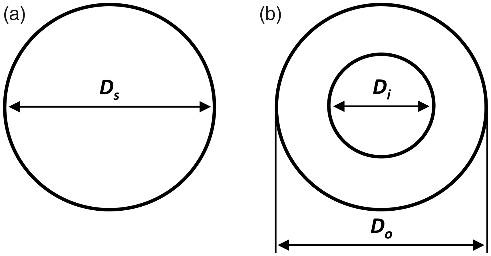
An expression for the maximum bending stress of a solid and hollow axle can be defined from Euler–Bernoulli beam theory. 12
Solid axle:
Hollow axle:
Thus, an expression for equal axle bending stresses can be formulated by equating the two proportions.

Defining the diameter ratio, R = Do/Ds, and substituting it into equation (1) yields an expression relating the inner and outer diameters of a hollow axle.

An expression for the mass of a solid, Ms, and hollow axle, Mh, can be defined by volume considerations, and since the material is unchanged, the density remains constant.
Solid axle:
Hollow axle:
Therefore, an expression for the ratio of masses can be shown by equating the two proportions.

Finally, an expression for the mass ratio as a function of the diameter ratio, R, can be achieved by substituting equation (2) into equation (3).

The mass ratio of a hollow to solid axle derived in equation (4) is represented graphically in Figure 3 for equal maximum bending stress. This shows that if the outer diameter of the hollow axle is increased by 10% over that of the solid axle diameter (R = 10%), then there is a 40% reduction in the mass of a hollow axle. The inner diameter of the hollow axle will increase correspondingly to maintain the equal maximum bending stress constraint, and thus the thickness of the axle wall will be reduced.
Reduction of the axle mass plotted as a function of an increasing diameter ratio for a hollow axle of equal maximum bending stress to that in a solid axle.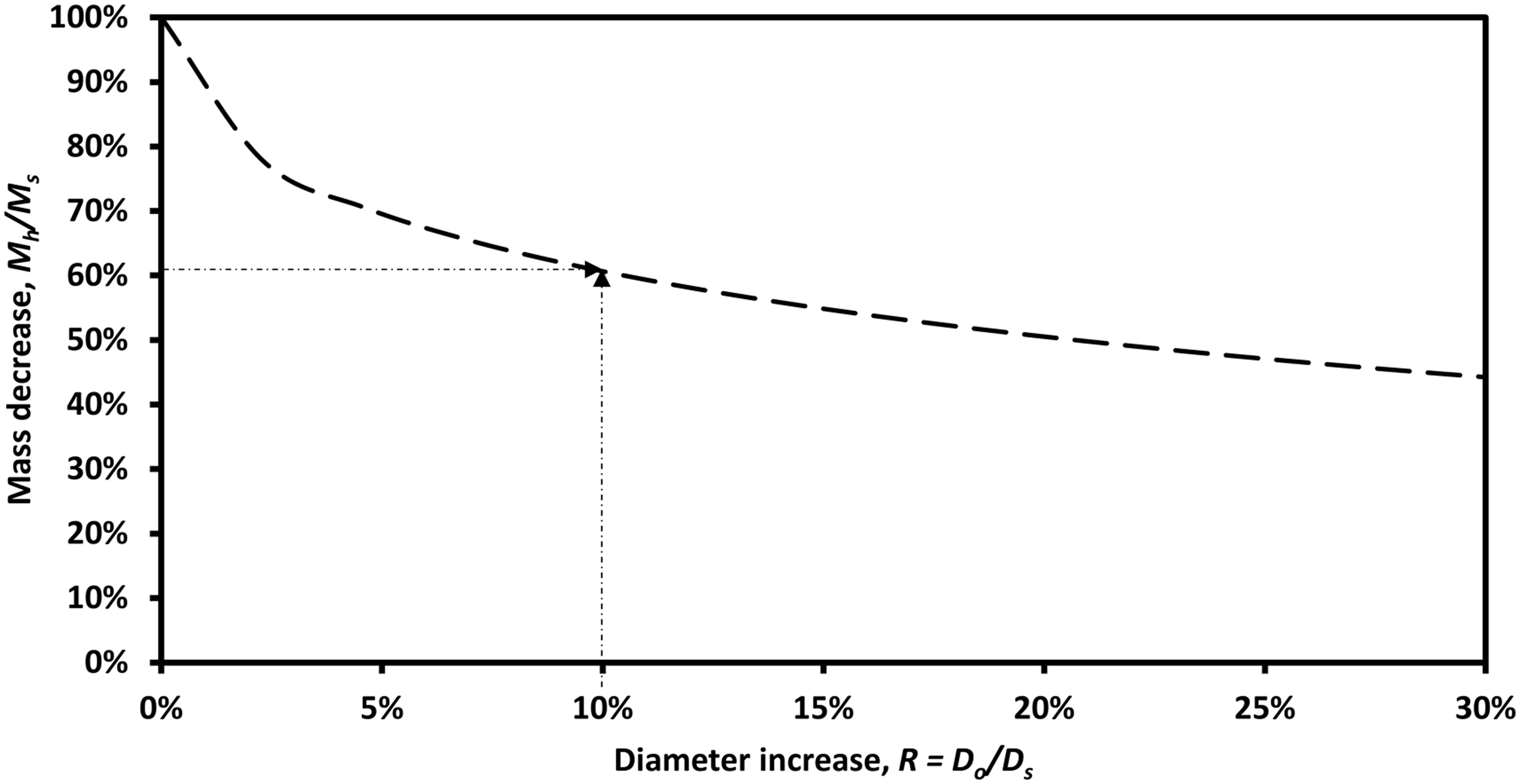
A diameter ratio, R, of 30%, was chosen as a suitable realistic upper limit as shown in Figure 3, given the space constraints of the wheelset. This represents that if the outer diameter of the hollow axle is increased by 30% over that of the solid axle diameter, a mass saving of 56% is achievable for the hollow axle. This design change yields a significant increase in the strength–mass ratio of the axle. However, any increase in the overall diameter of the axle will result in the redesign of the axle press fitted components, such as the wheels and axle boxes in the wheelset assembly process. In addition, there will be a cost associated with this redesign process. Despite this, it is envisaged that the mass savings correlating to reduced energy consumption will outweigh this from a life cycle costing perspective.
Material selection for lightweighting of axles
This section explores the potential for further reduction of axle mass through material substitution. Alternative lightweight materials are to be explored whilst meeting all known essential requirements and constraints for the application of a railway axle. The Cambridge engineering selector (CES) EduPack software of Granta Design Limited
13
was employed for two main reasons:
It has a large database of possible material options. It allows the user to specify material constraints in order to filter material choices based on only those materials that fulfil the necessary requirements specified.
The CES approach to material selection is well described by Ashby
12
and illustrated by Ashby and Cebon.
14
The approach can be summarised in the following five steps:
Problem definition Definition of the objective function Definition of the constraints Implementation of the material selection using material selection charts Interpretation of the results
This approach is not directly relevant to the application of railway axles since the functions, constraints and geometry are not well defined. Therefore, for the purpose of this study the axle will be modelled as a uniform, thick-walled, cross-sectional beam to simplify the material selection process.
At present, railway axles are most commonly made of EA1N grade railway steel, which is a high-carbon steel. The following analysis addresses the question if there is an alternative material that would provide a lighter solution at similar performance levels, using the CES software in accordance with Ashby’s material selection approach described above.8,12
Step one – problem definition
Material selection criteria for a railway axle in accordance with the CES approach.
Step two – definition of the objective function
As stated previously, the objective of the material selection exercise is to reduce the mass of the hollow axle. Therefore, the objective function is expressed in terms of the mass of a uniform, thick-walled, cross-sectional axle.

Step three – definition of the constraints
In accordance with the CES approach, the constraints of the axle design need to be defined in terms of ‘performance indices’ and ‘attribute limits.’ Firstly, the performance index can be defined by considering the deflection of the axle under static loading conditions. This is modelled as a beam in four-point bending as shown in Figure 4.
Outboard bearing configuration of a non-powered, hollow axle, rail wheelset under static loading conditions, modelled as a beam in four-point bending.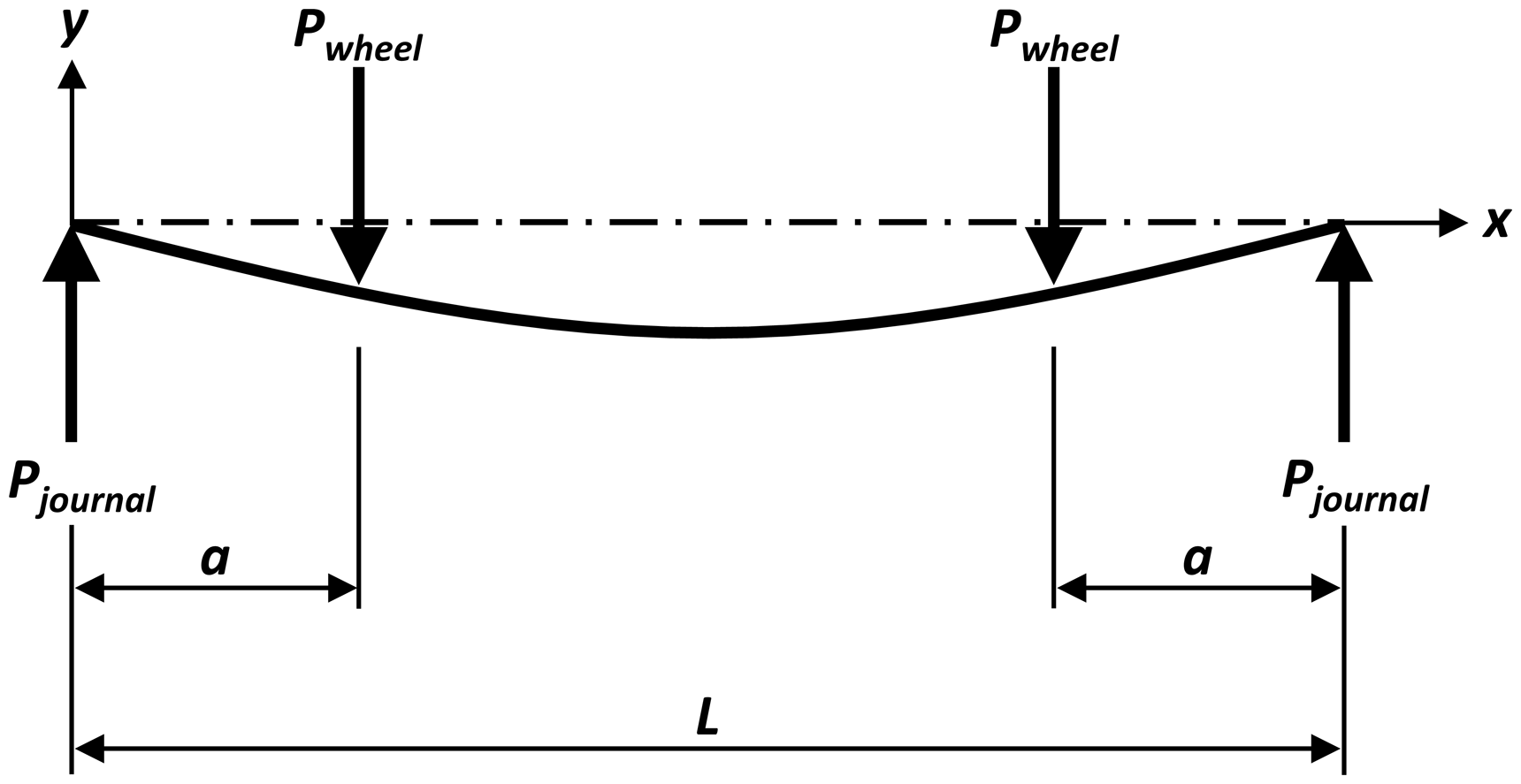
The maximum deflection of a beam in four-point bending occurs at the centre span.
12

The stiffness, S, of a beam in four-point bending can be expressed as,

The second moment of area, I, for a thick-walled hollow circular beam is as follows.
12

Variables, L, a and Do, are constraints that are fixed. The beam stiffness, S, is undefined and varies depending on axle load for each train. An expression in terms of axle mass including beam stiffness can be determined by substitution of equations (6b) and (7) into equation (5).

Hence, the mass, m, of the axle is minimised by selecting materials with a smaller ratio of density to Young’s modulus. The CES approach presents the reciprocal of this ratio as the stiffness performance index, M1. In this form, the objective is to maximise the performance index when selecting materials to minimise the axle mass, as shown in equation (9).

Alternative material choices are identified after applying the constraints to the selection process, and these are inputted as ‘attribute limits’ in the CES software. Since the material, EA1N grade railway steel, is not present in the CES database, the materials are compared to ‘Carbon steel, AISI 1030, normalised’ as a benchmark, which is a close approximation to the current steel composition. The attribute limits are specified:
Over a typical 30-year lifetime of a passenger rail vehicle, it is envisaged that the railway axle will experience fatigue cycles into the gigacycle regime (109 cycles). However, the endurance limit attribute in the CES software is defined as the maximum applied cyclic stress amplitude for a fatigue life of 107 cycles. Therefore, a suitable minimum endurance limit of 250 MPa is specified to account for the knockdown in fatigue strength. For reference, the fatigue strength of the benchmark carbon steel has an endurance limit of 170–310 MPa, based on the CES software database. However, life cycle bending fatigue testing would need to be conducted to verify the fatigue strength of the materials. For the fire performance constraint, only materials with non-flammable ratings in the CES database will be considered. Further tests need to be carried out to assess the conformance of the materials to the fire, smoke and toxicity (FST) requirements specified in the British European norm BS EN 45545-2, detailed under requirement 7, for bogie structure and parts.
15
An additional constraint on fracture toughness, KIC, is specified (>20 MPa m1/2). This is to screen out very brittle materials that clearly are going to be unsuitable for the impact prone application.
For this analysis, cost is not considered as an attribute limit. This is to ensure that all potential materials that could be suitable for this application are presented and can be assessed in terms of their merits.
Step four – material selection
A material selection chart was constructed using the CES software, by plotting Young’s modulus against density on logarithmic axes, as shown in Figure 5. Each of the ‘bubbles’ on the chart represents a particular material and some of these have been labelled. Attribute limits have been imposed to filter out unsuitable materials and identify potential candidate materials that pass the requirements of all the constraints collectively (i.e. stiffness, fatigue, fire and fracture toughness combined). The objective is to determine a material with a high Young’s modulus and a low density in order to maximise the performance index, M1, shown in Figure 5 as a straight diagonal line of gradient 1. This line has been positioned to pass through ‘Carbon steel, AISI 1030, normalised’ (EA1N grade railway steel equivalent) used as a benchmark material. All the materials that lie on the line perform equally well as a light, stiff axle. Those above the line perform better and are of particular interest as candidate lightweighting materials.
Combined CES material selection chart for the axle stiffness constraint showing only those materials that pass the collective requirements of the: stiffness, fatigue, fire performance and fracture toughness constraints. Each of the ‘bubbles’ represents a particular material.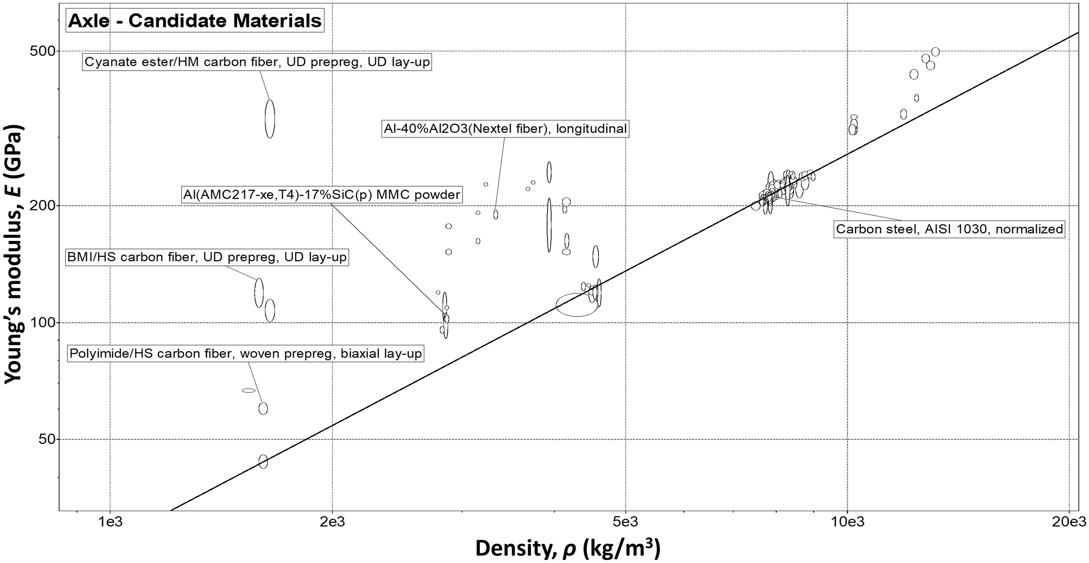
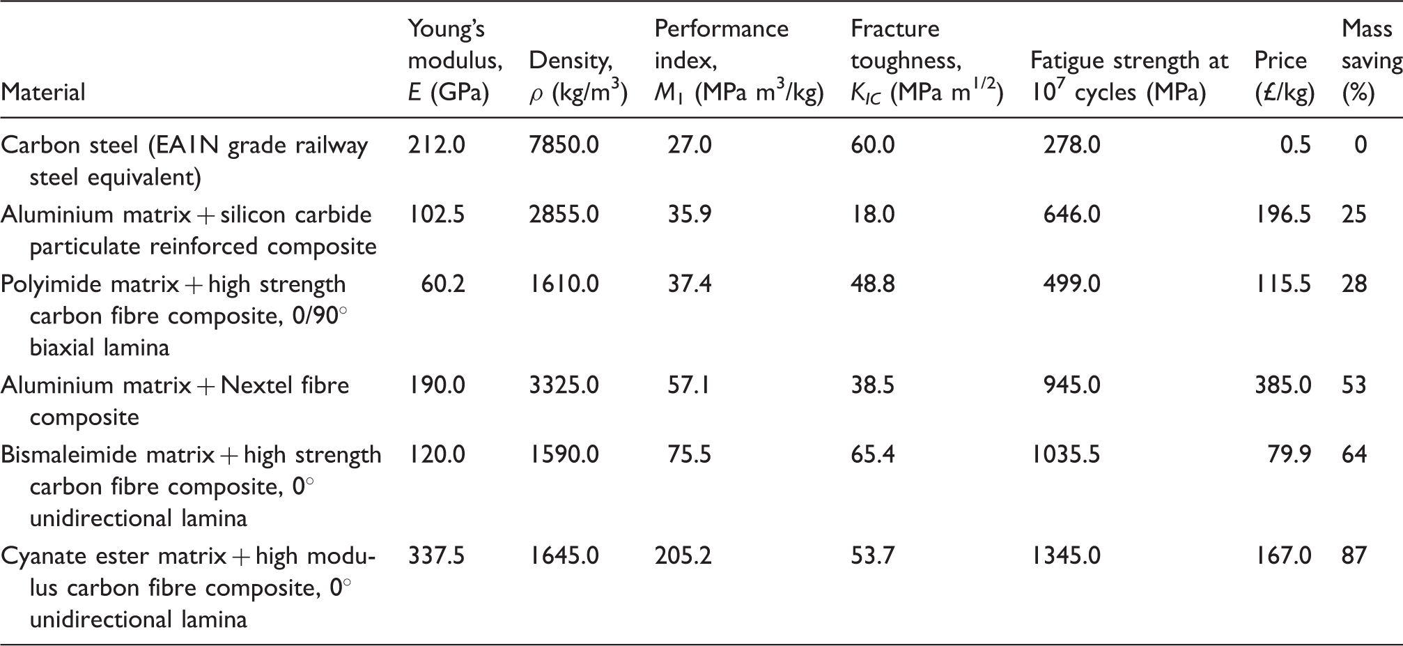
A selection of axle candidate materials that pass the combined requirements of the: stiffness, fatigue, fire performance and fracture toughness constraints.
Step five – interpretation of results
The final step in the CES material selection approach is to assess the viability of the proposed solutions. Interestingly, the five shortlisted candidates are all advanced composite materials. The three best options (i.e. those with the highest values of M1) include one metal–matrix composite and two FRP composite materials. These are the: ‘aluminium matrix + Nextel fibre composite,’ ‘bismaleimide matrix + carbon fibre composite’ and the ‘cyanate ester matrix + carbon fibre composite.’ The results indicate that hollow axles manufactured from these materials would be 53%, 64% and 87% lighter by mass, respectively, than a hollow steel axle. This is a significant mass reduction and is due to the inherent high strength-to-weight ratio of composite materials.
The ‘aluminium matrix + Nextel fibre composite’ is currently used in aerospace technology. It is the most expensive material option out of the five selected, and is 770 times more expensive per kilogram than the current carbon steel. Its fracture toughness is also lower than the steel, making it more brittle and potentially unsuitable for the application of an axle, which is prone to ballast impact. Overall, the cost premium does not justify the mass savings for this material.
The ‘cyanate ester matrix + carbon fibre composite’ provides the greatest mass savings out of all the material options, at 87% mass savings compared to the carbon steel. It is currently used for applications including high-performance spacecraft, aircraft, missiles, radomes and antennas. Its fracture toughness as with the aluminium matrix composite is below that of carbon steel, and hence poses issues with regard to ballast impact. In terms of cost per kilogram, the cyanate ester matrix composite is 334 times more expensive than the carbon steel.
The ‘bismaleimide matrix + carbon fibre composite’ is currently used in aerospace components where elevated temperature performance is required, including high-speed flight controls, engine inlets and missile components. It is less expensive per kilogram than the aluminium matrix composite; however, it is still 160 times more expensive than the carbon steel. Moreover, it offers 64% mass savings compared to the carbon steel at less of a cost premium. This material is a good choice in terms of a trade-off between possible mass savings and cost, whilst providing good fracture toughness and fatigue strength.
Despite the attractive mass savings that these advanced composite materials offer, the high material cost premium tends to limit their use to high-performance aerospace components. However, it can be argued that for the application of mass production composite railway axles, this high upfront material cost is outweighed when considered from a life costing perspective to include reduced track and infrastructure damage, reduced energy consumption and reduced total operating costs.
From observation of Figure 5, a number of more conventional materials that lie closer to the performance index line would provide viable alternatives to carbon steel, although these options come with a trade-off in terms of reduced mass savings. A number of aluminium alloys and steels might provide similar performance levels at reduced cost.
There are various technical challenges that would need to be overcome to be able to design and implement an axle manufactured from advanced composite materials. The main challenges include conforming to the stringent FST requirements specified for the rail industry, satisfying the high-cycle fatigue strength requirements and issues of ballast impact. In addition to this, the high cost of advanced composite materials discourages the uptake into rail vehicle design, which has a relatively low annual volume production, in comparison with automotive and aerospace industries. It is envisaged that the rising emphasis on environmental policy concerned with energy consumption will motivate the lightweighting agenda in the rail industry, and as demonstrated, advanced composite materials cannot be ignored in this endeavour.
Track access charges
Network Rail are responsible for operating, refurbishing and maintaining Britain’s railway network. Rail operators pay various track access charges to Network Rail. This includes variable usage charges (VUCs), which Network Rail use to recover the track, civil and signalling wear and tear costs, that trains impose on the network. The VUCs are calculated on a pence per vehicle mile (p/vm) basis, and are levied on a national average basis. Therefore, the rate applicable to an individual vehicle is the same irrespective of where on the network that vehicle operates. 16
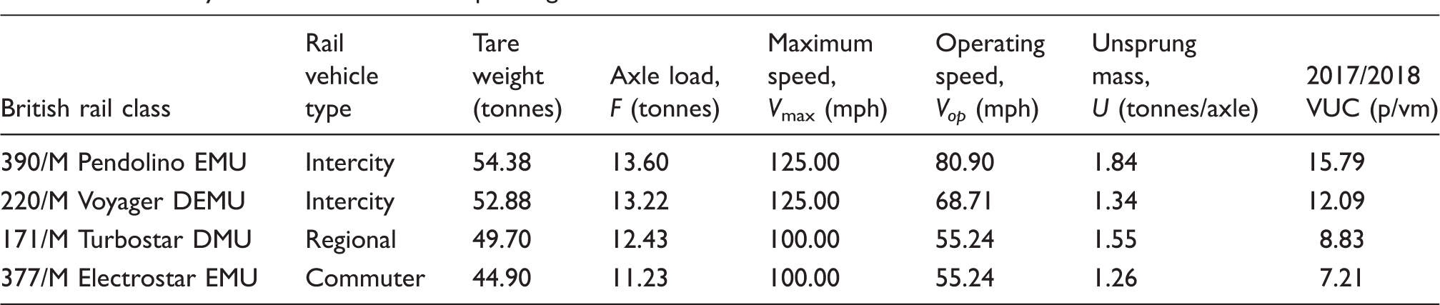
Summary of selected British rail passenger vehicle classes and attributes. 17
For the HS axle, a diameter increase ratio, R, of 30% will be assumed from the section ‘Benefits of a hollow axle’ corresponding to a reduction in axle mass of 56%, as compared to that of an SS axle. For the HC axle, the ‘bismaleimide matrix + carbon fibre composite’ material will be used, as identified in the material selection stage. The HC axle is reduced by 64% in mass compared to the HS axle as seen in Table 2, and is 84% lighter than an SS axle.
Figure 6 compares the unsprung mass per axle for each of the rail vehicle classes based on the three different axle configurations. For the purposes of this analysis, it is assumed that the SS axle contributes to 35% of the mass of one rail wheelset.
Unsprung mass per axle for four British rail vehicle classes: 390/M, 220/M, 377/M and 171/M, that have the following axle configurations: solid steel (SS), hollow steel (HS) and hollow composite (HC).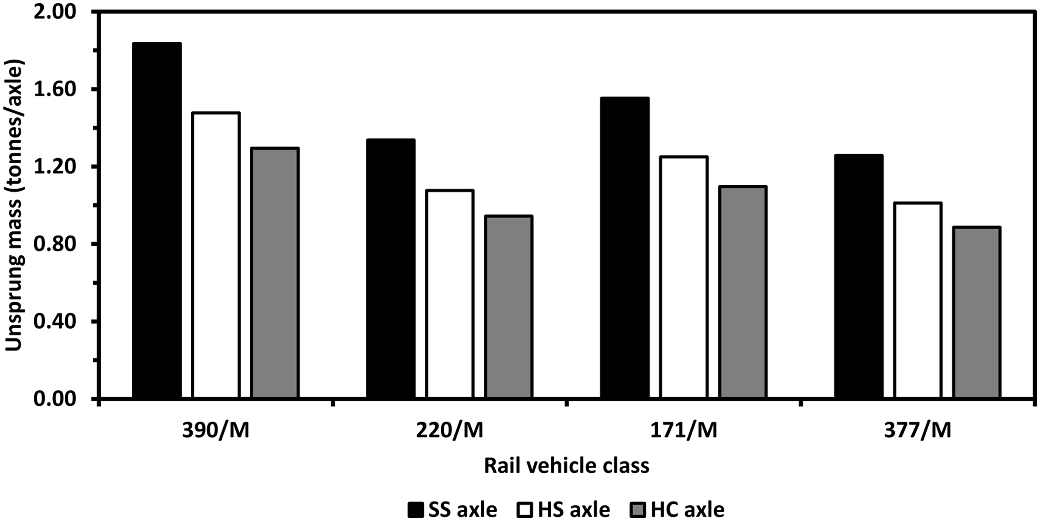
The overall reduction in the unsprung mass as a result of implementing a HS and HC can be observed in Figure 6. There is a 20% reduction in the unsprung mass for an HS axle, and a 29% reduction for a HC axle, both as compared to a conventional SS axle. To put this into context, the VUCs associated with each of the configurations above were calculated and normalised against the standard SS axle configuration. This is represented in Figure 7, showing the percentage VUC savings.
VUC savings for a hollow steel (HS) axle design and hollow composite (HC) axle design normalised against a solid steel (SS) axle design, for four British rail vehicle classes: 390/M, 220/M, 377/M and 171/M.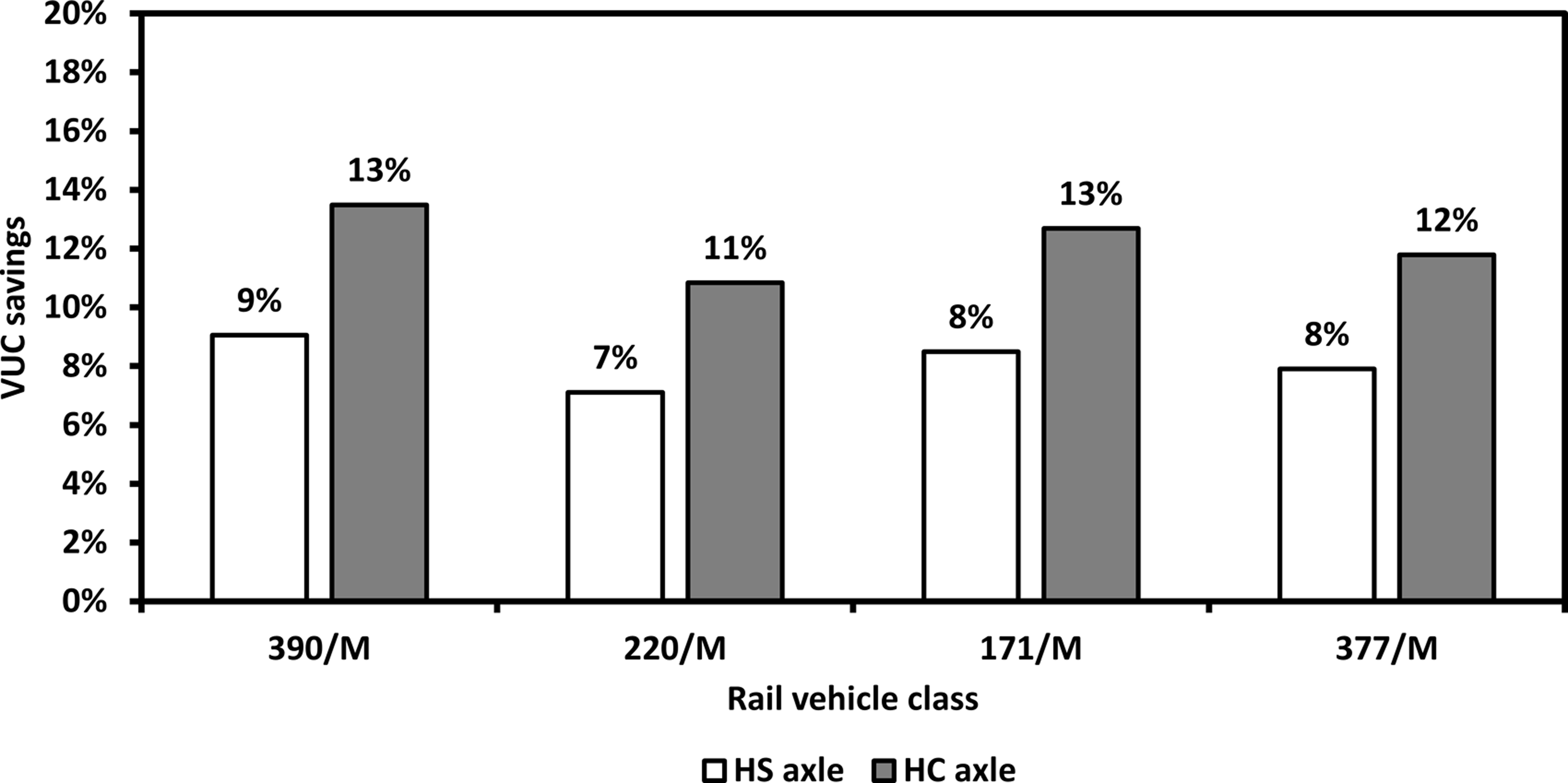
A HC axle provides the optimal design solution for lightweighting of an axle. A similar percentage saving in terms of VUC is seen for all four British rail vehicle classes, varying from 11% to 13%. The British rail motor vehicle class 390, Pendelino intercity train, and 171, Turbostar regional train, both offer 13% VUC savings. However, due to the combination of high unsprung mass and high speed of a Pendelino the damage caused to the tracks is amplified. 18 Therefore, lightweighting of the axle for this type of heavy, high-speed rail vehicle tends to significantly reduce the VUCs to rail operators, and hence results in a more track-friendly design.
A calculation is presented to demonstrate the VUC savings per year, for the British rail motor vehicle class 220, Voyager DEMU, with HC axles per wheelset as shown in Figure 8. This rail vehicle class was considered for this analysis since it demonstrated the lowest VUC savings per vehicle. This calculation is based on the following assumptions:
There is currently a fleet of 34 British rail vehicle class, 220/M Voyager DEMU trains operated by the Arriva Cross-Country service, each consisting of four carriages per train.
19
The average mileage data for 2016/2017 period are used for a 220/M Super Voyager DEMU train. In 2016/2017, the total mileage for the entire fleet of 220/M trains was 36,205,792 miles.
20
This equates to 1,064,876.24 miles travelled per (four carriages) train in a year (36,205,792 miles/34 trains).
From Figure 8, it can be seen that a significant sum of £5.58 million can be saved per year for a 220/M rail vehicle in terms of VUCs, over the entire fleet of 34 trains (four carriages per train) by implementing HC axles. A similar cost summation can be carried out for the other British rail vehicle classes to show profound VUC savings for the implementation of HC axles. Moreover, the economic benefit of lightweighting of the axle goes far beyond reducing the track access charges. Energy consumption, maintenance costs and operating costs will all tend to decrease for a lighter axle design and hence reduce the unsprung mass of the train, resulting in a more track-friendly train.
Graphical representation of 2017/2018 variable usage charge (VUC) savings per year, for a British rail vehicle class 220/M Super Voyager DEMU, with hollow composite (HC) axles, as opposed to the conventional solid steel (SS) axle configuration.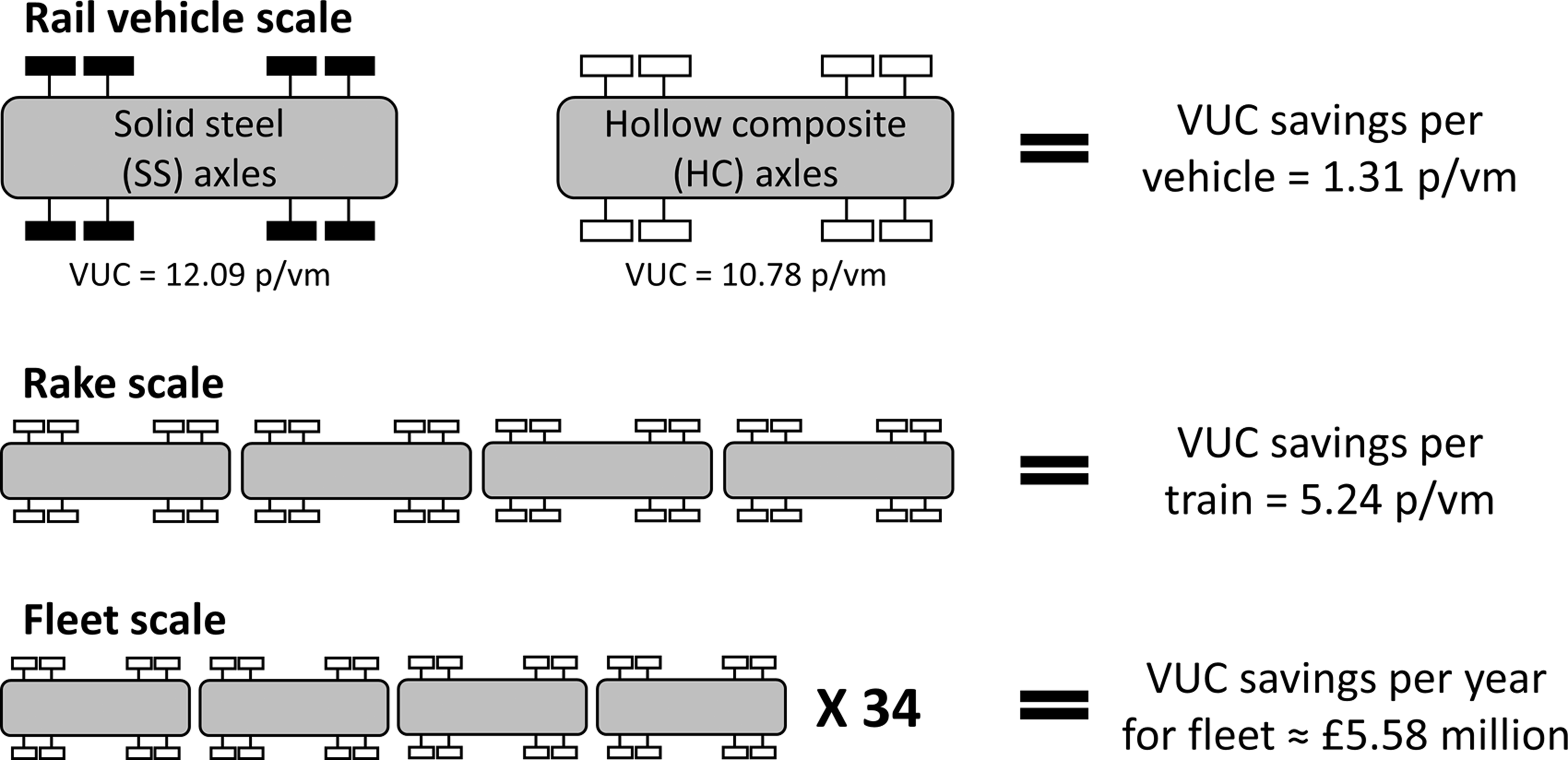
Conclusions
This paper has demonstrated the potential for lightweighting of railway axles by (1) boring out the middle of the axle to form a hollow axle and (2) material substitution. It was shown that if the outer diameter of the hollow axle is increased by 30% over that of the solid axle diameter, a mass saving of 56% is achievable for the hollow axle. It was demonstrated that a hollow axle can further be lightweighted through material substitution via a systematic approach using the CES software. Although limitations exist, the CES software proved to be a useful tool for identifying lightweight candidate materials for the axle. The candidate materials identified were all advanced composite materials based on the stated requirements, and the optimum material identified was a ‘bismaleimide matrix + carbon fibre composite.’ A hollow axle manufactured from this composite material offered 64% savings in mass when compared to an HS axle, and 84% savings in mass when compared to an SS axle.
Through the application of VUCs developed by Network Rail, the cost savings of a HC axle compared to that of a SS axle configuration was quantified for four common British rail vehicles classes discussed in this paper. It was found that the British rail motor vehicle class 390, Pendelino intercity train, offered 13% VUC savings with HC axles as opposed to SS axles. This was due to a combination of high unsprung mass and high speed of a Pendelino. Moreover, for the scenario described in this paper a potential £5.58 million could be saved per year for a 220/M Voyager rail vehicle in terms of VUCs, over the entire fleet of 34 trains (four carriages per train) by implementing HC axles. This is one example of a costing approach to support decision making with respect to the benefits of lightweighting related to the design of railway axles and reduction of unsprung mass. Moreover, the reduction of unsprung mass not only reduces VUCs, but also equates to an overall lighter design, resulting in a more track-friendly train. This helps to reduce track and infrastructure damage, reduce energy consumption, reduce total operating costs and possibly offer faster journey times.
Declaration of Conflicting Interests
The author(s) declared no potential conflicts of interest with respect to the research, authorship, and/or publication of this article.
Funding
The author(s) disclosed receipt of the following financial support for the research, authorship, and/or publication of this article: This study was supported by the Engineering and Physical Sciences Research Council through the: ‘EPSRC Future Composites Manufacturing Research Hub [Grant number: EP/P006701/1]’ and ‘EPSRC Industrial Doctorate Centre in Composites Manufacture [Grant number: EP/L015102/1].’