
Abstract
A small-scale laboratory apparatus was built to study liquid friction modifier (LFM) behavior in a top-of-rail application. A field experiment was also carried out to complement the laboratory findings. KELTRACK® (a water-based LFM) was used as the test fluid. Laser-induced fluorescence served to measure the LFM thickness left on the track after the passage of the wheel. The lab experiments show that the LFM cannot withstand the high wheel-rail contact pressure in the nip present in cargo rail situations. As a result, the liquid is squeezed out laterally and attaches to the edges of the wheel contact band. This “edge liquid” is then carried down the track on the wheel. Gravimetric measurements of the wheel contact band confirm this observation, and show that only a minute amount of liquid is carried through the nip in the valleys between surface roughness features. In the field experiment, the LFM is applied from a trackside unit on a tangent section of the track. About 500 m downstream of the application point, the track has a curved section. LFM cannot be detected anywhere on the track a short distance (∼200 m) past the application unit. However, LFM is detectable on the curved sections of the track up to approximately 2 km from the application unit. This LFM on the curved track is believed to be due to transfer of the “edge liquid” from the wheel to the track, caused by the movement of the contact band as the train rounds a curve. The presence of LFM on the curved track far downstream is consistent with prior measurements of reduced lateral force on the curved track downstream of LFM application sites.
Introduction
Top-of-rail friction control through application of liquid friction modifiers (LFM) is widely implemented in heavy haul freight railways.1,2 LFMs change the coefficient of friction between the wheel and rail to a value less than that of pure metal-to-metal contact, but are still sufficiently high to not compromise traction and braking. This reduced level of friction significantly reduces wear, curve noise, and the lateral force at the wheel-rail interface in a curve.3–8
Harmon and Lewis 9 have recently conducted a review of top-of-rail (TOR) friction modifiers. They identify a gap in the literature—the lack of a thorough understanding of carrydown. Carrydown distance is defined as the distance from the application unit to the point where the LFM’s tribological benefits are no longer noticeable. TOR products are usually applied to the track via a trackside application unit. The trackside system is recommended when a long distance of the rail is to be coated with the LFM. 9 When the wheel rolls over the LFM pool, the wet film splits between the wheel and the rail, with some remaining on the rail and some depositing on the wheel. The coated wheel then comes into contact with the rail at the next revolution, where the product is intended to be transferred back to the rail. LFMs can be water-based, oil-based, or hybrid (mixed). The water phase of LFMs has been shown to vaporize quicker than the oil phase in the wheel-rail contact (high-temperature zone), 10 changing the carrydown performance.
One device that has been used to study carrydown in a laboratory is the twin-disc machine. The details of this device, along with test protocol and instrument discussion, are outlined in Gutsulyak et al.’s study. 11 In this machine, the product is applied to the interface between two counter-rotating metal discs with an applied normal force, and the friction coefficient between the discs is measured as a function of the number of disc rotations. The variation in the friction coefficient (specifically, how long the coefficient remains below that of bare metal-to-metal contact) is then used to identify the carrydown distance. A friction modifying effect has been observed even 1000 rotations after application of the LFM to the twin discs. 1000 rotations approximately correspond to ∼3 km travel of the train with minimal slip between wheel and rail (assuming a wheel diameter of 1 m). However, twin disc machines have a dramatically smaller size than a full-scale train wheel. In addition, LFM on one disc interacts with a surface that has already been in contact with LFM, in contrast with LFM application in the field, for which LFM adhering to the first wheel interacts with the bare metal rail downstream of the application site. 12 Stanlake 13 studied the initial stage of carrydown, in which the wheel rolls over a pool of LFM, using an apparatus that consists of a ramp and a steel roller. The roller is released from a certain height and rolls over a patch of wet friction modifier at the base of the ramp. The mass of the liquid transferred to the roller was measured, and it was shown that a small change in the product formulation could lead to a drastic change in the amount of film transferred during film splitting.
Carrydown has also been studied in the field. Chiddick et al. 14 showed that the lateral force on the rail is reduced by 35% (with a decrease in wear and rolling contact fatigue) almost two miles downstream of a trackside LFM-dispensing unit. Other researchers15,16 questioned the accuracy of those handheld tribometer measurements as the friction level is also a strong function of the weather conditions and rail contamination. Khan et al. 17 directly studied LFM coverage on the wheel and the rail. They used cotton swabs to collect samples from the wheel and the rail surfaces at various distances downstream. The samples were subsequently analyzed using the energy dispersive X-ray (EDX) method, searching for LFM elements such as molybdenum (Mo) and magnesium (Mg). Those researchers were unable to detect LFM on the rail more than ∼100 m from the application site. In addition, they showed that the product could not support the high contact pressure at the wheel-rail interface and that it was pressed out of the contact band, limiting the carrydown distance. In an experimental trial, Eadie et al. 18 showed there is an optimal amount for the LFM pool, beyond which increasing the initial pool volume barely changes the carrydown distance.
Although these studies give insight into some aspects of carrydown, other aspects of carrydown are not fully understood. For instance, we do not have a complete understanding of the mechanism by which the LFM functions at the wheel-rail interface and transfers down the track. The impact of the LFM rheological properties on carrydown is another open question that requires further attention. This information is particularly important for LFM manufacturers. Additional information is also needed to optimize the unit spacing and the application rate of the wayside systems. Motivated by these gaps in the literature, this research aims to enhance our understanding of the carrydown mechanism. The research comprises two parts: laboratory studies on a novel apparatus that mimics key aspects of realistic rail conditions, and field trials on an operating track. In the Methodology section, we describe the methodology for both types of experiments, and in the Results and Discussion section, we present the results and draw parallels between the laboratory studies and the field trials. Finally, in the Conclusions section we summarize the key findings and make recommendations for future work.
Methodology
Lab experiments
A custom rig (Figure 1) was developed at the laboratory scale to understand the LFM behavior at the wheel-rail interface and the mechanism for subsequent carrydown. The apparatus was not intended to accurately mimic all aspects of the full-scale wheel-rail contact, but rather represents a simplified geometry that is governed by the same physics. It consists of a highly modified woodworking band saw, chosen because the band saw provides a long and continuous moving surface. The original band saw was modified to incorporate various wheels, motors, pneumatic air cylinders, and sensors to model the wheel-rail contact and collect experimental data. The band saw blade represents the top surface of the rail. The blade is made of carbon steel and is 0.9 mm thick. To reduce the light reflection from the surface of the band saw blade (which is a requirement for the film thickness measurement technique, described next), the blade was chemically treated with black oxide. The treated blade has an RMS roughness of ∼850 nm (measured with an optical profilometer), close to the railhead’s typical roughness of Schematic of the laboratory apparatus. The wheel represents the train wheel, and the blade represents the rail. An air cylinder applies a large normal load to the wheel. Various sensors are in place to measure the gap size, the speeds, and the applied load.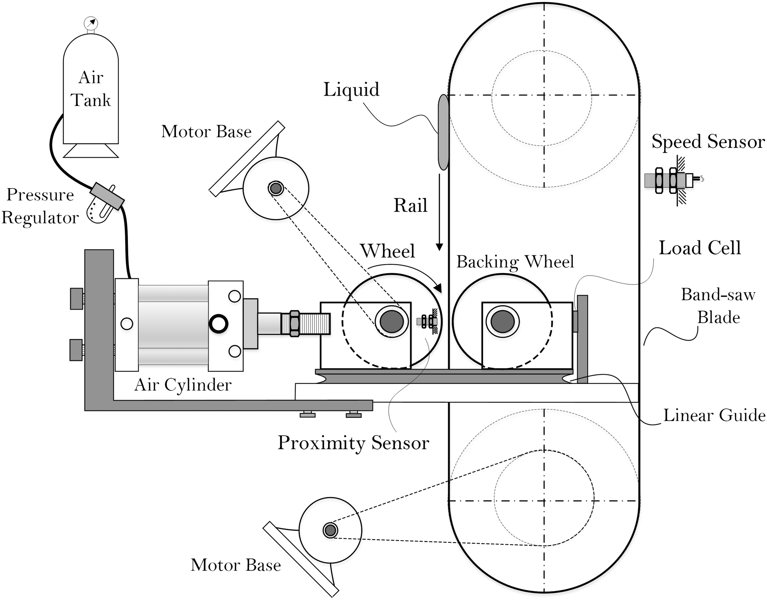
The wheel design was based on the work conducted by Naeimi et al.,
20
where they showed that a 1/5-scale train wheel under scaled loading could produce a contact pressure comparable to that at the wheel-rail interface. The wheel diameter is 0.2 m (roughly 1/5 of the actual wheel diameter). The wheel was driven by a separate motor than the blade to allow for independent speed control over the blade and the wheel, although in the tests described here the two surface speeds are the same (i.e., there is no creepage). Two magnetic Hall effect sensors were used to measure the speed of the blade and the wheel. A normal force was applied to the wheel by means of pneumatic air cylinders that are controlled by fast-acting solenoid valves. A backing wheel, which spins freely on its axle, was mounted opposite the driven wheel behind the blade, and was present to prevent deflection of the blade under the applied normal load. Both wheels were mounted on a linear rail guide to ensure smooth and accurate activation. A 12-kN load cell measured the normal force at the wheel-rail contact patch. The load cell measures the load on the wheel, and using Hertzian contact theory, the contact pressure at the wheel-rail contact is approximated, given Young’s modulus and Poisson’s ratio for mild steel (
The wheel and rail geometries do not match the commercial geometries in some regards. The blade was flat, unlike the crowned cross-section of a railhead.
22
Three wheels, which approximate railroad wheels, were fabricated from mild steel (grade AISI 1018 with surface hardness of Rockwell B). One wheel has no crowning (i.e., it is a simple cylinder), one has a constant crowning radius of
Water-based KELTRACK is the test fluid. It is a non-Newtonian fluid exhibiting shear thinning and elastic behavior with the measured viscosity of
Carrydown measurements
The thickness of the LFM layer deposited on the blade after the passage of the wheel, which is indicative of the amount of carrydown, is on the order of 100
The LIF signal must first be calibrated against a standard. Shadowgraphy measurements of droplets of various sizes were chosen as the standard. The LIF signal is linearly (
Field experiments
Field experiments were performed on a track located in Delta, BC, Canada. The track was limited to freight and maintenance trains. A wayside unit (Figure 2) was installed on a tangent track located about 500 m upstream of the curved track. An applicator bar (visible in Figure 2(b) and (c)) was used to distribute the LFM on the railhead. The wayside unit was equipped with a magnetic sensor to detect train wheels. The sensor counted the number of passing axles, and for every seven axles, the unit pumped 2.8 mL of LFM onto the track, consistent with the supplier’s recommendations (note that the application rate depends on the track curvature, traffic, unit spacing, and product, and may be different for different formulations of KELTRACK). The same dyed LFM used in the laboratory experiments was also used in the field experiments. An overview of the track along with the relevant distances from the application unit is presented in Figure 3. (a) Wayside top-of-rail application unit, (b) distributed liquid friction modifier on the rail utilizing two applicator bars, and (c) application site after the passage of the train. A top view of the studied track showing the location of the application unit, different phases of the trial, the relevant distances, and the observation regions. The shallow curve starts at about 450 m from the application site and the sharp curve extends to about 2 km downstream. Image source: google earth, 33MF+V7 Delta, British Columbia (49°05'05.0"N 122°55'36.5"W) [June 18, 2021].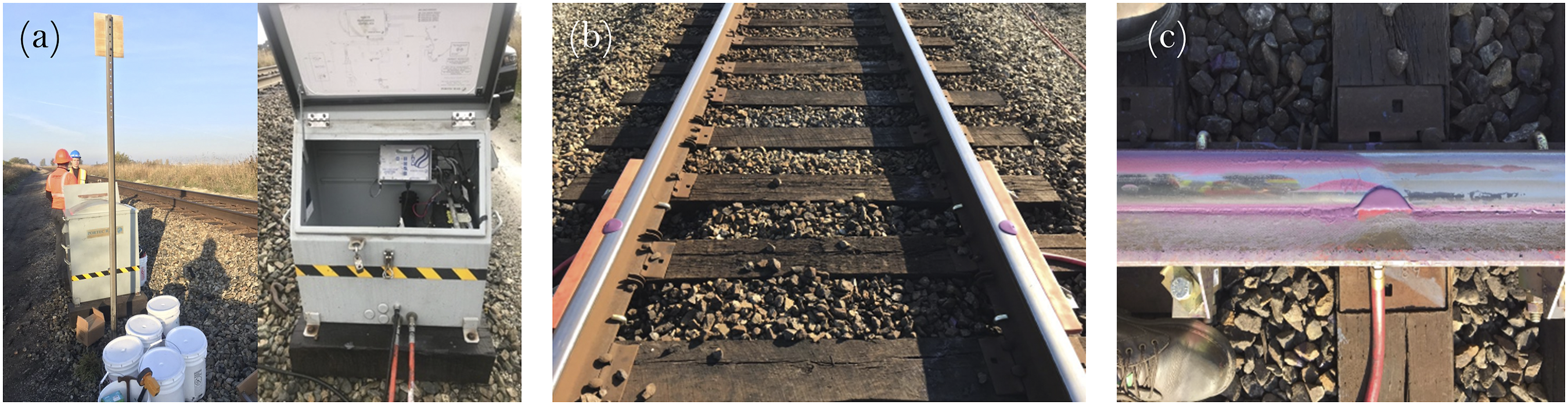
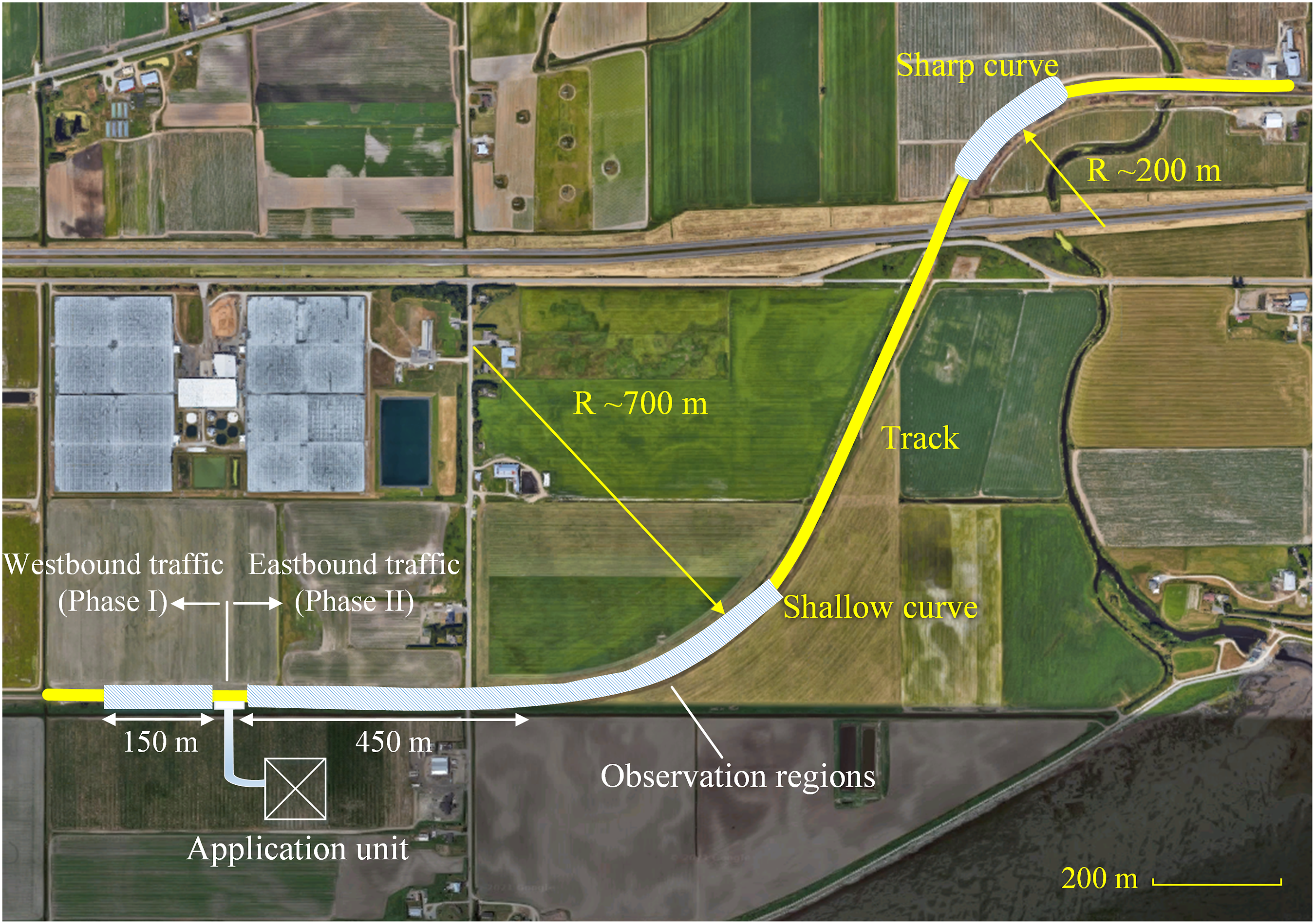
Experiments were conducted in two trials. In the first trial, Phase I, the westbound traffic (tangent track) was studied up to 150 m downstream from the application site under two conditions. In one condition, the application of dyed LFM coincided with the start of the trial. In other words, a single train with 628 axles carried the product downstream prior to measurement of carrydown. In a second condition, the track was pre-conditioned with LFM for several days before measurements of LFM on the track. During the conditioning period, approximately 33,000 train axles passed over the LFM pool. During this period, the application unit was in operation, so about 13 L of LFM were applied to the track during conditioning. In the second trial, Phase II, the eastbound traffic (both tangent and curved tracks) was studied up to almost 2 km from the application site when the track was pre-conditioned with approximately 40,000 axles. A handheld portable tribometer (Salient Systems) was used to measure the coefficient of friction along the track. We only investigated the LFM coverage on the rail, as it was not possible to stop the train to measure LFM adhering to the wheels.
Imaging of the LFM on the tracks after the passage of the train was done using a portable version of the experimental LIF apparatus used in the laboratory. The portable setup (Figure 4(b) and (c)) was clamped to the rail and imaged the track at different distances downstream of the application unit. Since no electricity was available on site, two car batteries, coupled with an inverter, were used to power the laser, camera, and computer. For the LIF setup to work properly, one needs to eliminate the ambient light, as it would otherwise interfere with the collected LIF signal. Accordingly, the whole optical setup was fully enclosed and covered by a dark cloth. (a) Schematic of the LIF setup used to measure the thickness of the carrydown LFM. (b) and (c) The portable LIF setup built to measure the LFM thickness on the rail.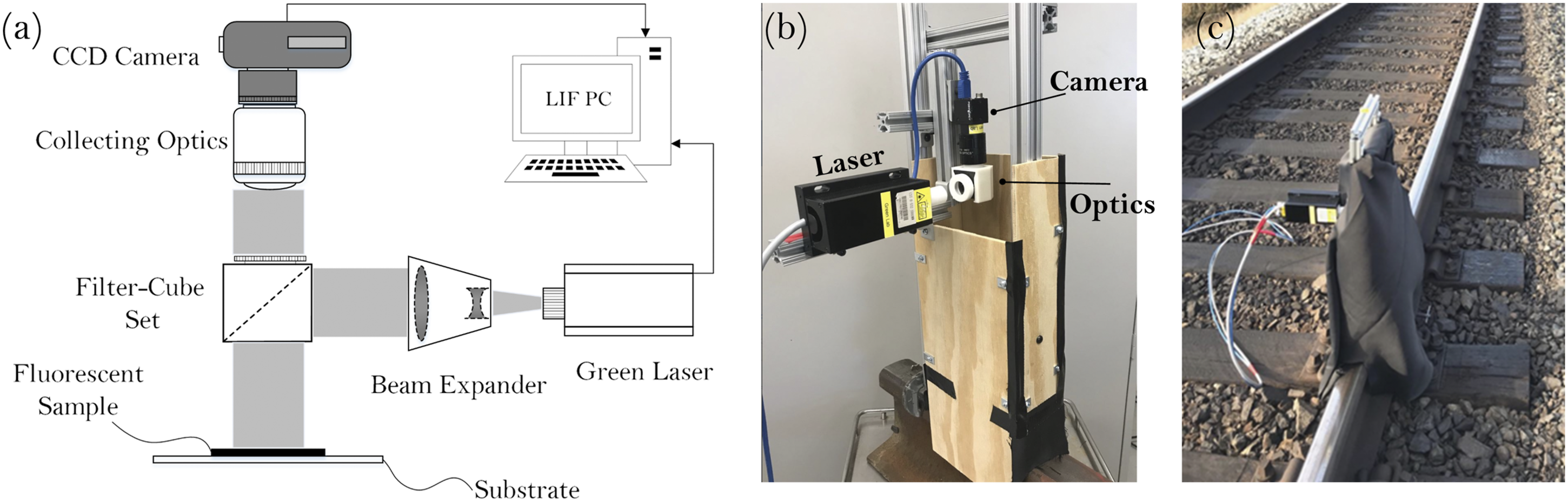
Results and discussion
Lab experiments
First, we present results for the cylindrical wheel. Henceforth, we refer to the location where the wheel rolls over the original LFM pool as Interaction One. Interactions Two to Five may show carrydown from LFM that adhered to the wheel during Interaction One. Throughout this paper, the Hertzian contact model is used to estimate the wheel-rail contact pressures. For a very lightly loaded wheel, with a Hertzian contact pressure Examples of the deposited film on the track under (a) an unrealistically low applied load L/W = 9.2 kN/m (Hertzian contact pressure of P = 46 MPa and (b) a heavy applied load L/W = 450 kN/m (Hertzian contact pressure of P = 420 MPa). Note that even under the heavy load, the contact pressure is still lower than that present in freight wheel-rail interaction. Left panels show Interaction One (initial pickup), and right panels show the subsequent carrydown. The initial pool length and depth are 4 cm and 500 μm, respectively. U = 28.8 km/hr, W = 1 cm.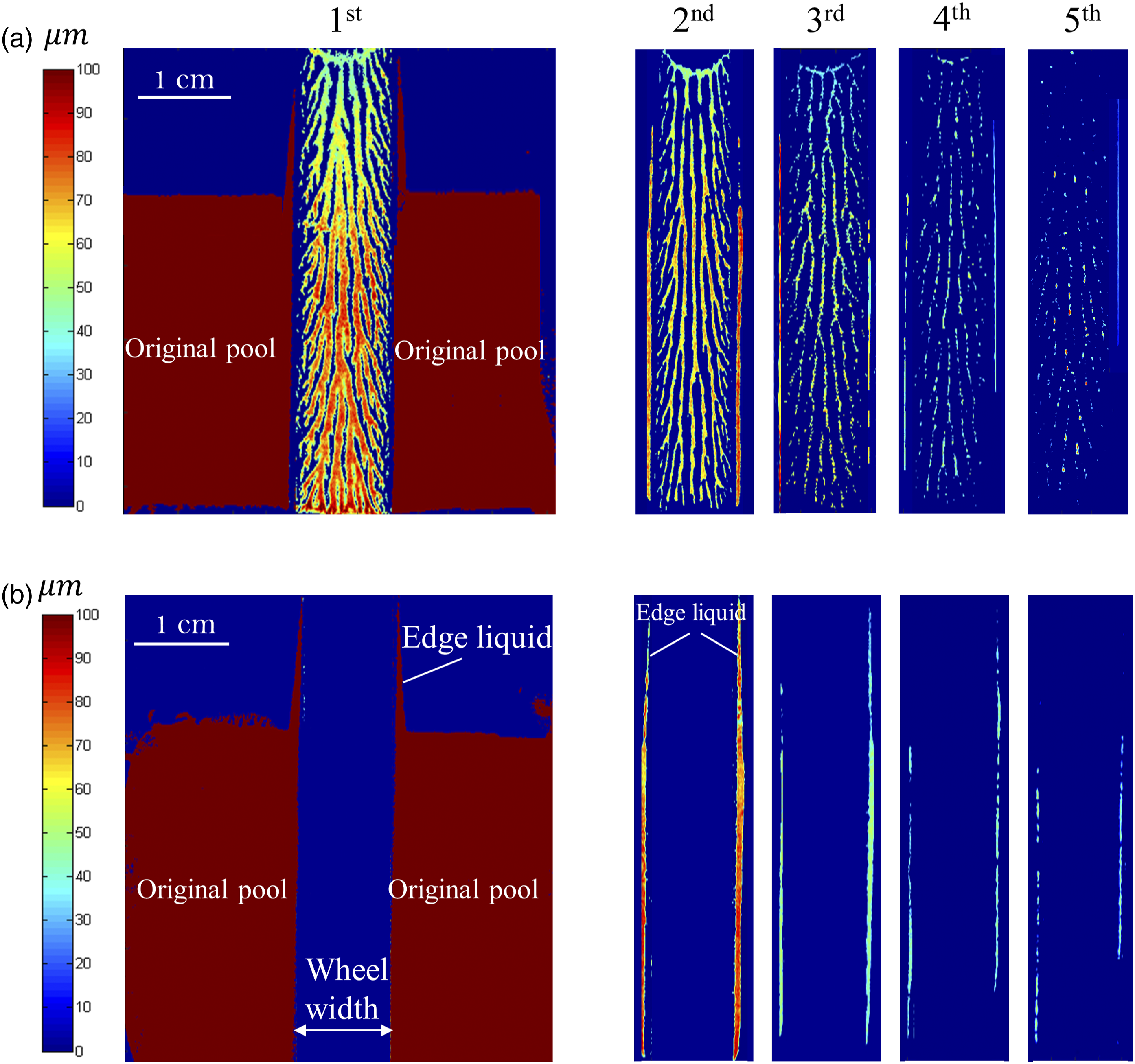
Figure 5(b) shows similar contours but for test conditions comparable to those in the real application. In the contact band, it is evident that the maximum thickness of the LFM layer is less than the 3.4-μm detection limit of the LIF system. The vast majority of the LFM, originally located in the contact band, cannot withstand the high contact pressure and is squeezed out of the nip laterally, where some of it adheres to the edges of the wheel. It is also apparent that some LFM is plowed ahead of the wheel as the wheel rolls over the pool, resulting in the two thin wedges of LFM (labeled as “Edge liquid”) extending downstream from the original pool. This edge liquid, in addition to the edge liquid picked up by the wheel as it passes through the original length of the pool, is carried forward on the rotating wheel, and some of it redeposits on the blade during subsequent interactions (apparent as two distinctive stripes on either side of the running band in Figure 5(b) right panels). The carried-down liquid reduces in depth with each interaction, weakening the observed pattern.
We posit that a minuscule amount of LFM passes through the nip in the valleys between surface roughness features (the rail surface has an RMS roughness of ∼850 nanometers). This scale is certainly below the detection limit of the LIF measurement technique. To test this hypothesis, gravimetric measurements were performed. Aluminum strips were attached to the wheel and the blade, and the samples were collected before and after each wheel-rail interaction. Subsequently, the samples were weighed carefully using an accurate analytical balance. An analytical balance with a readability of 0.01 mg was used for these measurements. These measurements were very sensitive, and special precautions were taken for accurate sample weighing. The samples were never touched with bare hands, and a pair of clean forceps was used to handle the samples. The balance was positioned on a horizontal surface, and the weighing chamber was in place to prevent the extremely small samples from being affected by air currents. The balance must be in a vibration-free environment. In addition, several experiments (with no product applied) confirmed that the weight of the bare strip is unaffected by the passage of the wheel (i.e., possible wear) and the adhesive used to hold the strip in place.
For Interaction Two, the gravimetric measurements consistently showed an increase in the strip mass of Coefficient of friction measured in a twin-disc testing machine as a function of number of contacts (number of revolutions) for dry contact (baseline) and when 37 mg of the product is applied to the disc interface. The vertical dashed-line shows the approximate number of revolutions after which the laser-induced fluorescence signal becomes undetectable. The speed of the discs and the contact pressure were set to be 500 rpm and 1 GPa, respectively.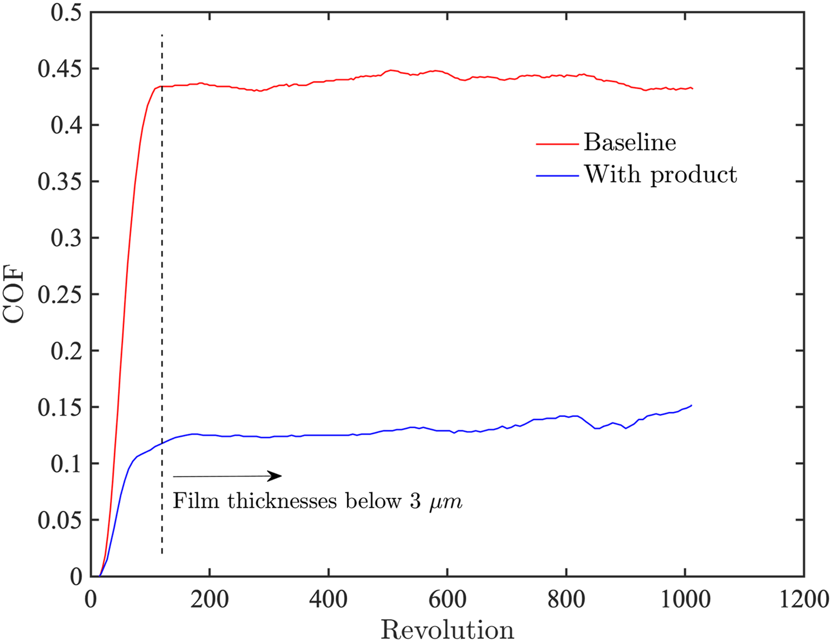
Figure 7 shows the track left by the passage through the LFM pool of crowned wheels of width 20 mm. In (a) and (b), we show the results for the crowned wheel with (a) A typical example of the measured film on the rail after the passage of the crowned wheel of Rc = 200 mm. (b) Corresponding film thickness variations across the wheel width for Rc = 200 mm (inset: experiments with higher dye concentration for test conditions U = 28.8 km/hr and L/W = 9.2 kN/m). (c) and (d) Respective graphs for Rc = 400 mm.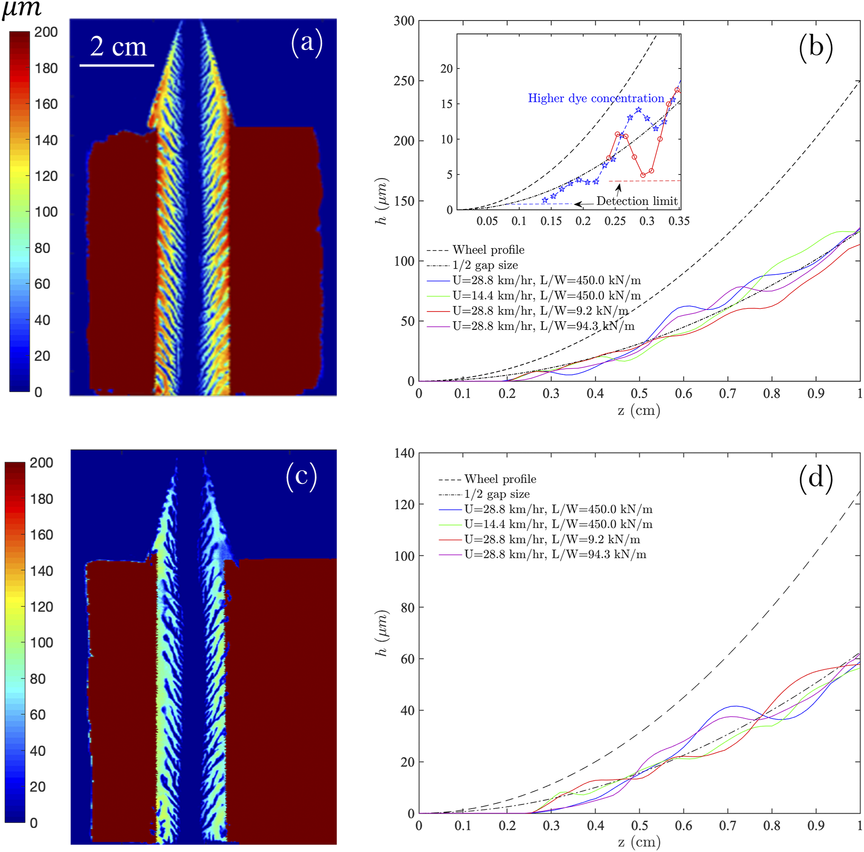
The lateral distribution of LFM film thickness is plotted for various speeds and loading cases in Figures 7(b) and (d). In these plots, film thicknesses are averaged in two steps. First, thicknesses are averaged in the direction of wheel motion. The resulting thicknesses are then additionally averaged over stripes symmetrically located on either side of the wheel centerline; therefore, the abscissa goes from z = 0 (wheel centerline) to z = 1 cm (wheel edge) for these wheels of width W = 2 cm. There is good agreement between the deposited film thickness and the dash-dot line representing half the gap size, which implies that the liquid filling the gap between the wheel and blade splits approximately 50:50.
Within a distance of 2 mm on either side of the wheel centerline, no LFM was detected. We conducted experiments with a higher tracer dye concentration (Figure 7(b) inset) to explore this region. The higher concentration improved the detection limit to
We could detect no carrydown from the crowned wheels, even with the high dye concentration. We posit that since the film splits evenly between the wheel and blade, the LFM adhering to the wheel is insufficiently thick to bridge the gap to the blade, and hence, there is no transfer back to the blade.
Field experiments
Phase I
In Phase I, the tangent track was studied up to 150 m from the application site to the west. Figure 8 displays coated rail images at various distances down the track. In this figure, the rail was pre-conditioned with approximately 33,000 axles. Similar images of the rail were also observed after passage of the first train with no pre-conditioning (not shown here, but film thickness data are plotted in Figure 9). It is clear that in most of the contact bands, the thickness of LFM is below the detection threshold of the experimental technique (about 3 µm). Within the contact band, the product is mostly visible in the grooves and cavities of the surface. We see a repeating pattern in all images: a minute amount of LFM on the contact band but significant carrydown of fluids from the edge of the contact band. We hypothesize that this carrydown on the (crowned) train wheels is due to modest changes in the location of the contact band, for example, due to lateral motion of the train or due to the variable geometry of different wheels. Deposited liquid friction modifier on the rail at various distances from the top-of-rail application unit. The rail was pre-conditioned for three days with 33000 axles. Liquid friction modifier film thickness on the rail at various distances from the application unit averaged over (a) entire railhead and (b) contact band.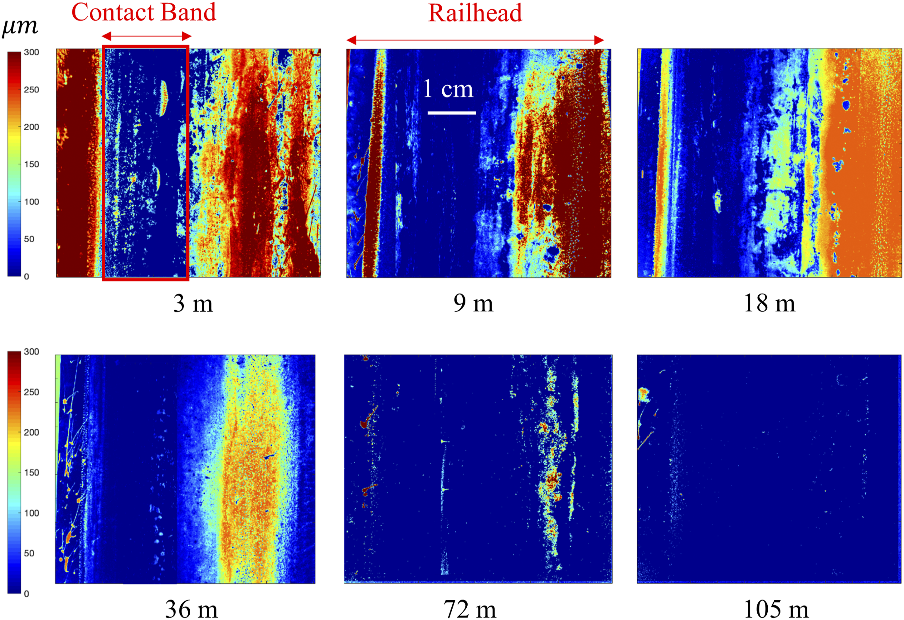
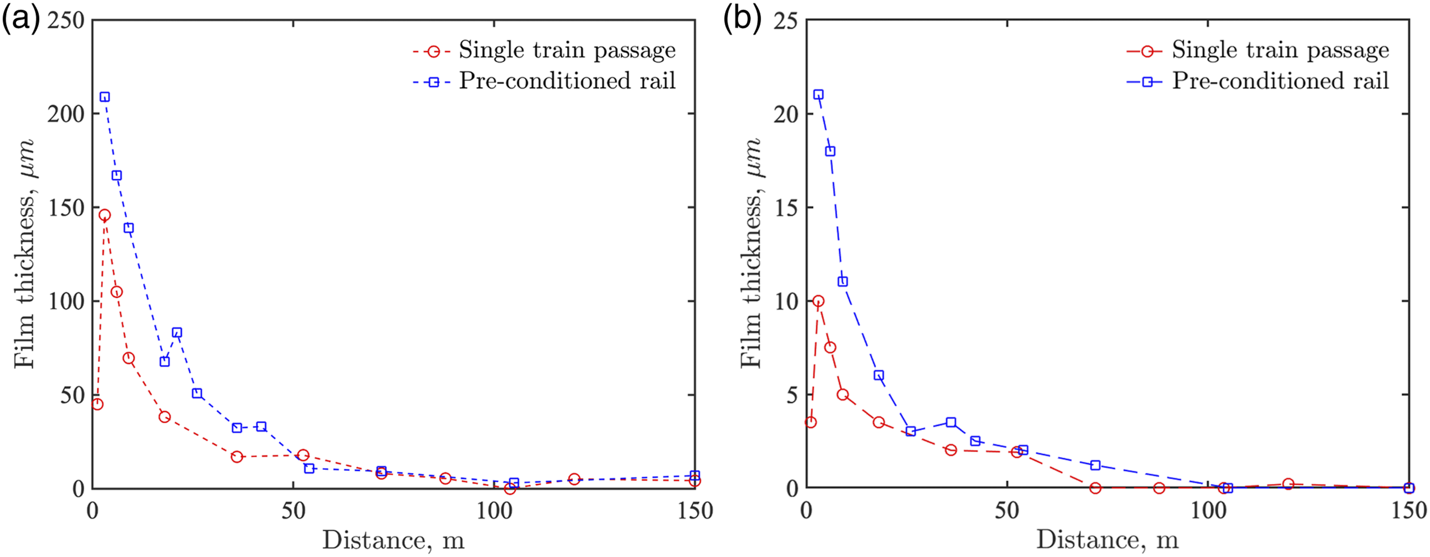
Figure 9 presents the average measured film thickness as a function of the distance from the application unit for both single train passage and pre-conditioned rails. With the measurement system, it is possible to differentiate the LFM on the contact band from other parts of the railhead. Averaged over the entire top of the rail (Figure 9(a)), the LFM is present over the entire scanning distance (∼150 m, corresponding to the 47th wheel-rail interaction, assuming that the wheel diameter is 1 m). However, according to Figure 9(b), on the contact band, the carrydown distance is limited to approximately 100 m. When the rail is pre-conditioned, the FM is often detected for slightly longer distances, which is intuitive. The magnitude of the film thickness and the approximate way in which it varies with distance from the application unit are consistent with the findings of Khan et al., 17 who reported the deposited film thickness on the wheel contact band. However, it is unclear whether those authors studied the carrydown on a previously clean rail or a pre-conditioned rail. When interpreting these results, the detection limit of the measurement technique must be considered. For instance, after ∼150 m on the track, an undetectable fluorescence signal does not necessarily mean the complete absence of the LFM. As discussed above, the product may be present on the track if the thicknesses are below the detection limit.
Phase II
In this phase, the tangent and curved tracks were studied up to 2 km eastbound from the TOR application unit. The tangent track extends from the application unit to ∼450 m downstream, followed by two curved tracks extending to approximately 2 km downstream. For all tests, the rail was pre-conditioned with approximately 40,000 axles. Similar to Phase I, LFM was detected on the rail up to about 200 m from the TOR application unit. After that, no product was detectable on the rail until the end of the tangent section. Upon entering the curved section of the track, the LFM can again be measured on the railhead, which was a surprising finding. Some sample images of the LFM detected on the curved tracks are shown in Figure 10, and the LFM thicknesses are plotted in Figure 11. Although the average thickness of the LFM present on the curve is typically less than Images of liquid friction modifier detected on the (a) shallow curve and (b) sharp curve for various downstream distances. Liquid friction modifier film thickness (primary axis) and CoF (secondary axis) at various distances for both tangent and curved tracks. The vertical dashed line shows where the curved track starts.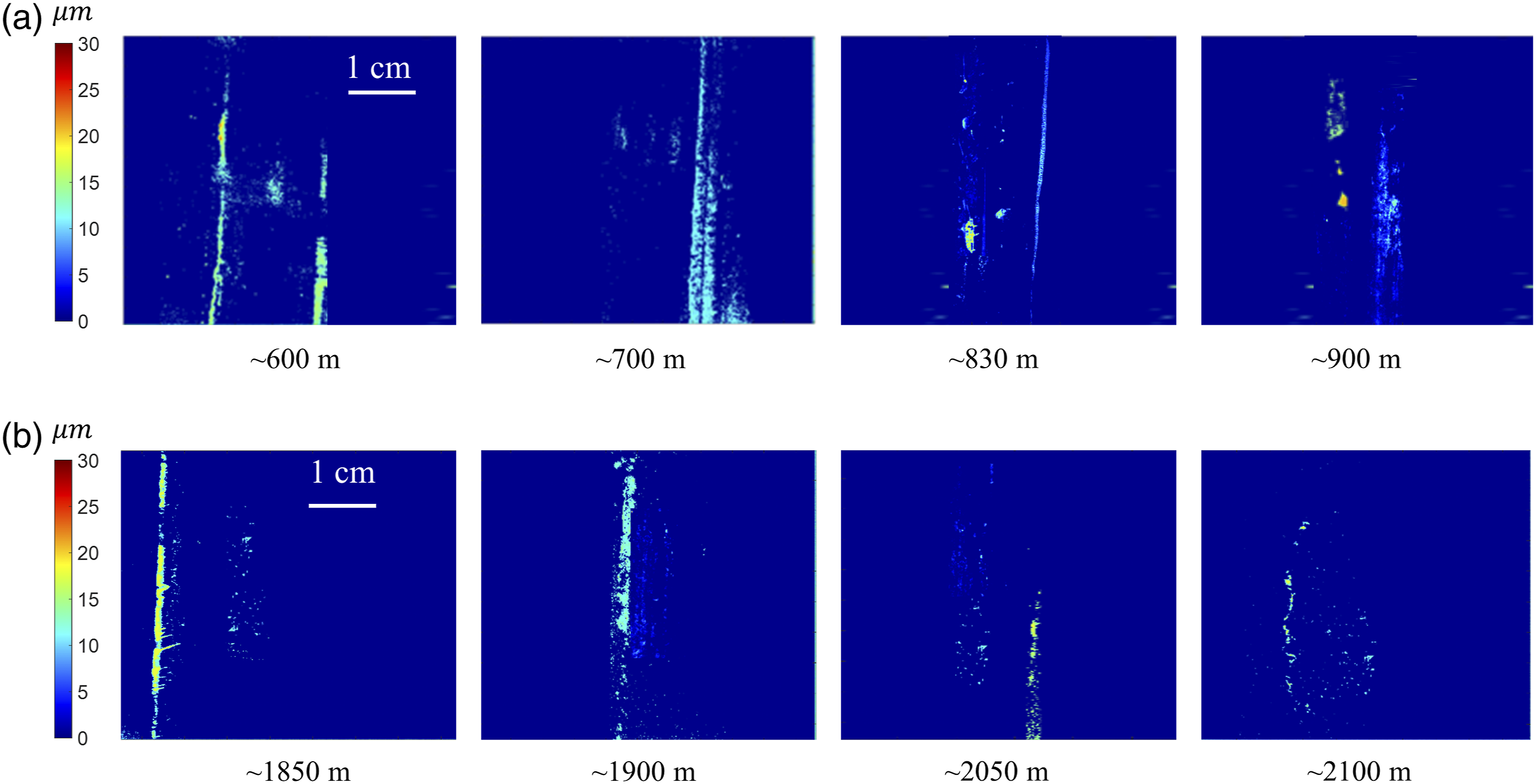
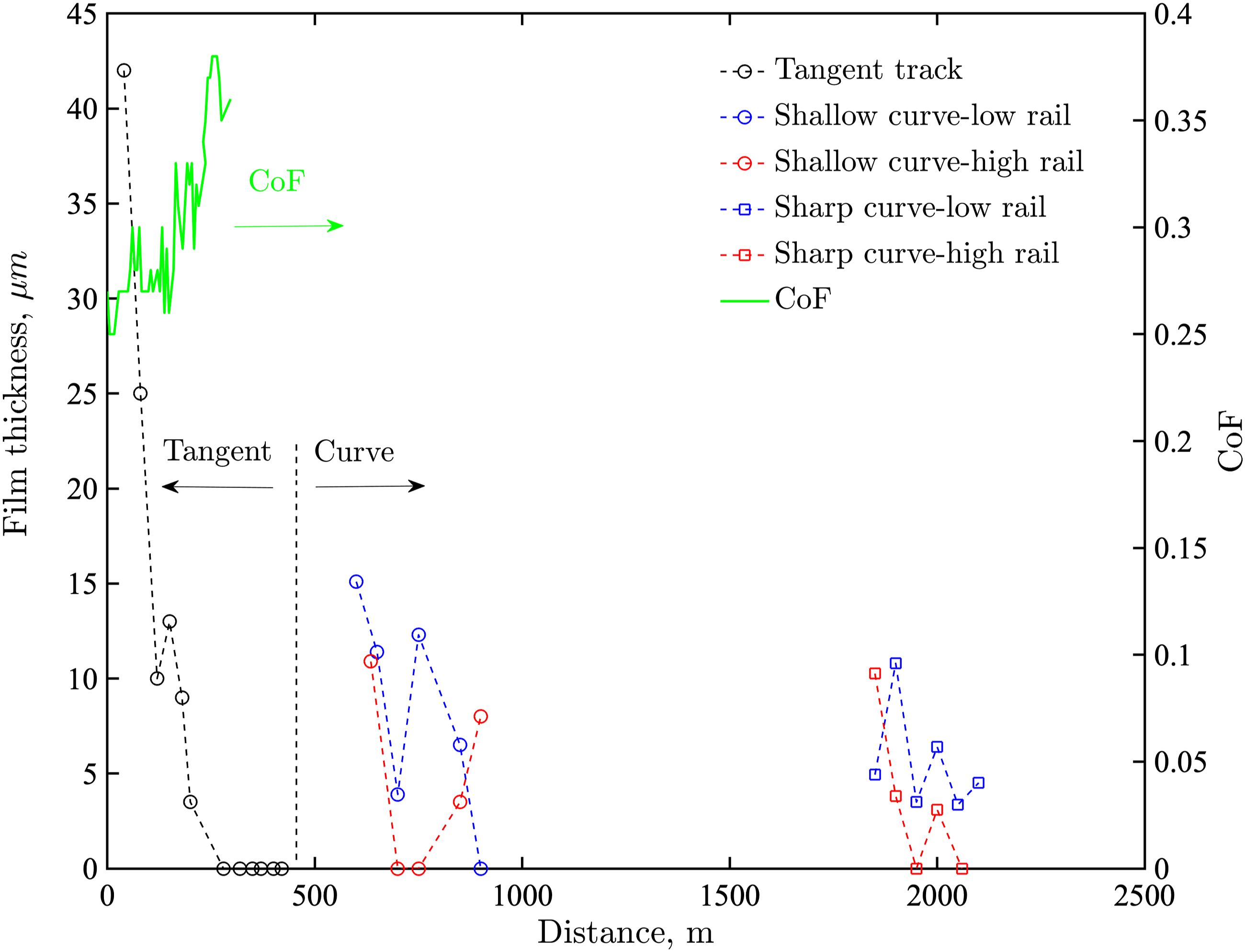
The surprising finding of LFM on the railhead on the curved track more than a kilometer downstream of where it was last observed on the tangent track requires an explanation. We hypothesize that as each wheel passes through the LFM pool at the application site, LFM is pressed out of the running band and adheres to the wheel adjacent to the running band. As the bogie hunts or sways on the tangent track, small excursions of the location of the running band on the wheel deposit the LFM onto the rail immediately adjacent to the running band. However, after a few hundred meters of motion, all the LFM near the nominal running band that can be transferred to the track has transferred, and none remains on the wheel at the edges of its tangent running band. However, when the bogie rounds a curve, centrifugal forces combined with wheel conicity substantially change the running band location, bringing fresh LFM into contact with the track, where it is deposited. This hypothesis is consistent with the experiments of Khan et al., 17 who showed that LFM stays on the wheel for a distance longer than 3 km.
Conclusions
Laboratory and field experiments were carried out to study water-based TOR-LFM (KELTRACK) behavior at the wheel-rail interface and the associated carrydown. An optical technique, based on the fluorescence of a tracer dye, was used to scan the rail and generate a map of the film thickness. The key findings of this research are as follows: 1. Both laboratory and field experiments clearly show that the LFM cannot withstand the characteristic high contact pressure at the wheel-rail interface to form a lubrication layer. Therefore, the LFM is pressed out of the contact band in locations where the wheel and rail are smooth. This liquid adheres to the non-contact surface of the wheel. Careful gravimetric measurements show that unless there are significant surface irregularities, only a minute amount of LFM is carried through the nip. This LFM is believed to be carried in the valleys between surface roughness features. 2. The LIF technique is used throughout this study to detect and measure the deposited liquid on the rail. This technique has a detection limit of about 3. At a significantly lower contact pressure, the hydrodynamic pressure developed in the fluid is sufficient to balance the wheel load. However, this low-pressure condition is not expected to occur in practice for loaded or even empty freight trains. 4. The LFM adhering to the non-contact surface of the wheel can subsequently be transferred to the track if the location of the contact band on the wheel changes, for example, due to hunting or sway. 5. LFM has been measured on the tangent track for a distance up to ∼200 metres from the application unit. On the contact band, however, this distance is limited to ∼70 metres. LFM can be detected in track curves up to 2 kilometres from the application unit. The presence of LFM on curved track kilometers from the application unit is thought to be due to the lateral movement of the contact band as each bogie rounds a curve. Whether that small amount of product on the curved track can provide frictional benefits requires further investigation, but prior measurements of significant lateral force reduction 2 miles down from the application unit are an indication that this product transfer could prove useful. 6. It is also important to note that product layers thinner than the detection limit may reduce friction between the wheel and rail, as confirmed by the twin disc experiments. In addition, this study is only limited to rail coverage. Train wheels are capable of carrying products for longer distances.
In future work, it would be interesting to measure the spatial distribution of LFM coverage on the wheel, perhaps using LIF. Performing field experiments for an oil-based FM would aid in understanding the role of liquid evaporation on carrydown. Finally, carrying out additional laboratory experiments with fluids of different properties (e.g., shear thinning and elastic) would elucidate the role of non-Newtonian fluid behavior on carrydown.
Footnotes
Acknowledgments
We thank LB Foster and NSERC for their financial support of this research. This research was undertaken, in part, thanks to funding from the Canada Research Chairs program.
Declaration of conflicting interests
The author(s) declared no potential conflicts of interest with respect to the research, authorship, and/or publication of this article.
Funding
The author(s) received no financial support for the research, authorship, and/or publication of this article.