
Abstract
The recent tendency to reduce the weight of car bodies is posing a new challenge to vertical ride quality, since the vibrations related to car-body vertical bending modes affect heavily passengers’ comfort and cannot be fully mitigated by conventional vehicle suspensions. In this work, four mechatronic suspensions, considering active and semi-active technologies in secondary and primary suspensions, are compared to show their relative merits. LQG and H∞ model-based control strategies are established in a consistent way for each suspension scheme to perform a comparative assessment of the four concepts on objective grounds. A two-dimensional 9-DOF vehicle model is firstly built, using a simplified representation of car-body bending modes; this model is also used to design the model-based controllers. The comparison of the four mechatronic suspension schemes based on the 9-DOF model shows that full-active secondary suspension is the most effective solution whilst semi-active primary suspension is also effective in terms of mitigating car-body bending vibration. Then, a three-dimensional flexible multibody system (FMBS) vehicle model integrated with a finite-element car-body is considered to allow a more detailed consideration of the vehicle’s vibrating behaviour. The results of the FMBS model show a good agreement to the results of the 9-DOF model and the relative merits of the four mechatronic suspension schemes as found from the previous analysis are basically confirmed, although the FMBS model is more suited for a quantitative assessment of ride quality.
Keywords
Introduction
Active and semi-active control technologies can be used to improve the performance of railway vehicles under different respects including stability, curving behaviour and ride quality.1,2 As far as the improvement of ride quality is concerned, active lateral suspensions have been successfully implemented in Japan and Europe, while in some other countries full-scale tests have been carried in the line or on roller rigs. 3 By contrast, active vertical suspensions received so far relatively less attention, and this is possibly due to the fact that pneumatic secondary suspensions in use in most modern-generation passenger trains are capable of providing an adequate level of ride quality in most service scenarios. However, the recent tendency to reduce the weight of car bodies is posing a new challenge to ensuring proper ride quality levels, as the lighter car bodies are more prone to vibrations involving their vertical bending modes in a frequency range relevant to ride quality,4,5 which can hardly be controlled by passive suspensions whilst mechatronic suspensions can be effective with controlling the narrow band of excitation related to selected car-body modes. 6
Previous research concerned with active and semi-active vertical suspensions for railway vehicles is summarized hereinafter. Goodall built a simplified rigid vehicle model and compared the effectiveness of the full active and semi-active control for vertical secondary suspension, showing that, active and semi-active suspensions can respectively achieve 50% and 34% improvement, in terms of reduction of RMS acceleration. 7 In Sweden, the active vertical secondary suspension was tested on Regina 250 with the speed up to 200 km/h, where the passive vertical dampers between car-bodies and bogies are replaced by actuators. 8 Skyhook control is integrated with mode separation so that car-body bounce, pitch and roll motions are controlled separately. The vibrations coming from both car-body rigid vibrations and structural vibrations are improved.
The above-mentioned investigations focus on car-body rigid vibrations. However, in case the objective is to reduce vibration caused by car-body flexibility, the control strategies are quite different. One method is to implement piezoelectric actuators,9,10 in which strain sensors measure structural vibration and then the bending moment required to attenuate car-body vibration is generated by piezoelectric actuators. Foo and Goodall explored the use of a classic active secondary suspension with Skyhook controller, showing a limited reduction of car-body structural vibration. The same authors introduced an actively-controlled mass-damper structure attached to the car-body which proves more effective to suppress the bending mode. 11 References12,13 adopt the same approach through a properly designed passive or semi-active suspension for the electrical converter attached to the car-body underfloor. Sugahara proposed to use semi-active primary suspension to improve the car-body bending modes6,14,15 for a high-speed train running on Shinkansen line at speeds up to 300 km/h, as well as for a meter-gauged vehicle with the maximum speed at 100 km/h. Although primary suspension is rarely considered for improving ride quality, the simulations and field tests by Sugahara demonstrate the effectiveness of this scheme.
The state-of-art analysis above shows that many different approaches can be successful in controlling the vertical vibration of the car-body in relation to its rigid and flexible modes. Full-active and semi-active suspensions can both be used, and mechatronic components can be included both in the primary and secondary suspensions. Therefore, four main schemes can be devised: active primary, semi-active primary, active secondary and semi-active secondary suspensions. Although there may be practical reasons for choosing one or another of these schemes, it is important to investigate the relative merits of each one of these solutions.
The aim of this paper is therefore to perform an objective comparison of the benefits of each one of the above schemes that can be hopefully used as a basis to drive the design of future mechatronic suspension concepts and to identify new solutions not addressed by previous research work. To this aim, the case of a trailer vehicle designed for a maximum speed of 120 km/h is analysed. The control strategies considered in this study are linear quadratic Gaussian (LQG) and H∞, as they both allow to define the objectives of the mechatronic suspension in a way that enables an objective comparison of the active and semi-active suspension schemes. Based on the use of these two control strategies, the same control target is defined for all suspension schemes, i.e. to minimize a weighted sum of the car-body accelerations measured at front, centre and rear positions and of the control force. In this way, the performance of the four suspension schemes can be directly compared.
Initial analyses are performed using a simplified vehicle model with 9 degrees of freedom (DOF) and a systematic comparison of the different suspension schemes is worked out thanks to the low computational effort required by this model. Both LQG and H∞ are applied on the simplified model to show the improvement of ride comfort that can be achieved using different suspension schemes for an ideal case in which the design of the controller involves no modelling error or uncertainty. Then, a more detailed flexible multi-body system (FMBS) model of the same vehicle is used to consider in more depth the effect of car-body flexibility, as well as the influence of some specific features of the vehicle’s suspensions that cannot be represented to the desired level of accuracy by the simplified model. For the FMBS analysis, the H∞ controller is adopted to evaluate the performance of candidate suspension schemes, in view of analysing the applicability of the schemes in a real application.
Rail vehicle dynamic models
Simplified 9-DOF vehicle model
In this study, a simplified 9-DOF vehicle model is firstly considered, see Figure 1. This model considers the bounce and pitch motions of the car-body(coordinates
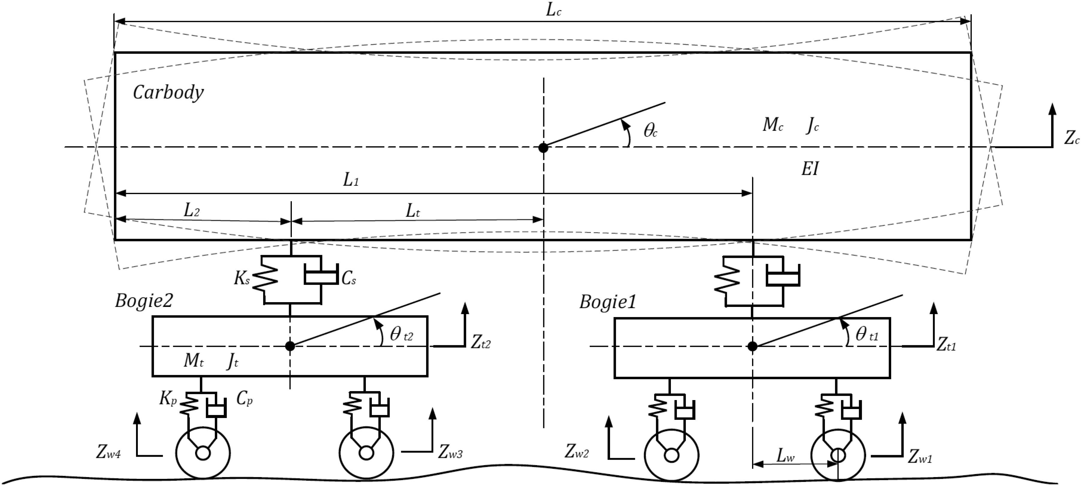
The 9-DOF of vehicle model.
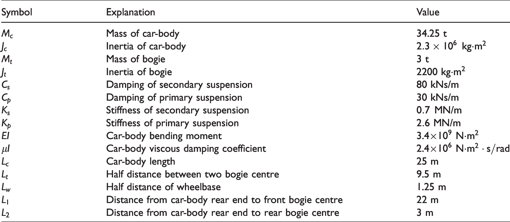
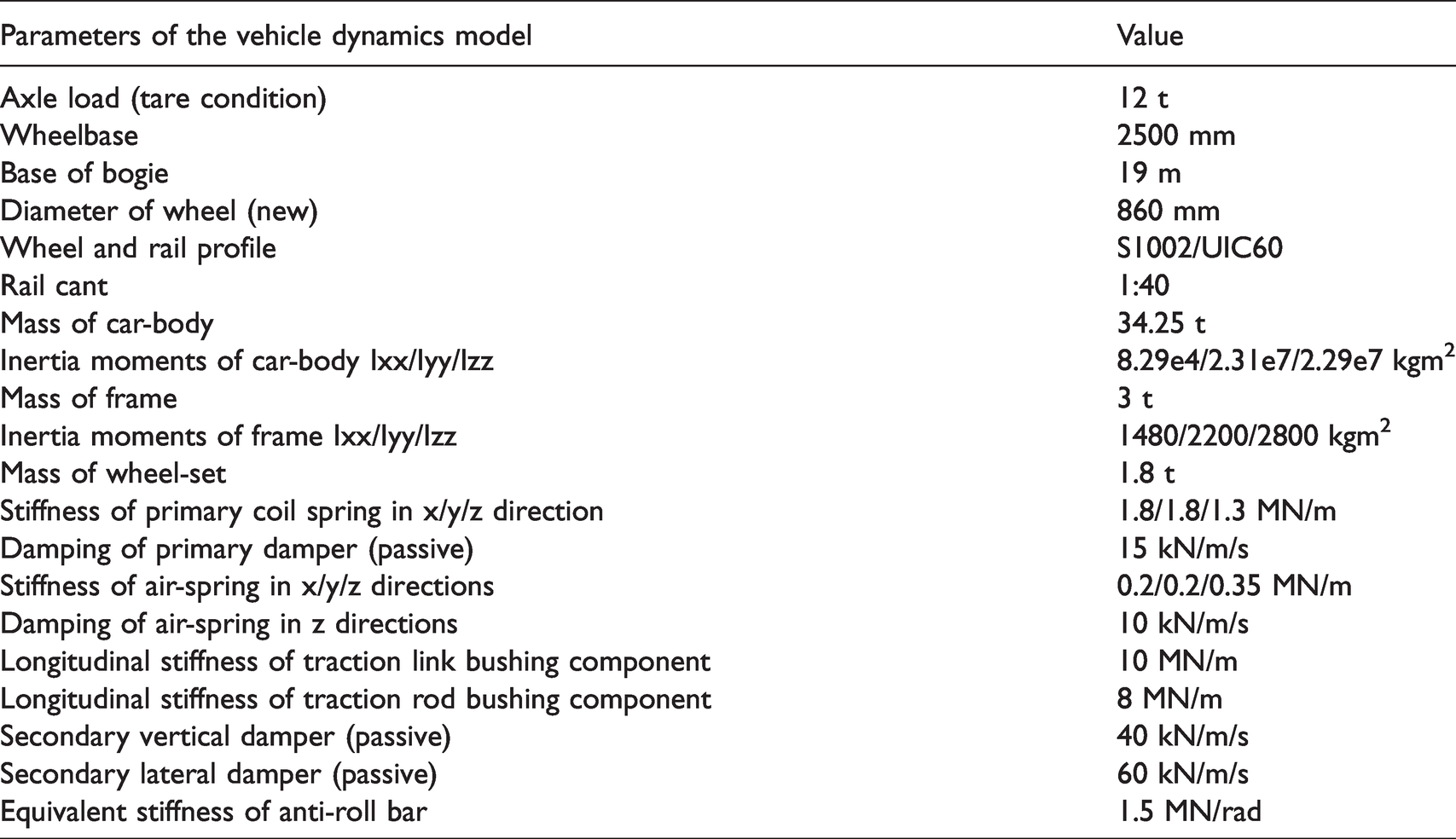
The values of the physical parameters of the 9-DOF model are listed in Table 1 using the nomenclature introduced in Figure 1. These parameters are chosen to produce a simplified representation of the FMBS vehicle model introduced in the following section.
Parameters of 9-DOF model.
The first three car-body bending modes are defined considering the car-body as Euler beam with Free-Free boundary conditions. Using the modal superposition, the following expression is obtained for the car-body vertical displacement 

According to equation (2), the shapes of the first three car-body bending modes are illustrated in Figure 2.
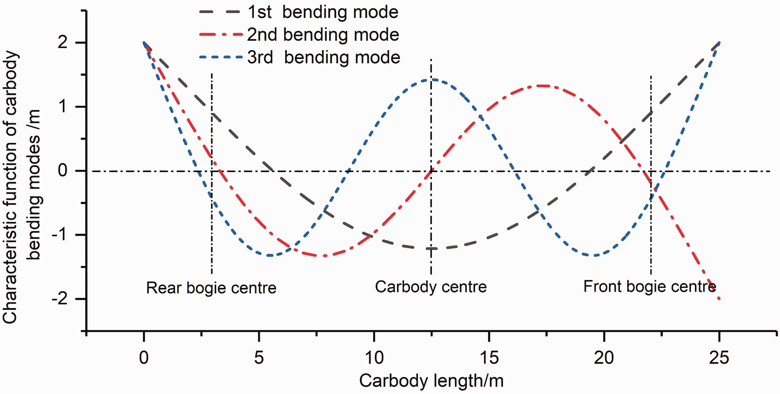
Modal shapes of the first three car-body bending modes.
The equations governing the variation in time of the coordinates 
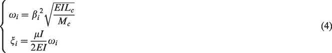
According to the above equations, natural frequencies for three bending modes are derived at 9.0 Hz, 24.7 Hz and 48.5 Hz. It should be noted that as far as ride comfort is concerned, the 2nd and 3rd bending modes are far less important than the first bending mode since harmonic components of car body vibration falling in the frequency range above 20 Hz have a minor influence on ride comfort.4,17 Nevertheless, the 2nd and 3rd bending modes are also considered in the simplified model, to consider the effect of high-frequency vibration of the car body which might have an impact on the performance of the active or semi-active suspensions.
The equations governing the variation in time of the 6 coordinates describing the rigid motion of the car-body and bogies are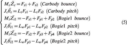
The car-body acceleration is derived from the superposition of car-body rigid modes and bending modes. Particularly important in view of the definition of the regulators, are the accelerations of the car-body over the front and rear bogies and at car-body centre, 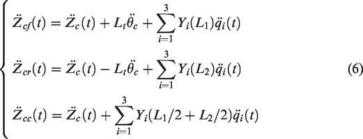
The forces from the secondary suspension and primary suspension are computed according to equation (7), in which 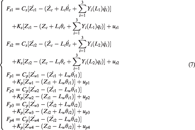
For the control forces 
When the semi-active suspension is implemented, the reference force 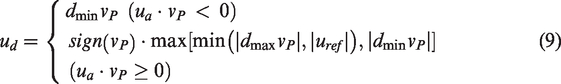
In equation (9) the minimum and maximum damping values
Flexible multibody system model
In addition to the simplified model, an FMBS model of the same vehicle is built in SIMPACK to provide a more detailed description of vehicle dynamics (see Figure 3). The model considers one car-body, two bogies and four wheelsets, with each body having six degrees of freedom, and eight axle-boxes, rotating with respect to the wheelset axis. A finite element car-body model is integrated to reflect the real car-body flexible modes, considering the first 28 flexible vibration modes of the car-body, which allows reproducing car-body dynamics in the frequency range up to 30 Hz. Besides extending the simplified two-dimensional (2-D) model to three-dimensional (3-D) model, the FMBS model takes into account some detailed arrangement for primary suspension that cannot be reproduced in the simplified model. In vertical direction, a coil spring on the top of the axle-box bears the vertical load. At the outer side of the axle-box, a vertical damper is mounted, and at the inner side of the axle-box a traction rod connects the bogie side beam and the axle-box, providing the primary yaw stiffness. In the secondary suspension, each bogie has two vertical dampers, one lateral damper and one anti-roll bar. The traction link is also considered to transfer the longitudinal force between the bogies and the car-body. Hertz contact and FASTSIM are used to calculate normal and tangent force at wheel-rail interface. Measured track irregularities from a real track with low maintenance quality are considered, including longitudinal level, lateral alignment, cross level and gauge variation. The parameters of the FMBS model are summarized in Appendix 1.
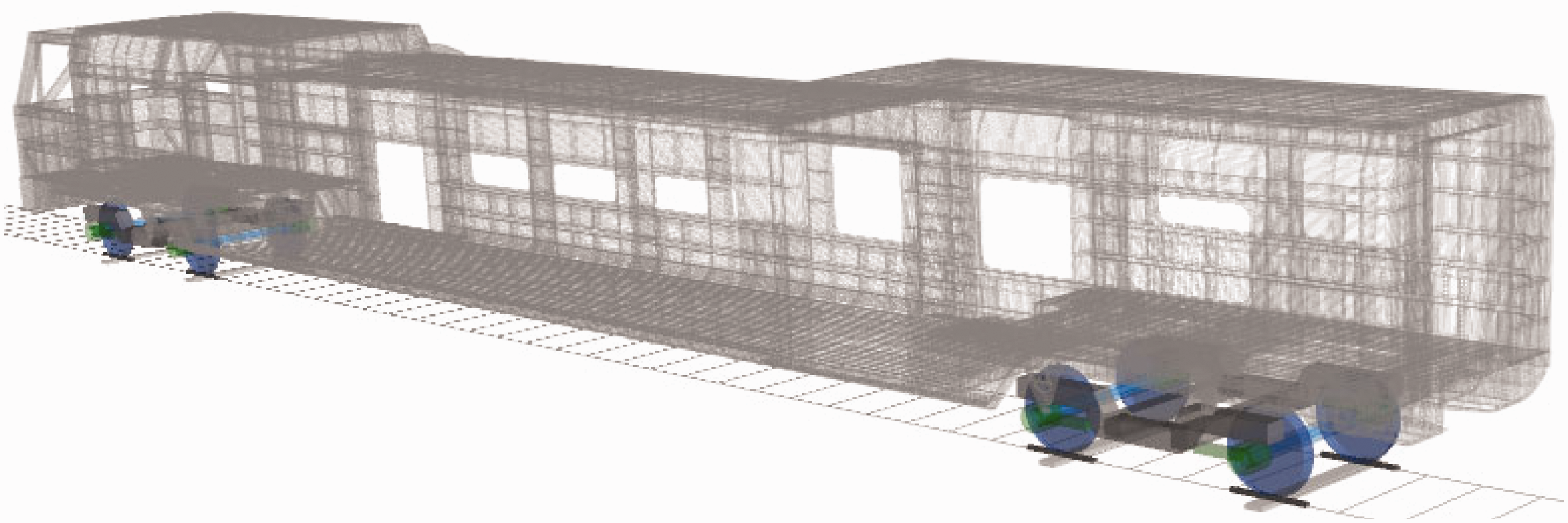
Full-scaled vehicle model.
Analysis of passive vehicle models
PSD of car-body acceleration from simplified model
The vertical accelerations of the car-body at front, centre and rear positions are evaluated according to equation (6) and the corresponding power spectral density (PSD) curves are shown in Figure 4. The PSD curves are processed using Periodogram method using a Hanning window with a setting of 5-second window length and 0.5 overlap rate.
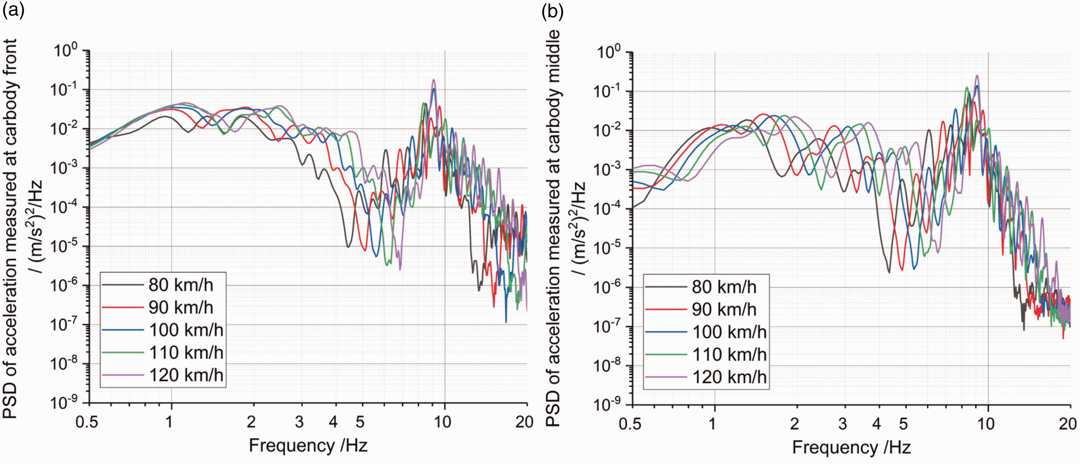
PSDs of vertical car-body acceleration from the 9-DOF model: (a) car-body front; (b) car-body centre.
As shown in Figure 4, the low-frequency car-body rigid vibrations and car-body first bending mode at 9 Hz are mostly excited by track irregularities, and the maximum peak value of the PSD at 9 Hz is affected by vehicle speed and takes a maximum value for vehicle speed 120 km/h. The car-body pitch motion resonates at approximately 0.9 Hz and affects mainly the acceleration at car-body front (above bogie centre), whereas the first bending mode causes more intensive vibration at car-body centre, consistently with its modal shape shown in Figure 2. The vehicle vibration at speed of 120 km/h is used as the reference for further analyses.
Comparison between simplified model and full-scaled vehicle model
In this section, the results obtained from the 9-DOF and the FMBS models of the vehicle in passive configuration are compared in terms of the PSDs of car-body acceleration at 120 km/h (see Figure 5). On one hand, the differences show the influence of dynamic effects not considered in the simplified model: the FMBS model includes a larger number of flexible modes for the car-body, resulting in more intense dynamics above 15 Hz compared to the simplified model. However, in the frequency range below 15 Hz, a quite good agreement between the two models is observed, justifying the use of the simplified model for the design of model-based controllers (see the upcoming section) and also to perform an initial exploratory analysis of the benefits of semi-active and active suspension control.
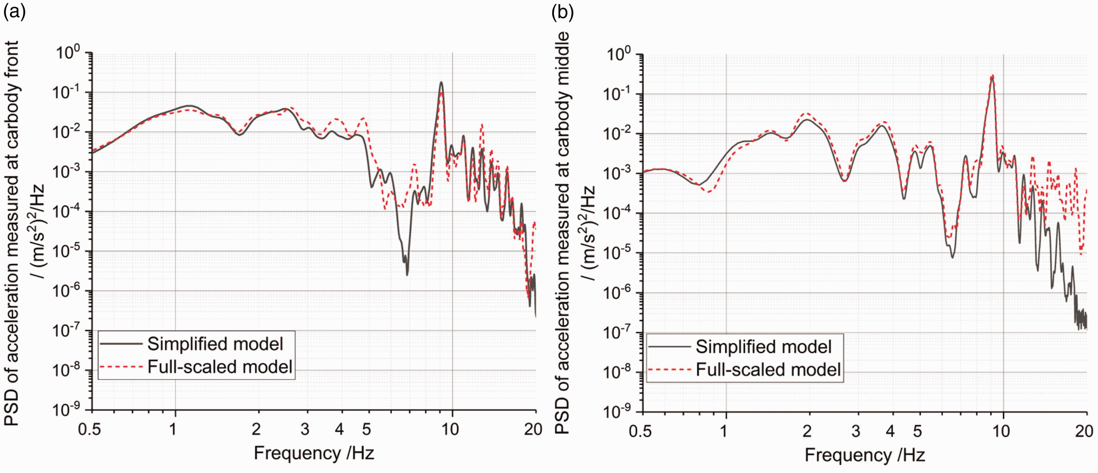
Comparison of PSDs of vertical acceleration at 120 km/h for the 9-DOF and FMBS models at (a) car-body front and (b) car-body centre positions.
Control strategies for active suspensions
Two model-based control strategies, namely LQG and H∞, are considered in this work as they allow a similar implementation for both full-active and semi-active control in secondary and primary suspensions, allowing an objective comparison of the alternative approaches to improving ride quality.
LQG control
The LQG controller consists of the integration of the Linear Quadratic Regulator (LQR) and state estimation based on the Kalman filter.20,21 In LQR, a linear feedback of the system’s full state is applied, with the objective of minimising a linear quadratic cost function J which involves a measure of the system’s performance to be improved and a measure of the control force/effort to be reduced. Assuming the observation of the full state of the system is not feasible or practical, a Kalman filter is used to estimate the system’s state variables based on a reduced set of measurements. The schematic diagram of LQG control is shown in Figure 6.
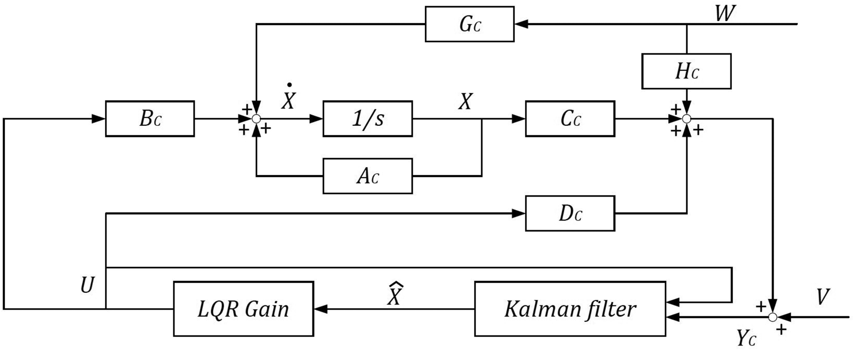
Schematic diagram of LQG control.
The state-space equations of the vehicle model are derived in form of equation (10) according to the equations of the 9-DOF model introduced in the section “Simplified 9-DOF vehicle model”


The cost function of LQR is defined as

A feedback control gain 
As far as state estimation is concerned, it is observed that in the 9-DOF model the pitch motion of the two bogies are not affecting car-body vibration and therefore the state variables associated with bogie pitch motions have no contribution to the control force. In other words, we don’t need to observe the full-state vehicle system but a sub-system with removal of bogie pitch motions.
A 5-sensor measuring set-up is proposed for the Kalman filter, using three accelerometers mounted on the car-body at the same positions considered in the definition of the control target 
control
Although the LQG controller can provide an excellent performance in ideal condition, it might be bothered with robustness issue, in case the stability margins are reduced by the effect of uncertainties in the vehicle model, such as fluctuations of the car-body mass or deviation of suspension parameters from their nominal values.
22
Robustness to modelling errors and parameter uncertainties must however be guaranteed in a real application and
The principle of H∞ control is illustrated in Figure 7, where the original open-loop system is expressed as 
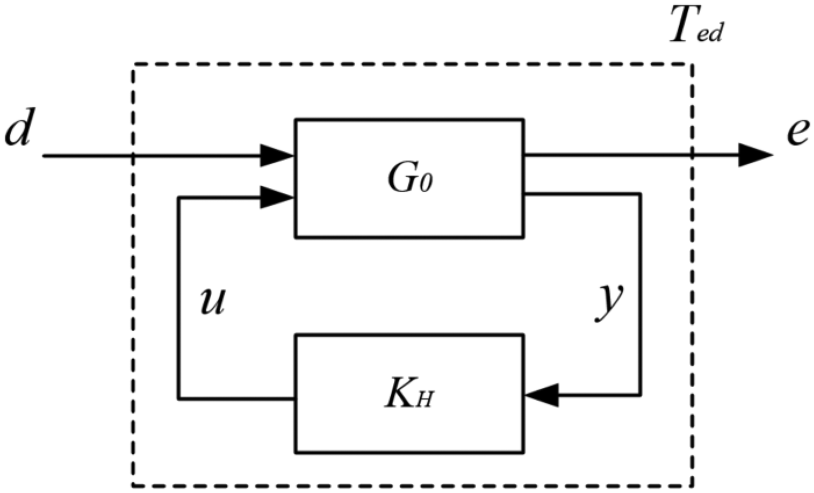
Control principle of H∞ control.
The implementation of the H∞ control for the mitigation of car-body vibration being the objective of this study is shown in Figure 8 for the case of active or semi-active secondary suspensions. The schematic diagram of the H∞ control is slightly different for the case of active or semi-active primary suspensions, due to the need to consider a double number of control forces.
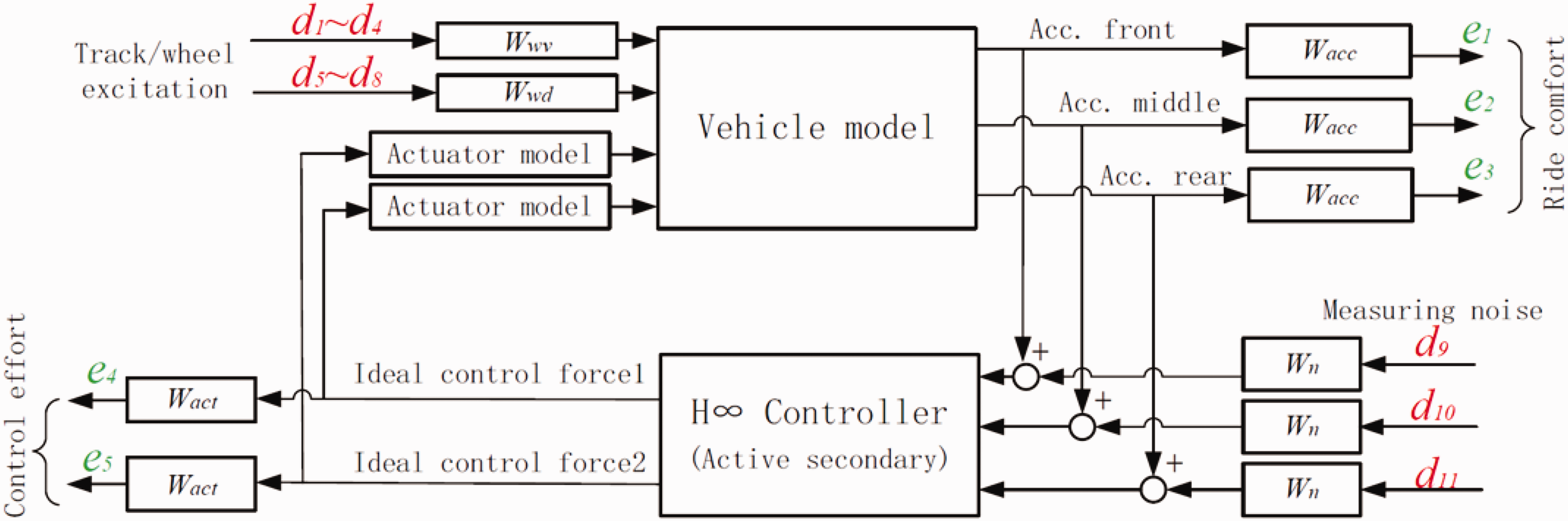
Arrangement of H∞ control for active or semi-active secondary suspensions.
The error vector e considers: the weighted accelerations of the car-body over the front bogie, at car-body centre and over the rear bogie (components the weighted control efforts generated by the actuators or semi-active dampers (components
The disturbance vector includes the components of wheel vertical velocities
In the implementation of H∞ control proposed here, the actuator model is expressed as a first-order filter considering the response time of the actuator, see equation (8). The weighting functions
Frequency-dependent weight functions are introduced for each term in the error and disturbance vectors. The weight function
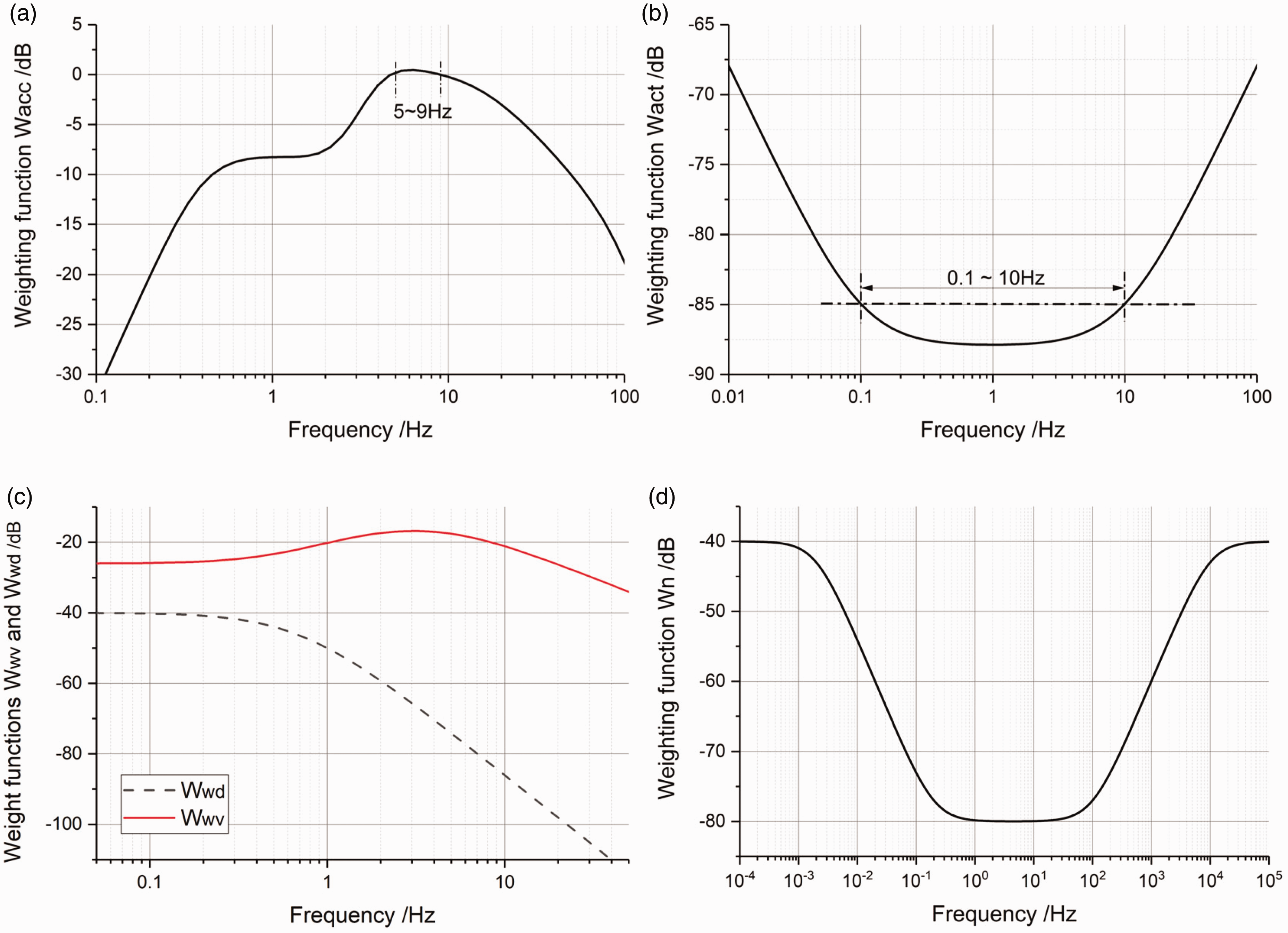
Curves for weight functions: (a) weight function
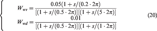
Regarding the transfer functions weighting the disturbance from track irregularities
It is worth noting that a different choice of the frequency-dependent weighting functions would result in a different design of the H∞ controller. For instance, tuning of the weight functions can be used to shift the control effort towards a more effective mitigation of high-frequency structural vibrations at the expense of low-frequency vibration related to the rigid modes of the vehicle or vice-versa. The optimisation of the design of the H∞ controller is however beyond the scope of this work, whilst it is important to underline that the same weight functions were used for the four mechatronic suspension schemes considered (full-active/semi-active secondary and full-active/semi-active primary) to ensure an objective comparison.

Results of simplified model
In this section, the simplified vehicle model is used to investigate the benefits of using semi-active or full-active control in the primary and secondary suspensions. Depending on the case considered (full-active primary, semi-active primary, full active secondary, semi-active secondary) some of the passive dampers in the 9-DOF model shown in Figure 1 are replaced by actuators or semi-active dampers. In all cases, a small amount of passive damping is maintained in the suspension where the active or semi-active component is introduced, to consider the minor damping effects due to the passive air spring in the secondary suspension and from primary springs. The residual passive damping considered is 10 kNs/m per bogie for the secondary suspension and 1 kNs/m per wheelset for the primary suspension.
All results presented in this section refer to the vehicle speed of 120 km/h and, unless differently specified, the response time of the actuators and semi-active dampers is set to 10 ms.
Results with LQG controller
For the case of active/semi-active secondary suspensions, the weight matrixes 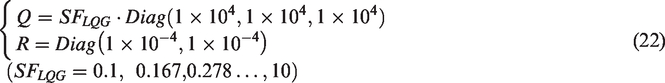
A scaling factor SFLQG is applied to the
For the case of active/semi-active primary suspension, the
Figure 10(a) and (b) present the PSDs of car-body accelerations measured at car-body centre and over the front bogie, considering the four active/semi-active suspension options. The results are arranged in a four-quadrant in order to facilitate the comparison of the four options.
PSDs of acceleration under four suspension technologies: (a) PSDs of car-body vertical acceleration at car-body centre; (b) PSDs of car-body vertical acceleration of the car-body over the front bogie.
As shown in the right-top corner of Figure 10(a) and (b), full-active secondary suspension can effectively reduce the vibration at all frequencies even using a small value of the scaling factor SFLQG. By contrast, the result obtained for the semi-active secondary suspension, in the left-top corner of the figures, is less effective than the full-active suspension, especially in respect of the rigid modes of the car-body but is still capable of attenuating the peak in the PSD related to the first bending mode of the car-body by more than a factor 10. The use of a relatively large scaling factor is required to avoid an increase of vibration in the frequency range around 1 Hz which is related to the rigid modes of vibration of the car-body and is more clearly seen over the front bogie. The reason for the relatively bad performance of the semi-active secondary suspension in the frequency range around 1 Hz is that in this frequency range the rate of damper elongation/compression is low and therefore a much lower control force can be produced by the semi-active device compared to a full-active component.
Full-active primary suspension is presented in the right-bottom corner of Figure 10 and can reduce substantially car-body vibration in the frequency range from 5 Hz to 15 Hz but requires large values of the scaling factor SFLQG. Car-body vibrations in the low-frequency range are also improved to some extent, at the expense of a large scaling factor, hence large actuator forces. Finally, semi-active primary suspension, shown in the left-bottom corner of the figures, provides a negligible improvement in the low-frequency range but is capable of attenuating very effectively vibration components related to car-body bending, reducing the peak of the PSD at 9 Hz by a factor above 10, provided a sufficiently large scaling factor is used. This remarkable performance is due to the fact that controlled primary suspensions can effectively mitigate bogie vibration in the high-frequency range thanks to the large rate of elongation/compression primary dampers in the 5-15 Hz frequency range, thereby cutting drastically the amount of high-frequency vibration transmitted to the car-body.
In conclusion, as expected the active secondary suspension provides the largest benefit in terms of reducing car-body vibration in the entire frequency range of interest. Active primary suspension requires a larger control effort and can only improve the ride quality in the high-frequency range, so this is certainly a less attractive solution, even not considering implementation issues such as the need to fit active actuators in the narrow installation space of primary suspension and reliability issues due to the exposure of actuators to large vibrations. Semi-active primary suspension appears as an interesting option, as it provides significant attenuation of car-body vibration in the high-frequency range, but its advantage in the low-frequency range related to the rigid modes of the car-body is limited. From a practical point of view, it may be difficult to fit semi-active dampers having the required maximum damping in the secondary suspension, considering that many modern passenger vehicles are not including vertical dampers in the secondary suspension and instead are using orifice damping in the air spring to provide vertical secondary damping. Finally, semi-active primary suspension also provides a very effective reduction of vibration related to the car-body bending modes and at the same time benefits from a relatively simple implementation, as the passive primary dampers are replaced by controllable dampers that may have a similar size thereby easily fitting in the available installation space. Another advantage of semi-active primary suspension over mechatronic secondary suspensions is that the vibration of the bogie frame can also be reduced, reducing dynamic stresses in the frame itself and other components installed in the bogie, e.g. brake callipers.
Simulation results with
controller and comparison with LQG controller
Similar to the study of LQG control in the previous section, a scaling factor SFHinf is also introduced for
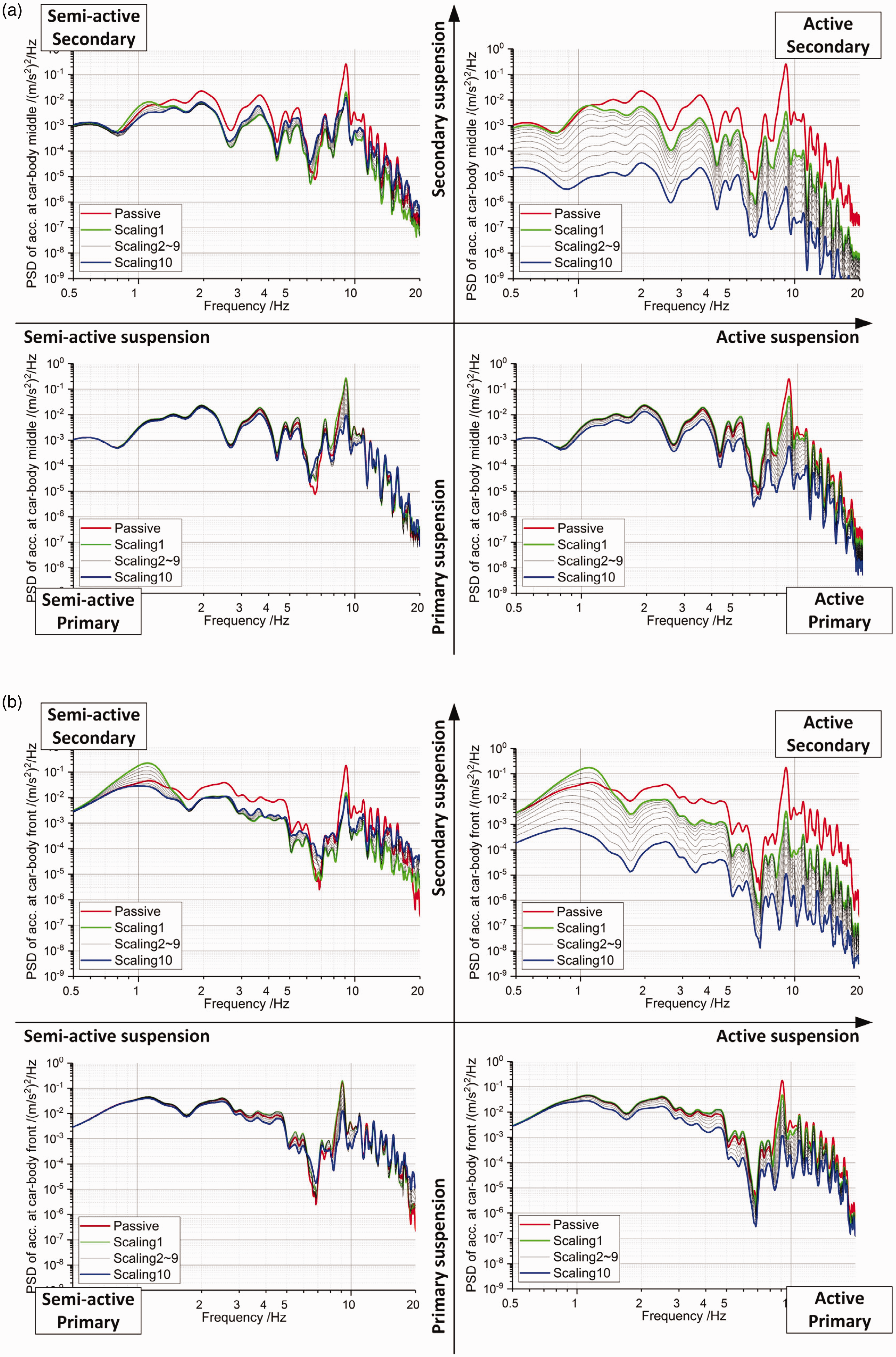
The performance of the four active/semi-active options with H∞ controller is compared in Figure 11 in terms of the PSDs of acceleration at car-body front, using the same representation as Figure 10 for the LQG controller. In the case of full-active secondary suspension, the H∞ controller is slightly less effective than the LQG controller with reducing the vibration of the car-body in the low-frequency range, but at the same time, H∞ has slightly a better performance than LQG in the high-frequency range. This difference comes from the fact that the weight function defined for the H∞ favours a more focused effort of the control force in the frequency range 5-9 Hz, which is according to ISO 2631 most relevant to vertical ride comfort.
PSDs of car-body vertical acceleration over front bogie under four suspension technologies.
The frequency-weighted effect of the H∞ controller also affects the performance of the semi-active secondary suspension, see the left-top corner of Figure 11. Car-body vibrations in the 2∼10 Hz frequency range are effectively reduced, but the PSDs at frequencies around 1 Hz are higher compared to the passive vehicle, even for large values of the SFHinf scaling factor. One solution to this issue could be to use a different weight function Wacc in H∞ controller so that more emphasis is placed by the controller on reducing vibrations in the low-frequency range, although this could somehow reduce the effectiveness of the controller at higher frequencies. Therefore, a proper design for semi-active secondary suspension needs to find a balance between controlling low-frequency and high-frequency vibrations of the car-body.
Finally, for full-active and semi-active primary suspensions the differences between the PSD curves obtained using the H∞ and LQG controllers are minor.
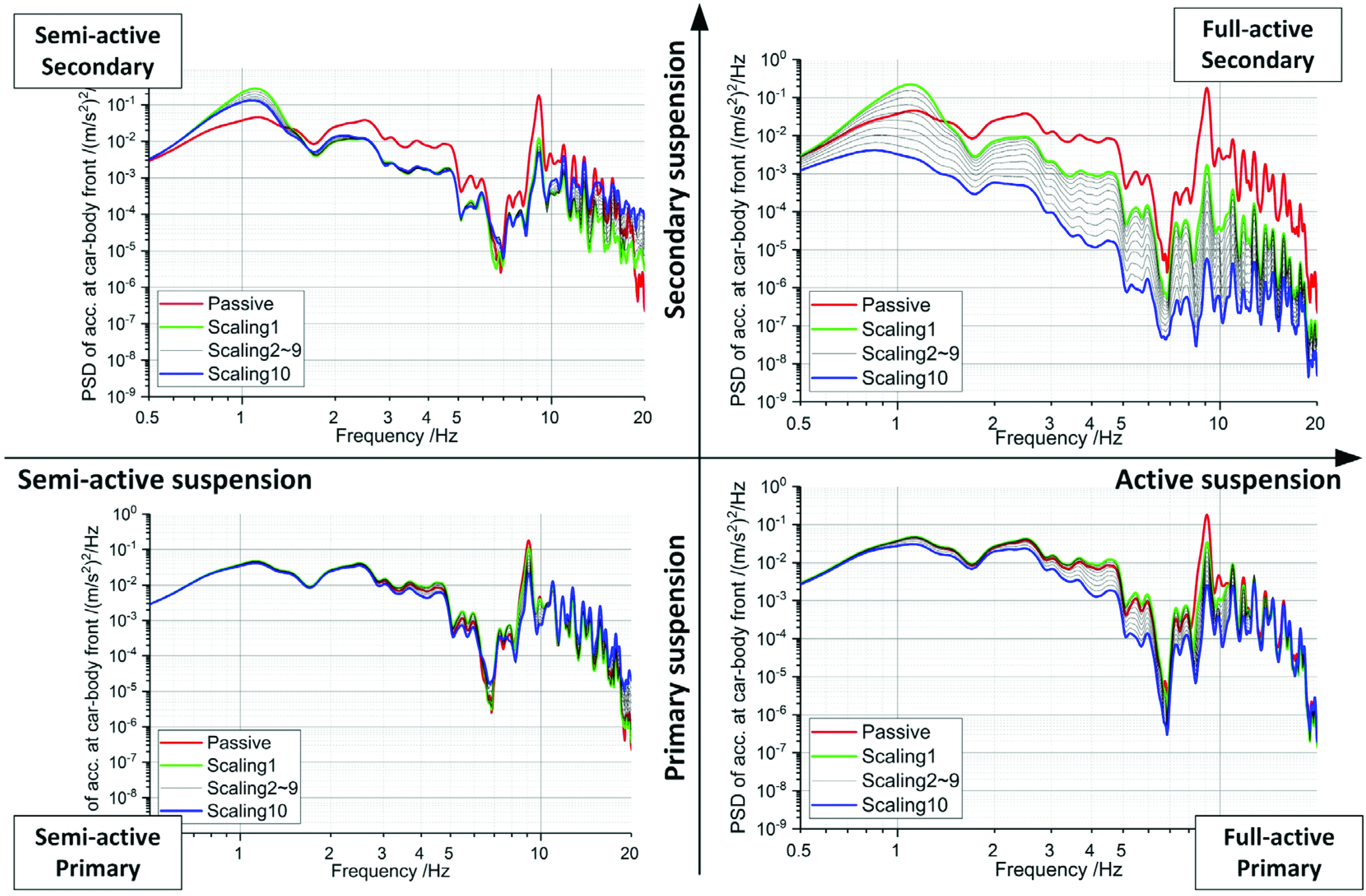
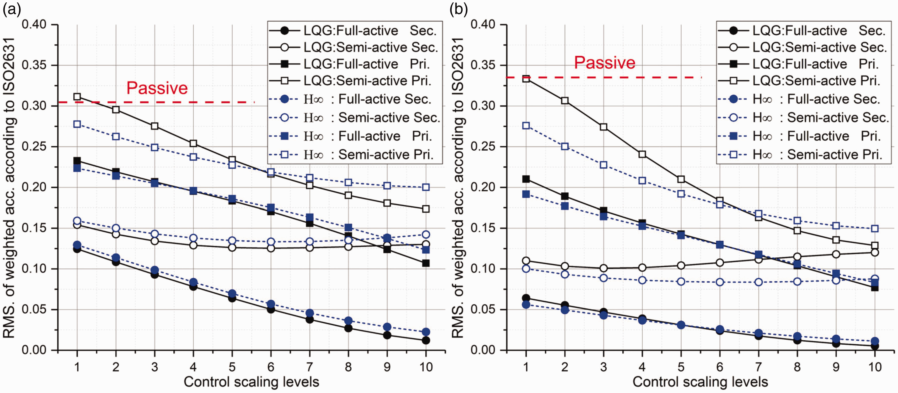
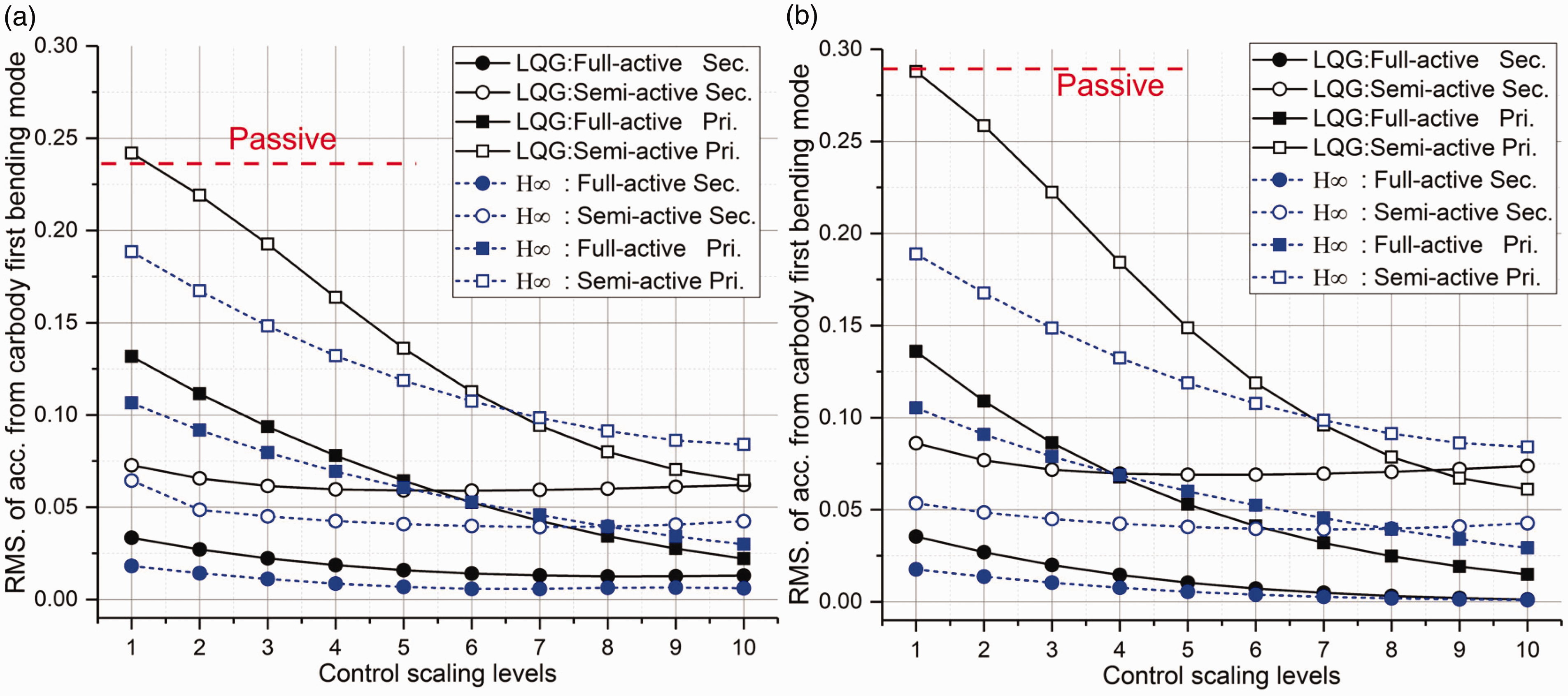
To provide a more comprehensive comparison of the performance of the LQG and H∞ controllers, the RMS values of frequency-weighted acceleration according to ISO 2631 at vehicle speed 120 km/h are compared in Figure 12 for the four active/semi-active suspension options and for different values of the scaling factors SFLQG/SFHinf. Figure 12(a) shows the results for the car-body point over the front bogie and Figure 12(b) for the centre of the car-body. The corresponding RMS values for the passive vehicle are shown in each plot by a horizontal dashed line with no markers.
Comparison of RMS of car-body vertical acceleration with LQG controller and
As expected, the best performances are reached by full-active secondary suspension, providing a substantial reduction of car-body vibration compared to the passive case even for low values of the scaling factor. Considering SFLQG/SFHinf at level 1, the reduction of the RMS acceleration compared to the passive case is by a factor nearly 3 over the front bogie and by a factor 6 or more for the centre of the car-body. The better effect of active control in the car-body centre is due to the fact that at this point the vibration of the car-body is more heavily affected by the resonance of the first bending mode. A further increase of the scaling factors provides a further reduction of the RMS, which, however, is probably not needed as the ride quality would be already very good for the relatively low levels of the scaling factor. Semi-active secondary suspension also shows a remarkable reduction of car-body vibration at both locations considered, but the improvement resulting from an increase of the scaling factors is limited. For the full-active primary suspension, the RMS acceleration at both locations decreases steadily with increasing levels of the scaling factors and becomes even lower than the semi-active secondary suspension when large scaling coefficients are applied. Finally, semi-active primary suspension, although providing the least reduction of the weighted RMS acceleration among the four options considered, can still reduce by a factor above 2 the vibrations at car-body centre compared to the passive vehicle, provided a sufficiently large scaling factor is used.
For the two full-active options, the performance obtained using the LQG and H∞ controllers are very similar, but for semi-active secondary suspension the use of the LQG controller leads to a more effective attenuation of car-body vibration over the front bogie, compared to H∞, but at car-body centre the opposite situation is found, and a better performance is provided by the H∞ controller. This is due to the fact that
To focus on the suppression of car-body structural vibration related to the first bending mode, we extract the acceleration coming from the car-body first bending mode at 9 Hz, using a band-pass filter with frequency range specified from 8.5 to 9.5 Hz (see Figure 13).
Comparison of RMS. of acceleration coming from car-body bending mode with LQG controller and
Semi-active primary suspension can reduce by 70–80% car-body first bending vibration if the largest scaling factor is chosen, either using LQG or
Finally, Figure 14 compares the peak magnitude of the control force in full-active primary and secondary suspensions as a function of the scaling factor level, for the LQG and H∞ controllers. When large scaling factors are used, active primary suspension requires a peak force close to 15 kN, which may lead to a complex and expensive design of actuators. It should be recalled that the performance of full-active primary suspension is highly depending on the intensity of the control action, see Figure 12, so this is another point advising against the use of full-active primary suspension. The difference between the peak force implied by the use of LQG or H∞ controllers is limited for both active primary and active secondary and for all the scaling factors considered. The control force mentioned above is obtained based on the simplified two-dimensional model, where each bogie has one actuator for secondary suspension and two actuators for primary suspension. However, for the real vehicle, the number of actuators would be doubled, due to the symmetrical arrangement at left and right sides, which means that control force will be achieved by two actuators and each actuator capable of producing 8 kN force is enough to realize the highest control level in Figure 14.
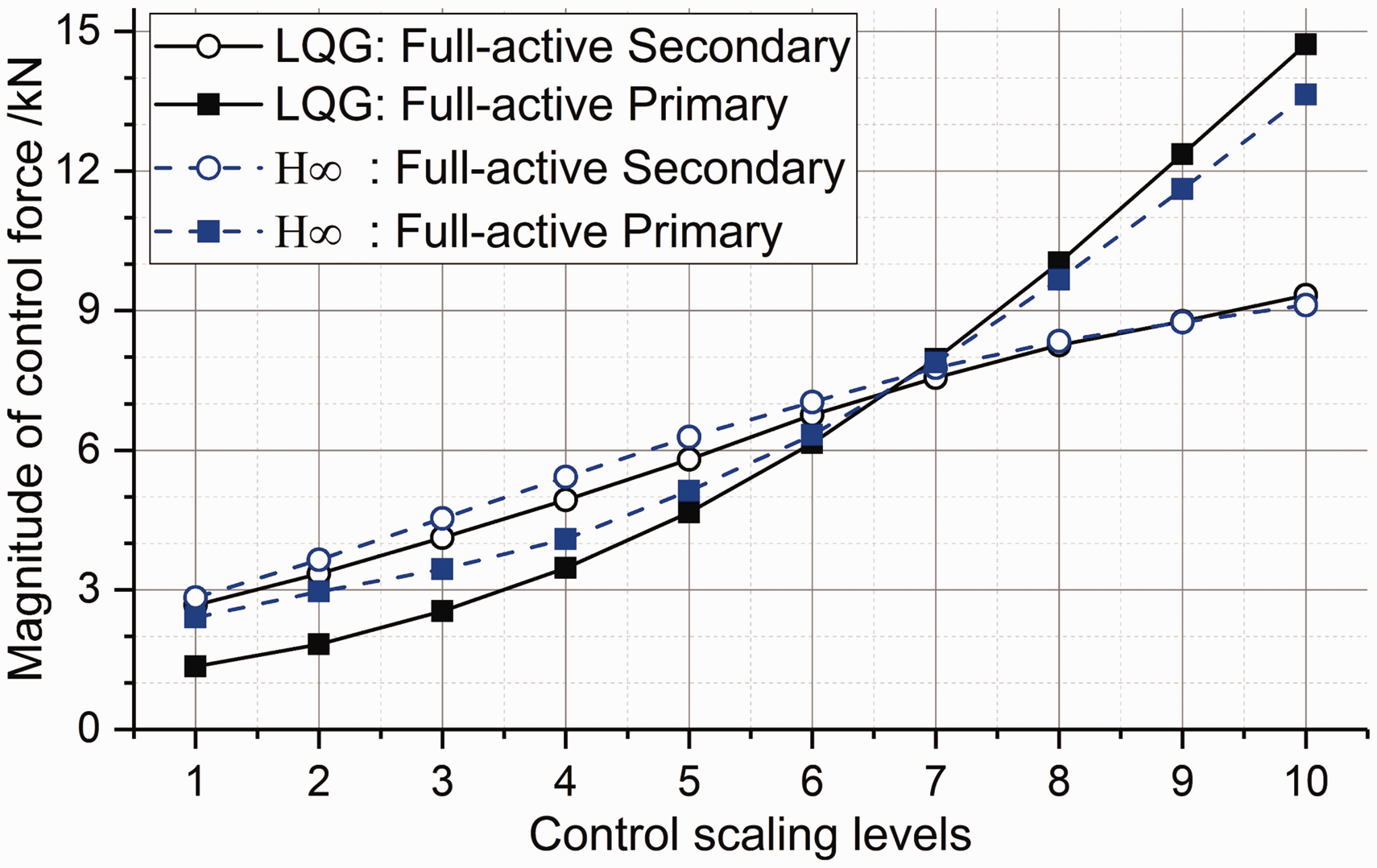
Comparison of control force with LQG controller and
It is also worth mentioning that in this paper a common sensor set-up considering the measure of car-body accelerations at three locations is used for all four mechatronic suspension schemes to enable an objective comparison among them. However, the real implementation of each mechatronic suspension scheme could be customized with different control targets, weight functions and sensor set-ups, according to the specific features of the technology adopted. One good example can be found in reference 6 where Sugahara used semi-active primary suspension to improve vertical ride comfort. Instead of using three car-body accelerations as the control target, the authors tried to separately control different vibration modes of the vehicle, including bounce and pitch motions of car-body and bogies and car-body first bending mode. This choice allows to put more emphasis on the mitigation of car-body bending modes rather than car-body rigid modes, focussing the use of semi-active primary suspension to a task that can be effectively performed by this suspension scheme.
Influence of response time of actuator/semi-active damper
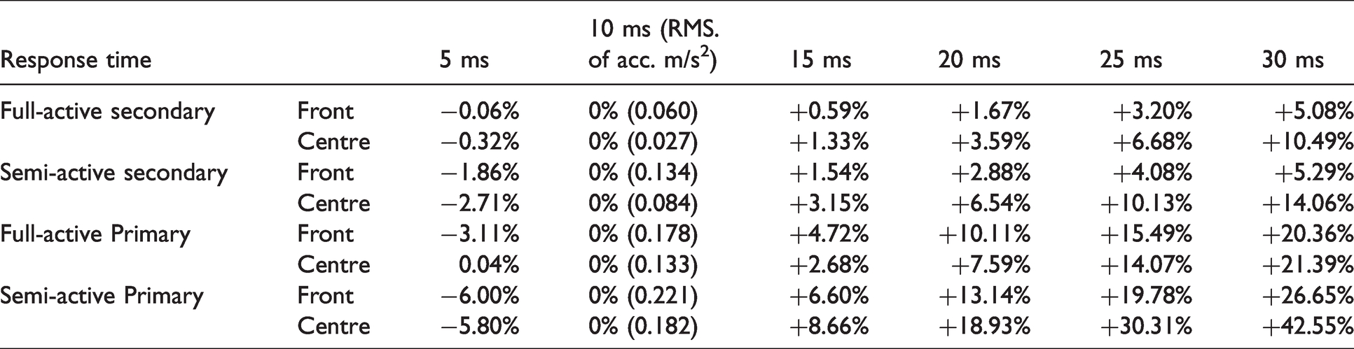
In the simulations above, the response time of the actuator and the semi-active damper is set to 10 ms using a first-order filter. This value might be achievable for fast semi-active dampers e.g. using a magneto-rheologic technology, but would be challenging for a full-active actuator, depending on the technologies considered. 27 In this section, the influence of the response time is studied. Using H∞ control and a value SFHinf =1 of the scaling factor (approximately corresponding to scaling factor level 6 of SFHinf in the analysis presented in the previous section), simulations are repeated considering different values of the response time increasing from 5 ms to 30 ms.
The results of this analysis are summarized in Table 2, where the weighted RMS of acceleration with the response time at 10 ms is used as a reference to show the reduction and increase of RMS with faster and slower response times. Mechatronic suspension schemes mainly concerned with the reduction of high-frequency vibration components are more sensitive to the time response of actuators or adjustable dampers. In particular, for semi-active primary suspension the degradation of ride quality at car-body centre becomes very large (above 30%) if the response time is larger than 20 ms. Performance degradation is less critical for secondary suspensions, either full-active or semi-active, as vibration attenuation in the low-frequency range is affected to a lesser extent. The results obtained for the LQG controller are comparable and are not presented for the sake of brevity.
Influence of response time of actuator/semi-active damper.
Key parameters of full-scaled SIMPACK model.
Simulations based on full-scaled vehicle
The theory study based on the simplified 2-D model reveals the features of different technologies and shows significant improvement of ride quality using active or semi-active suspensions, but the working situation in the real case would be different as the 2-D model cannot accurately predict the real behaviours of the vehicle and excessive deviation between the real vehicle and the simplified model used in the design of the controller may lead to unsatisfactory performance. In this section, we explore the application of proposed control methods based on the simulation of a Flexible Multi-Body System (FMBS) vehicle model.
Co-simulation between SIMPACK and SIMULINK is implemented, where FMBS model built in SIMPACK exports the three car-body accelerations and damper velocities (only for semi-active control) to SIMULINK in which the controller receives the car-body acceleration and computes the control forces. These reference forces are fed to the simplified actuator/damper models, and the control forces are fed back to the FMBS model.
The H∞ controller developed in an earlier section is adopted as it shows better robustness than the LQG controller, capable of dealing with model uncertainties and disturbance, which makes it a practical solution for real application. The configuration of the H∞ controller is the same as is introduced in an earlier section for four suspension technologies. In the FMBS model, two actuators/controlled dampers are considered for each wheelset in mechatronic primary suspension, or for each bogie in the secondary suspension and the same reference force is defined for the two sides. The car-body roll motion has limited contribution to the vertical vibration, so the accelerometer sensors used by the H∞ controller are assumed to be installed along the centreline of the car-body. When (semi) active suspension technology is applied, the corresponding passive dampers are removed from the FMBS model but a small amount of passive damping is maintained in the suspension in the same way as done for the 9-DOF model. The response time of actuators and damper is set to 10 ms.
Figure 15 shows the time histories of acceleration at car-body centre for the vehicle running at 120 km/h and scaling factor SFHinf =1 in H∞ control. The results show a significant reduction of car-body acceleration for all schemes, with full-active secondary suspension providing the best performance, as expected.
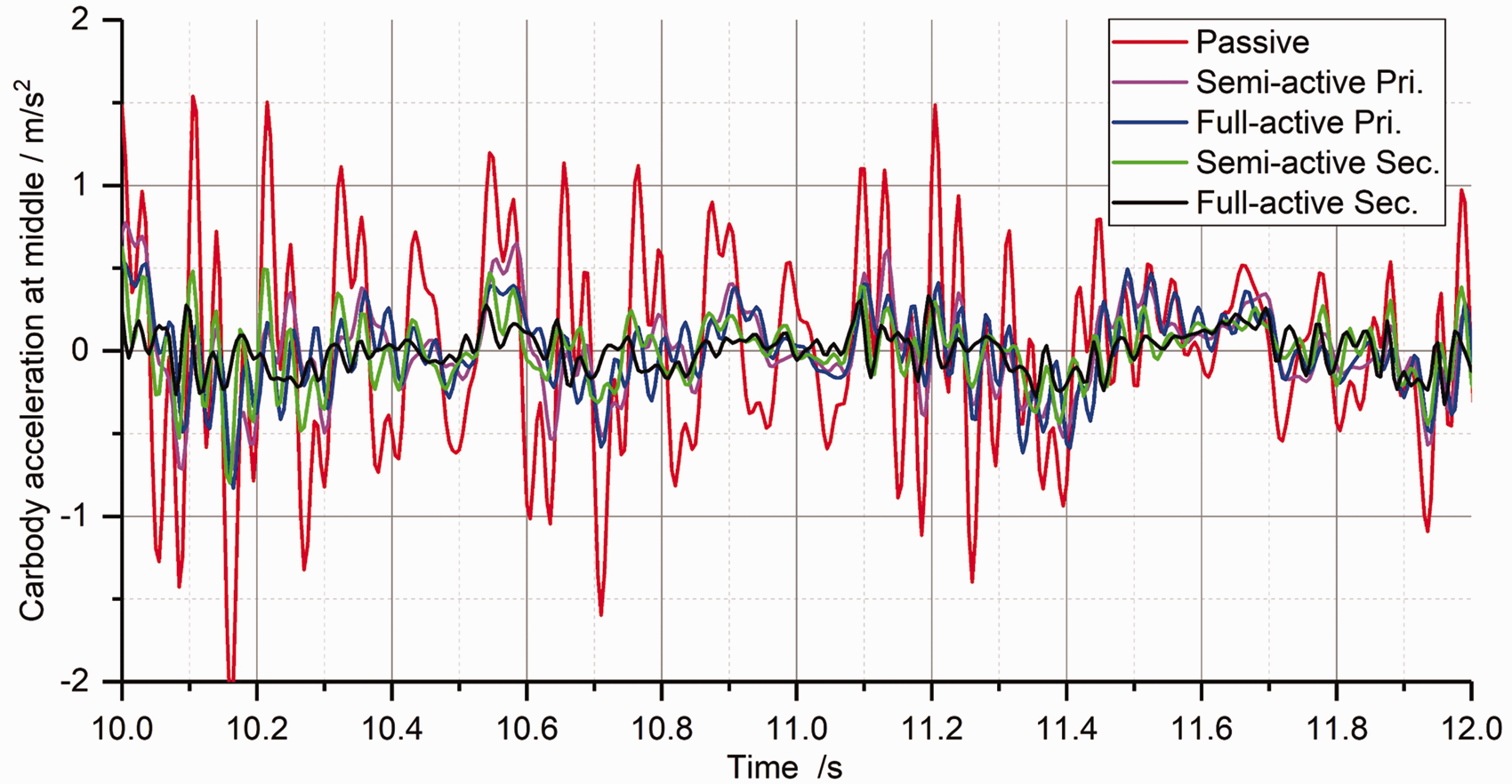
Time history of car-body vertical acceleration at centre position with different technologies.
The PSDs of car-body accelerations over the front bogie and at car-body centre are presented in Figure 16. These results confirm the conclusions obtained from the simplified 9-DOF model: the full-active secondary suspension effectively reduces car-body vibration in the entire frequency range of interest at both positions. The semi-active secondary suspension also mitigates car-body vibration in a wide frequency range but does not provide a benefit or even slightly increases the vibration at frequencies around 1 Hz. Furthermore, the reduction of the PSD peak at 9 Hz is less pronounced for semi-active secondary suspension compared to full-active secondary suspension. Semi-active primary suspension effectively mitigates vibration at 9 Hz related to the first bending mode without negatively affecting ride comfort at lower frequencies. Full-active primary scheme shows further improvement at this resonance frequency and a broader frequency range of improved vibrations nearly from 7 to 10 Hz.
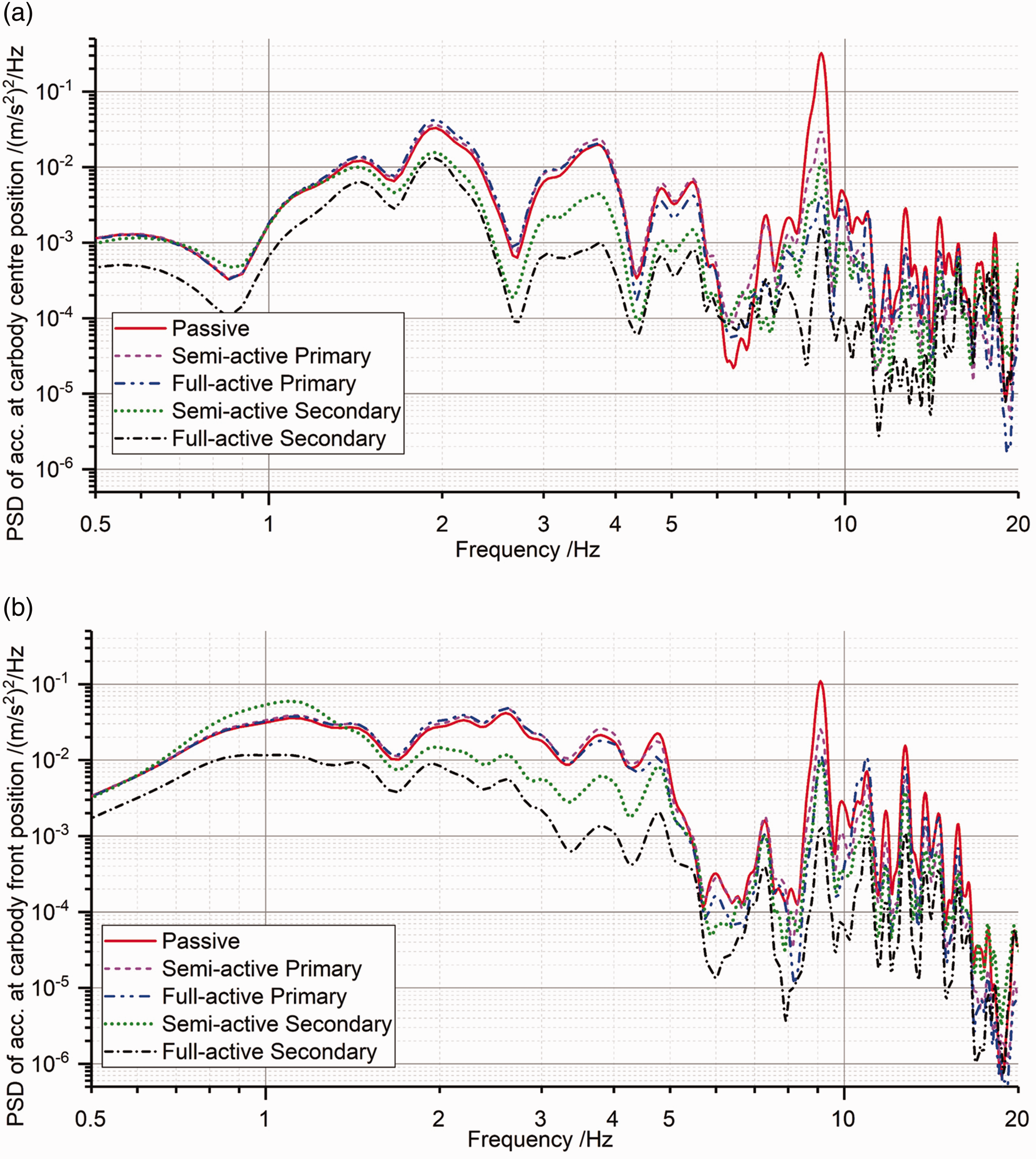
Performance of the four (semi) active suspension technologies at speed 120 km/h: (a) PSD of car-body vertical acceleration at centre position; (b) PSD of car-body vertical acceleration at front position.
The time histories of control force for active primary and active secondary suspensions are presented in Figure 17, from which we can see that the maximum magnitude of control force for active secondary and primary suspension is 5 kN and 4 kN respectively, close to one half the magnitude of the force in Figure 14 for control level 6 (the nearest level to “SFHinf =1”) and small enough to be realized by real actuators.
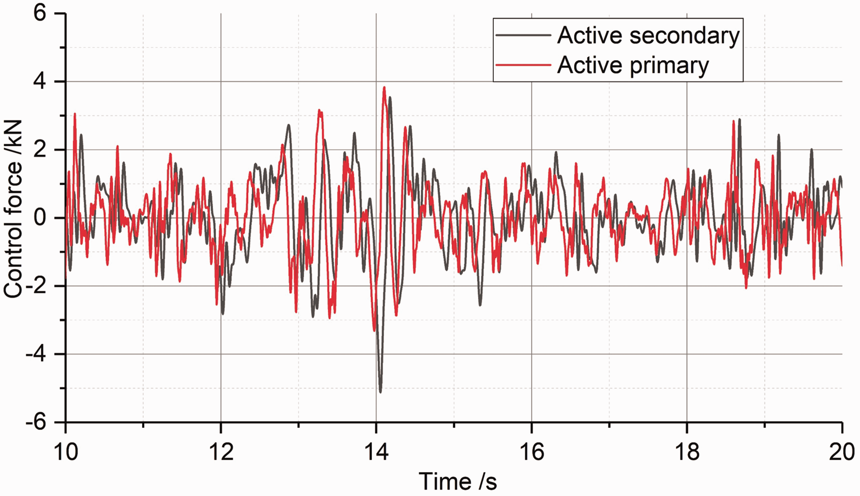
Time history of control force of active secondary and primary suspension.
Figure 18 shows the trend with the speed of the RMS of car-body accelerations weighted by the filter in ISO 2631. For the passive vehicle, the results of the FMBS are in good agreement with those of the simplified 9-DOF model over the front bogie at 120 km/h, the weighted RMS being 0.31 m/s2 and 0.30 m/s2 for the two models, but in the body centre the FMBS provides a larger value of the weighted RMS, 0.44 m/s2 compared to 0.33 m/s2 for the simplified model, due to the more detailed representation of car-body structural vibrations. The relatively simple semi-active primary suspension provides a reduction of the weighted RMS acceleration at car-body centre up to -44% at 120 km/h. This is less than the reduction predicted by the simplified model (see Figure 12(b)), but is still very significant. The reduction of car-body vibration over the front bogie is less pronounced since the vibration of this point is less heavily affected by the bending modes. The benefit of full-active primary suspension compared to semi-active primary suspension is limited, whereas the results of the 9-DOF model show significant benefit of full-active primary vs. semi-active primary suspensions. This is due to the fact that the simplified model does not consider some details of the secondary suspensions (particularly the traction links) introducing a coupling between car-body bending and bogie pitch motion. 28 This topic is identified as the subject for a future extension of this work. Full-active and semi-active secondary suspensions are the best and second-best solutions, showing good improvement at all speed levels, providing approximately 70% and 50% reduction of frequency-weighted accelerations at both centre position and front position at 120 km/h. However, there is no practical scope with going too far in the mitigation of car-body vibration, so probably a semi-active primary or secondary suspension can provide the required performance in regard of ride quality without the need to resort to the use of a more complex full-active secondary suspension.
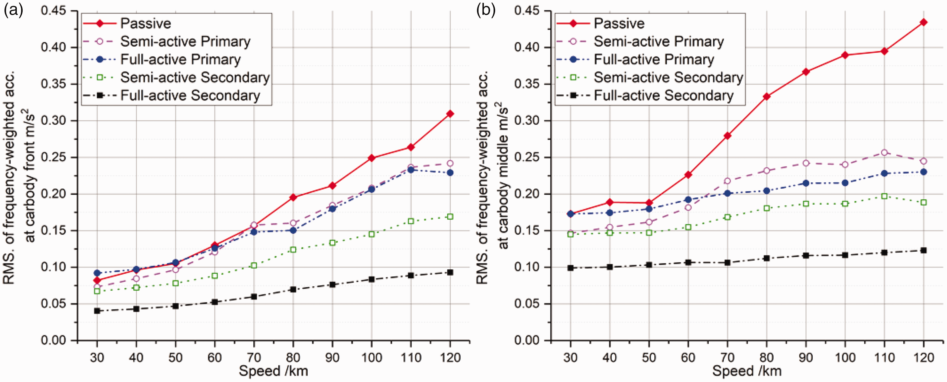
the improvement of vertical ride comfort at different speed levels: (a) car-body front position; (b) car-body centre position.
Discussion and conclusions
In this paper, an objective comparison of the benefits of four configurations for mechatronic suspensions in railway vehicles: full-active primary, semi-active primary, full-active secondary and semi-active secondary suspensions, is investigated. The study is performed using two levels of detail in modelling the railway vehicle: a simplified 9-DOF model using Euler beam to represent the car-body bending modes and an FMBS model in which the flexible car-body is modelled based on the modal synthesis, with the modal parameters coming from a detailed finite element model of the car-body. The comparison of results from the two models shows a generally good agreement. Therefore, it is concluded that the simple and computationally effective 9-DOF model can be used to perform extensive sensitivity analyses and can also be used in the design of model-based control strategies for the mechatronic suspensions. However, the FMBS provides a better insight into the performance of the different mechatronic suspension options as far as the mitigation of car-body structural vibrations is concerned.
LQG and H∞ controllers are considered in the study of the four mechatronic suspension schemes. The design of the controllers is performed in a consistent way for each scheme, to enable an objective comparative assessment of the four options.
Among the four configurations considered, full-active secondary suspension shows the best performance and provides excellent attenuation of low-frequency vibration related to the rigid modes of the car-body and, at the same time, of structural vibrations in a higher frequency range. Semi-active secondary suspension also provides a good performance and could be preferred to full-active suspensions due to their lower cost and ease of implementation. Semi-active primary suspension, although not suitable to mitigate low-frequency vibrations, provides a remarkable improvement of ride comfort in relation to the bending modes of the car-body. However, the good dynamic performance of the adjustable primary dampers is required, and the degradation of their performance is expected in case the response time is higher than 20 ms. Finally, full-active primary suspension provides limited advantage compared to semi-active primary suspension but involves a higher complexity and requires large actuation forces. Apart from active primary suspension, all the other three schemes show high potential for future implementation. Full-active secondary suspension provides the best performance in terms of mitigating car body vibrations, but might not be the preferred solution depending on the extent to which a simpler arrangement of the suspension can be traded for reduced performance. Moreover, the safety and reliability of the actuation system are highly relevant to the selection and design of mechatronic suspensions. 29
An objective comparison of the suspension schemes from the perspective of ride comfort improvement needs a common set-up of controllers and sensors, as can been seen that minimizing car-body accelerations at three locations is used for all four mechatronic suspension schemes in the controller in this paper. However, it is worth recalling that the final implementation of a mechatronic suspension scheme should also consider other factors not addressed in this paper such as suspension deflection, weight functions and sensor set-up.
It should be noted that in this study the coupling of car-body bending with the pitch and longitudinal vibration of the bogies is neglected by the 9-DOF model due to the effect of the traction links and yaw dampers. 28 This effect is sufficiently weak for a low-speed vehicle like the one considered in this study, but for a high-speed vehicle equipped with yaw dampers, it may lead to unacceptable deviation of the simplified model from the actual dynamic behaviour of the vehicle, which would, in turn, cause the failure of control strategies designed using the simplified model described in this paper. The nonlinear behaviour of the semi-active damper is not considered in this work. An extension of this study is envisaged to upgrade the 9-DOF model considering the coupling effects produced by the traction links and yaw dampers, and to consider a more realistic model of a magneto-rheologic damper to be used in the primary suspensions, moving forward to the application of the methods described in this paper to a real case.
Footnotes
Acknowledgement
The authors thank the company Blue Engineering and Mr. Pierangelo Farina for sharing the finite element car-body model which is used in the FMBS model.
Declaration of Conflicting Interests
The author(s) declared no potential conflicts of interest with respect to the research, authorship, and/or publication of this article.
Funding
The author(s) received no financial support for the research, authorship, and/or publication of this article.