
Abstract
A Level Crossing remains as one of the highest risk assets within the railway system often depending on the unpredictable behaviour of road and footpath users. For this purpose, interlocking through automated safety systems remains a key area for investigation. Within Europe, 2015–2016, 469 accidents at crossings were recorded of which 288 lead to fatalities and 264 lead to injuries. The European Union’s Agency for Railways has reported that Level Crossing fatalities account for just under 28% of all railway fatalities. This paper identifies suitable obstacle detection technologies and their associated algorithms that can be used to support risk reduction and management of Level Crossings. Furthermore, assessment and decision methods are presented to support their application. Finally state of the art and synergistic opportunity of which a combination of obstacle detection sensors with intelligent decisions layers such as Deep Learning are discussed which can provide robust interlocking decisions for rail applications. The sensor fusion of video camera and RADAR is a promising solution for Level Crossings. By applying additional sensing techniques such as RADAR imaging, further capabilities are added to the system, which can lead to a more robust approach.
Introduction
Expansion within the Rail Industry demands electrification and upgrading of the technologies within existing systems. The expansion in rail lines increases the number of junctions, intersections and Level Crossings. Level Crossing is where a rail line is crossed with the right of way without the use of a tunnel or bridge. There are many different types of Level Crossings within Great Britain (or elsewhere), however, they could be categorised into three main types; Railway-Controlled, Automatic and Passive. 1
Railway-Controlled Level Crossings are operated via a signaller or railway staff, who gives signals to train operator if the Level Crossing is clear. The operation of these crossings is almost always interlocked with the railway signalling, so it is not possible to signal the train driver unless the crossing is proved to be closed for road users. The barriers at these Level Crossings are operated either on-site or remotely by signaller or railway staff. Within this category of Level Crossings, the new developments integrate it with Obstacle detectors, which scan the area as train approaches and signals the train if the scene is clear. The principle type of Railway-Controlled Level Crossing within Great Britain is labelled as MCB (Manually Controlled Barrier Crossing).
Automatic Level Crossings have no signaller or staff to manually check or operate the barriers; rather the whole operational cycle is carried out automatically. The train approaches a certain “strike-in” point, which triggers the operational cycle; warnings signs are operated for road users; the barriers are closed; the train passes and finally, the barriers are opened again for road users.
Passive Level Crossings are without the use of signaller or any operational cycle to warn and operate the barriers; rather it is an open crossing area, where the safety is dependent on the users themselves. In some, there is a telephone available for users to contact relevant railway signallers to confirm if the line is clear. These types of Level Crossings are used on private roads, farms or footpaths. For further information on Level Crossings please refer to the detailed documentation by Office of Rail and Road (ORR). 1
Currently, there are about 7500 Level Crossings within Great Britain supervised by the railway system, the metro system and industrial railways. 2 Around 6000 of these Level Crossings are managed by Network Rail. Forecasts in the Trans-European Transport Network program predict that Trans-European High Speed (HS) network (category I and II Lines) will more than double to reach a length of 22,140 km long by 2020, compared to its length of 9,693 km in 2008. By 2030, this network is expected to comprise of 30,750 km of track and traffic to have risen to approximately 535 billion passengers per annum. 3 This expansion of rail networks means electrification of existing infrastructure and the inevitable upgrade of technologies for greater efficiency and reliability. Such an expansion will inevitably increase the number of Level Crossings, junctions and intersections.4,5
One of the reports from Rail Safety and Standard Board (RSSB) states, “Level crossings provide communities with a convenient way to cross the railway, but do represent a risk to the people and vehicle occupants that use them, and to the railway itself”. Level Crossings account for nearly half of the potentially higher risk incidents on British railways. For Great Britain, there have been 3 fatalities and 385 near misses at Level Crossings in 2015–2016. Furthermore, the Rail Safety and Standards Board (RSSB) in its annual safety report highlighted the risk of incidents at Level Crossings during 2016/17 with a further 6 fatalities at Level Crossings, including 4 pedestrians and 2 road vehicles. Level Crossings account for 8% of the industry’s risk compared to other accidental risk factors within the UK rail network. In addition to these 6 major incidents, the RSSB recorded 77 minor injuries and 39 shock and trauma incidents occurred due to near misses and 6 collisions between train and road vehicle. RSSB suggested the major factors for most of these incidents are related to the design of the Level Crossings. 6 Also, the ORR suggested that approximately 73% of Level Crossing fatalities involve pedestrians. 7
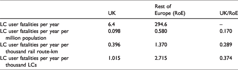
On the outset, it is useful to compare the performance of Great Britain Level Crossings with the European Level Crossings. Basic data on the railway safety performance for each country of Europe, labelled ‘Common Safety Indicators’ (CSIs) are reported by national authorities annually to the European Union Agency for Railways (ERA), and published by the Agency. The CSI is a major source of data for comparing the performance of Level Crossings in European countries. The data includes the number of Level Crossings by type and the causalities by type as well. A brief overview of the data is given in Table 1. 8
Fatalities to road and footpath users at level crossings: Europe: 2012–2016. 8
To improve the risk of near misses and fatalities different solutions are proposed and implemented at Level Crossings. In general, the ORR suggests that safe design, management and operation can significantly improve the user’s behaviour, which in effect will reduce the number of accidents and fatalities. Director of Rail Safety (Ian Prosser) and Technical Manager of Irish Rail (Cathal Mangan) suggested that implementation of new technologies like Automatic Barrier Crossings with Obstacle Detection is a solution to reduce the risk of fatalities. 7 All technology employed in the UK network must satisfy the “Network Rail Assurance panel Process (NRAP)”, which governs rail processes. When a change is introduced that could affect the risk profile of the Network Rail Infrastructure, NRAP ensures the compliance of the respective engineering processes and technologies with the Network Rail’s responsibility, health and safety systems. The Level Crossing Strategy and Risk Assessment are considered in detail within NR/L1/XNG/100/02 and NR/L2/OPS/100 standards. Furthermore, technologies must be approved through stringent business regulations and standards NR/L2/RSE/100/06 that have reached TRL8 or above. Risk components such as interlocking devices will be reviewed against the NR/L2/RSE/100/06 with approval weighed against the risk to the business. All aspects of any proposed system will be reviewed for redundancy ensuring that even small changes to the software system ensure system fail-safe expectations. 9
The new technology should not just detect an obstacle, rather communicate the information to the signaller so an appropriate decision is made by a relevant operator. The Obstacle Detection technology at a Level Crossing should be able to detect an object (any vehicle or pedestrian) and communicate the information to relevant signaller/operator or start the automated process of closing the barriers once the area is clear. The technology must check the area before it starts the process of closing the barriers and signalling the train. The new or improved technology must detect objects with more precision and within shorter time-frame. To avoid any misuse of such systems, it should only be implemented in Full Barrier Level Crossings, since the road users will misuse the other types of Level Crossings as some free way to cross the rail lines is still available. Therefore, the automated Obstacle Detection technology should be implemented at existing Full Barrier Level Crossings or others should be upgraded to Full Barrier Crossing before automating the process using this technology. To illustrate the above-mentioned strategy a decision tree is mentioned below in Figure 1. 10
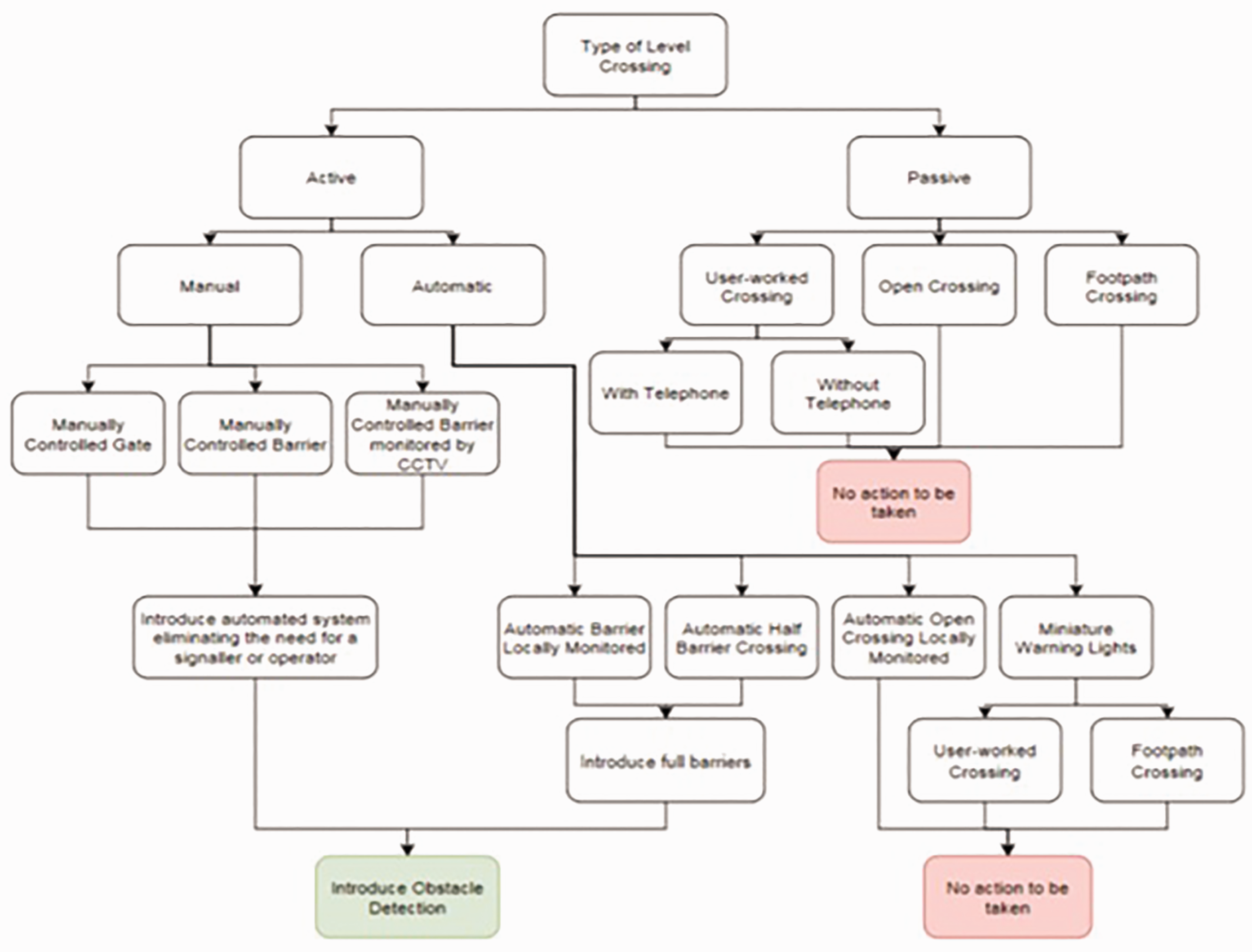
A generic flowchart of what type of Level Crossings should be automated. 10
It is essential to discuss the state-of-art within sensing systems utilized at Level Crossings or have the potential for detecting the objects. The obstacle detection system for Level Crossings is categorized into two main types; intrusive or non-intrusive. Intrusive sensors are installed under the tarmac or attached to the rail lines, which naturally makes the installation and maintenance very expensive and hard. The constant wear and tear shortens the product-lifecycle and regularly disrupts the train operations. The non-intrusive sensors are installed outside the rail tracks, hence it does not disrupt the rail operations during installation and maintenance. It generally has longer product-lifecycle. 11 The primary choice was intrusive sensors such as inductive loops but it is now complemented or entirely replaced with non-intrusive sensors for obvious reasons mentioned earlier. However, it is still necessary to discuss intrusive sensors to understand the demand for non-intrusive sensors.
Therefore, the present journal discusses and review two main areas of interest; Obstacle Detection Technology and relevant algorithm to post-process the information required to signal the operator before the train arrives about the condition at Level Crossing or start the process automatically. These sensors and associated algorithms will help make the automation process of Level Crossing more effective and reduce the risk of accidents and fatalities. The following Section I will discuss the sensors available or have the potential to detect obstacle at Level Crossing and the Section II will discuss relevant algorithms, which are required to post-process the information essential to make the decision or signal the operator. Finally, the Section Conclusion gives concluding remarks and some suggestions based on the information discussed earlier.
Measurement methods
Obstacle detection sensors
In literature, 12 the author describes Inductive Loops as “probably the most common form of vehicle detection”. It is also the earliest proposed solution to detect an object. The Inductive Loops technology has a wire embedded inside the road tarmac in a loop-like shape, which creates an electromagnetic field. The loop acts as an electrical circuit with variable frequencies ranging from 10 kHz to 200 kHz depending on the model used. The object e.g. vehicle when passed through the effective range, it induces eddy current and decreases the inductance. The decreased inductance actuates the electronics, which could be used to produce a simplified output. A detailed discussion on Inductive Loops installation and work principles is given in literature. 13
Since the working principle of Inductive Loops depends on inducing the electric circuits, the detectability for objects, which are made up of more composite and non-inductive materials is reduced. In the case of system failure, the embedded system is abandoned and a new system is installed, which can cause significant disruption in areas of high traffic volume and increase the risk of an accident when in proximity to rail infrastructure. Extreme weather conditions e.g. heavy rain or fog can adversely affect the system and result in low detectability. As such, inefficiency in poor weather conditions and extensive wear and tear make Inductive Loops a less favourable choice for Level Crossing application. 14
Another technique used for object detection mentioned in literature 11 is using strain gauges or piezometers, which measures the deformation of a material. A strain gauge can be installed inside a crossing area, which can detect the deformation of the crossing decking when a vehicle travels over it. The object's weight causes the decking and attached piezometer to deform, which changes its conductivity and hence signals the object’s presence above the sensor. Multiple piezometers can be used to interpret the direction of the object. Because piezometers are calibrated to detect vehicles and pedestrians, they may not be able to detect lighter objects, including children, which poses a significant risk to a Level Crossing. Made from rugged, weatherproof semiconductor materials, piezometers can perform better than Inductive Loops, however, the installation of these systems in the crossing decking makes them difficult to install and maintain.
Another method for obstacle detection at a Level Crossing is having two stereo cameras in one housing as mentioned in literature. 15 These two cameras are used to create a 3D representation of the scene is placed at a specific angle to cover an entire area of Level Crossing. These stereo cameras are integrated with an image-processing unit, where the optical axis, distortions, brightness and other errors are corrected. 16 From such corrections, the main advantage is to avoid false detection from shadows as mentioned in literature. 15 The main disadvantage of such a system is the cost of installation and its inability to detect where light availability is low.
The work in literature 17 proposed the use of a thermal camera, which creates an image based on the difference in temperature. The thermal imaging relies on the phenomenon of black-body radiation produced by all objects with a temperature above absolute zero, therefore, the system is unaffected with the change in weather or varying light conditions. 18 Thermal Imaging provides a high-quality image, easy installation and more lens options. However, the system is unable to detect an object, which is inert or produce the same radiation as the background scene. 19
Another technique mentioned in literature12,15 is ultrasonic detectors and Optical Beam method. The ultrasonic detectors use the transmission of an ultrasonic pulse and find the difference between transmitted and reflected pulse to detect the presence of moving or stationary object. The effectiveness of an ultrasonic detector relies on its working frequency and size, for instance, the ultrasonic detector with a frequency range of 40 kHz can detect an obstacle about 7 meters away. The only disadvantage of such systems mentioned is its price, cost of installation and its sensitivity in extreme weather conditions. 20 The Optical beam works on the same principle, where an optical beam is transmitted from one end of a Level Crossing and received on the other end. Any interference would detect the presence of an object. Even though the optical beam is easy to replace, the system still has high installation cost and requires multiple emitters to cover the whole area of a Level Crossing. If electrical waves are passed between the transmitter and emitter, the working principle is the same but it would not be able to detect any pedestrian.11,12
Another technique for obstacle detection mentioned in literature 21 is laser scanner for application in a Level Crossing area, which relies on the “the use of dense 3Dpoint clouds produced by a tilting 2D laser scanner”. This system would not be dependent on light conditions and object appearance as it is relying on binocular vision. The working principle of laser is the same as beam or SONAR, where it requires the emitter and receiver. The affectability of the laser system is reduced in adverse weather condition and since it requires multiple laser systems to cover the entire region of a Level Crossing the maintenance cost is high. In literature 22 the use of “Single Laser Rangefinders” is proposed, where the emitter and receiver are in one unit. Such systems are less complex but are unable to section areas of Level Crossing.
Another technique proposed was 3-D Laser Radar in literature. 23 It mentions the working principle as “A 3-D laser radar emits a laser pulse to an object, and measures the time that it takes for reflected laser to return to the radar (time-of-flight method) to acquire a distance to that object”. The work in literature24,25 proposed LiDAR, which works on the same principle of emitting near-infrared light. The reflected light allows the determination of speed, position and direction of an object. They both work on the principle of “Time of Flight (ToF)”, which can be used to determine the distance of an object. The LiDAR is compact, light and robust with high resolution, high range measuring accuracy and high scan rate. This allows the sensing system to detect even smaller objects such as a child. The initial cost and small life cycle of such systems is a limiting factor and it is hard to classify objects from such systems.
The use of “Camera” has been of much interest to many researchers for the application of object detection because of the easy installation and accessibility of the data for post-processing. In literature 12 it is stated for video sensing system that “An automatic process must be established to only transmit relevant information to the control room and train driver like the presence of an obstacle in the crossing zone at a critical time”. The video sensing system is also proposed in literature 26 and many different imaging processing techniques are applied to the sensing systems for analysing and automatically detecting objects in literature. 27 The use of Closed Circuit Television (CCTV) can replace the manual operator at a Level Crossing, hence it is the most preferable choice among researchers.
The drawback of such a sensing system is that any video system requires a sufficient amount of light to work effectively. During the adverse weather conditions such as heavy rain or fog, the detectability of such systems is reduced. The ability of video systems to distinguish objects and their properties in any given scene is a difficult task and requires extensive algorithms to process and analyse. For example, the video system is unable to differentiate between cardboard and a human child at a Level Crossing and will cause some level of threat. These situations require the intervention of an operator. 28 Usability of such systems is limited by an increase in false positives that is when an object is incorrectly detected. Most false positives are caused by a dynamic background, which resembles the real-world situation. This is not a failure of the algorithm, but a misunderstanding of its capability to differentiate risk between objects. However, this paper will introduce the Deep Learning algorithm, which enables the system to learn the representation on its own more effectively, hence, the model will be able to distinguish the object in a dynamic environment.
RADAR is another area of interest for many researchers and is mostly used obstacle detector at Level Crossings within the UK. The working principle of RADAR is same as emission and receiving of a signal e.g. radio waves, the received echo suggests the presence of an obstacle. Different types of RADAR are available whose working principle remains the same but differ in their post-processing to obtain information such as distance. For example, the pulse RADAR uses Time-of-Flight method and Frequency modulated RADAR determines the distance from the difference in the emitted and received frequency of an echo. 29
In literature 30 the implementation of RADAR in four-quadrant gate Level Crossing is discussed in detail. It discusses the use of Timed and Dynamic method of operation, where Timed method delay the closing of the barrier if some vehicle is present and in Dynamic the operation depends on the presence of the vehicle within the “Minimum Track Clearance Distance (MTCD).” Also in literature, 31 the RADAR is proposed as the main sensing system to detect obstacle with three safety configuration. In general, the RADAR is cheap to install or maintain and have a high life expectancy of approximately 10 years. Most of these RADAR works in the range of Gigahertz wavelength e.g. 24 GHz, which makes the system more robust in different environmental conditions. It can easily detect small and stationary objects at Level Crossings, which pose the most threat the crossing’s safety. 32
A single type of sensor cannot provide sufficient information about the object, which is required for application at Level Crossings. For example, the functionality of video camera-based systems is limited by the availability of light and RADAR is unable to classify between cardboard and a child. Given the limitations of using a single type of sensor, the use of two or more sensors, will add another layer of resilience and therefore overcome the shortcomings of a single sensor.
In literature 33 the fusion of colour Cameras and LiDAR is suggested, where colour Cameras can recognize distinctive object because of their colours and texture using different post-processing algorithms and LiDAR can discriminate such objects. The underlying issue with colour cameras is their inherent ambiguity due to the varying reflectivity of an object such as dry grass and soil. Also, the effect of the illumination spectrum on the perceived colour and the chromatic shift due to the atmosphere pose additional problems. The dynamic environment of a Level Crossing because of growing vegetation reduces the effectiveness of a Camera system. To overcome the mentioned problems, the LiDAR is proposed which can discriminate the moving vegetation from other smooth surfaces e.g. rocks or tree trunks. The LiDAR can eliminate the shadow effects as well as complimenting the Camera system more effectively. The problem with such fusion is the cost of colour Camera and LiDAR, particularly when two Camera are required to cover an entire area of a Level Crossing. The cost of LiDAR and the continuous maintenance make it a less preferable choice for obstacle detector at a Level Crossing.
In literature 34 the fusion of Multi-beam and Sector Scanning Sonars is proposed. Sector Scanners provides a set of scan lines by mechanically moving the unit to obtain an image, hence some image compensation would be required to produce an accurate image. To avoid this limitation, the multi-beam is proposed which will scan the entire area reducing the need for stabilisation. The problem with such fusion is high false alarms since neither of these mentioned sensors can differentiate the objects. To avoid this problem, the use of traditional image processing techniques, image segmentation or feature extraction is adopted. These limitations and the cost of such systems makes it a very un-preferable choice for the application at Level Crossing.
The most commonly used sensor fusion for Level Crossing application is proposed in literature, 35 which compliments the RADAR system with the LiDAR. RADAR is used as a primary obstacle detector to cover an entire area of Level Crossing using multiple-sensors. The data is post-processed to obtain further information about an object such as speed and distance. The RADAR, however, may not be able to detect small density objects. To avoid such limitation, the use of LiDAR is proposed, which can detect and obtain a detailed map e.g. 3 D scene of a scenario. The LiDAR can detect small density objects, which are missed from the RADAR. The LiDAR is normally within a glass unit; therefore, the presence of dust or small water droplets affects the functionality of the system. To overcome such problem regular maintenance is required, which further increases the cost of the system. Even though, the fusion of RADAR and LiDAR is a promising solution but have certain limitation such as the cost of the units and regular maintenance.
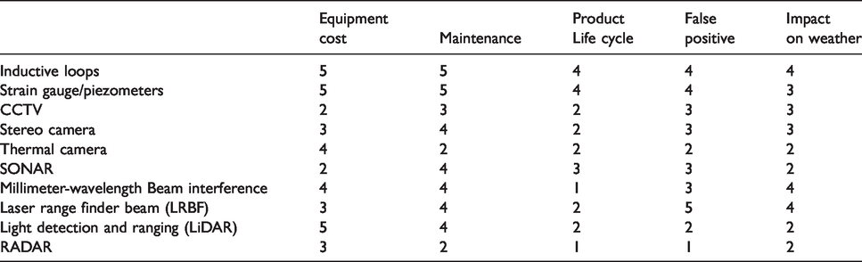
At this point, it is necessary to provide a summary of all the technologies mentioned below Table 2, scores each technology 1 (leading) – 5 (lagging) for each technology concerning certain parameters e.g. Cost, Maintenance etc.
A brief summary of all technologies discussed. The score 5 represents the worst choice, while 1 represents the best choice with respect to mentioned parameters e.g. cost or lifecycle.
Algorithms
The data received by any of the aforementioned sensors require some sort of post-processing before it can be used effectively in any given application. The post-processing techniques may include image-processing, feature extraction, image segmentation or foreground detection. The ultimate purpose of such an algorithm is to identify any present obstacle at a Level Crossing, which will either start the automated process of closing the barrier or warn the train driver for any threat.
Since one of the most commonly used sensing system at Level Crossing is Video Camera, which provides a continuous stream of live video to process, analyse and detect for any obstacle. The following discussion will highlight most of these algorithms that can detect any foreground from the background image. Among these mentioned algorithms, the most common method is to subtract the foreground from the background pixels. The problem with such an approach is that the background scene at a Level Crossing is a dynamic environment, where the algorithm must be able to adapt and update the background pixel continuously. The present work will also suggest the use of Deep Learning Techniques; a subset of Machine Learning Algorithms that automatically detects the representations from the objects and classify them with high accuracy.
The work proposed in literature 36 introduces the algorithm that uses the “Single Gaussian-SG”, which fits the Gaussian probability density function on the last ‘n’ pixel’s value. To avoid fitting the density function for every new frame the mean and variance are calculated. To detect any foreground, the given value is compared with the threshold value. The work in literature 37 discusses the use of Hue-Saturation-Value (HSV) compared with the traditional use of Colour Scheme (Red, Green and Blue- RGB), which is more robust to illumination changes and partial camouflage. However, the use of “Single Gaussian” is suitable for the indoor environment, where the change is minimal.
For outdoor application, the work in literature 38 proposed the use of “Mixture of Gaussian-MOG”. Each pixel is modelled using “Mixture of Gaussian” and each model use one-line approximation to update the model. The optimal number of Gaussian filter is updated according to the given environment. Another work in literature 39 models the background using three Gaussian filters representing the road, the vehicle and the shadows, where the intensity of each pixel is used for this categorisation; the darkest component is labelled as a shadow, from the remaining two the one with the highest variation is classified as a vehicle (obstacle) while the last one is classified as a road. The problem with such models is the noise and clutters in a given environment, therefore, the work in literature 39 proposed the use of “Mixture of General Gaussian-MOGG”. The work in literature 39,40 uses the Expectation-Maximisation (EM) and the K-Mean methods for MOGG model that adapt to the data more and is less sensitive to over-fitting. However, the model recovery time to false alarms is very slow and works poorly with a highly dynamic environment such as Level Crossing with high vegetations.
The work in literature36,41 introduces another technique that uses the probability density function using the K estimator on a recent sample (N) of intensity values. From the normal Gaussian function, the background model is obtained using Kernel Estimation- KE Function. The foreground detection is possible using a threshold value, which is also used to obtain two more models; Short-Term background model and Long-Term background model. The Short-Term model eliminates persistent false-positives, whereas, the Long-Term model reduces the number of false-positive detection. The use of these two updated models makes the system more effective and reliable for dynamic background environments. 42
Another algorithm technique is mentioned in literature, 43 which suggested the use of “Subspace Learning-SL”. The Subspace Learning is divided into two main stages; Reconstructive and Discriminative. The Reconstructive Phase learns information from the data through unsupervised learning and updates the data in increments, which is beneficial for real-time applications. The Discriminative Phase requires supervision to separate the data using a linear transformation, which is used for classification. The training requires the data in batch, hence, the data should be available in advance which is a downside. Also, the model is computationally extensive and creates a lower-dimensional classification space. To avoid these limitations, different works proposed different solutions such as Subspace Learning using Principal Component Analysis (PCA), 44 Subspace Learning using Incremental Non-Negative Matrix Factorisation,45,46 or Subspace Learning using Incremental Rank Tensor. 47
There are some algorithms which are used to separate the data used for classification. The work proposed in literature 48 is “Support Vector Machine-SVM”. The SVM utilises a hyperplane in high dimensional space to separate the data by minimising the margin between the hyperplane to the data. The output is divided into two sets for unbiased training; 80% for SVM training and 20% for two parametric minimisations. If the probabilistic output is greater than the distance of hyperplane to the data, the output is considered as either a new moving foreground or newly updated background.
The model proposed in literature 49 uses the “Support Vector Regression–SVR”, which model each pixel as a function of its intensity. The pixel values of each frame contain two outputs, one correspond to the intensity of the pixel and other value represent the confidence of that pixel belonging to the background. Once trained, the model uses a linear regression function where the output of SVR represents the confidence of each pixel belonging to the background. The SVR model keeps updating the background scene by labelling the pixel as background if the confidence lies within the threshold range.
The use of threshold value and probability function limits the functionality of the proposed algorithm. To overcome this issue 50 proposed the use of “Support Vector Data Description-SVDD”, which uses the boundary feature. However, the optimisation is computationally intensitive and during maintenance, all SVDD must be recomputed.
The work in literature 51 proposed the use of Temporal differencing and Image Template Matching to detect and track the objects in a video sequence. The method is robust to background clutter and a slight change in the object’s presence would not significantly affect the performance.
Another technique is mentioned in literature 52 is the use of “Temporal Median Filter-TMF”. The TMF uses the median value of the last frame to model the background, which increases the stability of the background. However, the TMF is not able to accommodate the model in the rigorous statistical description and does not provide a deviation measure for the adoption of the threshold value.
The work in literature 53 proposed the use of “Co-occurrence of Image Variation”, which works best if the background object belongs to the same object with least variation. The method can be divided into two main steps; the Learning Phase and Classification Phase. The Learning Phase calculates the eigenvector value and in Classification Phase the input value is computed along with its corresponding eigenimage variation value. If the calculated value is close to the calculated eigenvalue then the new and old pixel value is considered as a background model. However, Level Crossing is a dynamic environment with a variant distinct object, which makes the proposed algorithm a very poor choice.
A similar kind of algorithm is proposed in literature, 54 which uses the “Principal Component Analysis-PCA”. The PCA is further divided into two main phases; training phase and online transformational phase. The training phase captures the dataset to obtain the transformation matrix U between the original and transformed space. In the online phase, the measure received are compared with the values obtained in the training phase. If the values differ significantly then it is considered as a foreground object. A more generalised form of PCA is “Independent Component Analysis-ICA”, which can differentiate background and foreground, particularly stationery and small objects. For outdoor applications, the use of colour ICA is proposed in literature.55,56
Some other work proposed the fusion of two techniques such “K-Mean clustering” algorithm on a modified “Lucas-Kanade” method, 57 “Lucas-Kanade” technique with “Haris Corner Points” in literature 58 or “Histogram of Oriented Gradients-(HoG)” algorithm with a Support Vector Machine-SVM in literature. 59
The discussed algorithms work on a principle of either subtracting the foreground pixel with the background pixel and detect the presence of an object using some threshold value or some supervised programming is required to train from the data for classification. These limitations affect the functionality of the system as the Level Crossing is a dynamic environment and most the time the required data is not sufficient for manual programming. To overcome these problems, the work in literature 60 proposed the use of Deep Learning technique. Deep Learning is a subset of Machine Learning, which can automatically learn the representation from the images and classify the given categories without any supervision. It consists of multiple processing layers and can learn representation using backpropagation algorithms. Once enough representations are learned, very complex functions are learned used for different applications such as classification and detection.
The Deep Learning model learns features for the general-purpose avoiding the need for human-engineering, for example, the classification model learns small features like edges, orientation and location to more complex such as motifs or parts of objects with assembled features. From such learned models, it can detect and classify objects very effectively. The model does not require any supervision or regular increment of data to update the existing system. Another advantage of Deep Learning is its ability to integrate with other existing sensing systems such as RADAR, LiDAR and Video System. For example, the Deep Learning model can classify and detect objects in real-time using the live stream of video from Video Sensing system. The training of such models requires high computational power, however, once trained the network can work in real-time with even 15fps rate of processing power. The work in literature61–63 mentions details about the training and computation power.
Some work has discussed the integration of Artificial Intelligence- A.I with different sensing systems. For example, the work in literature 64 discussed the integration of Video Camera with the use of A.I and the work in literature 65 discussed the use of TensorFlow (an open-source library for Machine Learning) to detect objects. Another work discussing the integration of Vision system with A.I is mentioned in literature. 66 These work and the mentioned discussion on each given algorithms suggest the importance of Deep Learning techniques, which can automate the process of learning and classifying the objects.
These algorithms could be categorised into two main types; Detection and Classification. The detection category can detect an object by subtracting the foreground pixel from background pixel, whereas, the classification type can separate the data into different categories for classification. Below in Figure 2 is a decision tree, where the order of preference is from top to bottom.
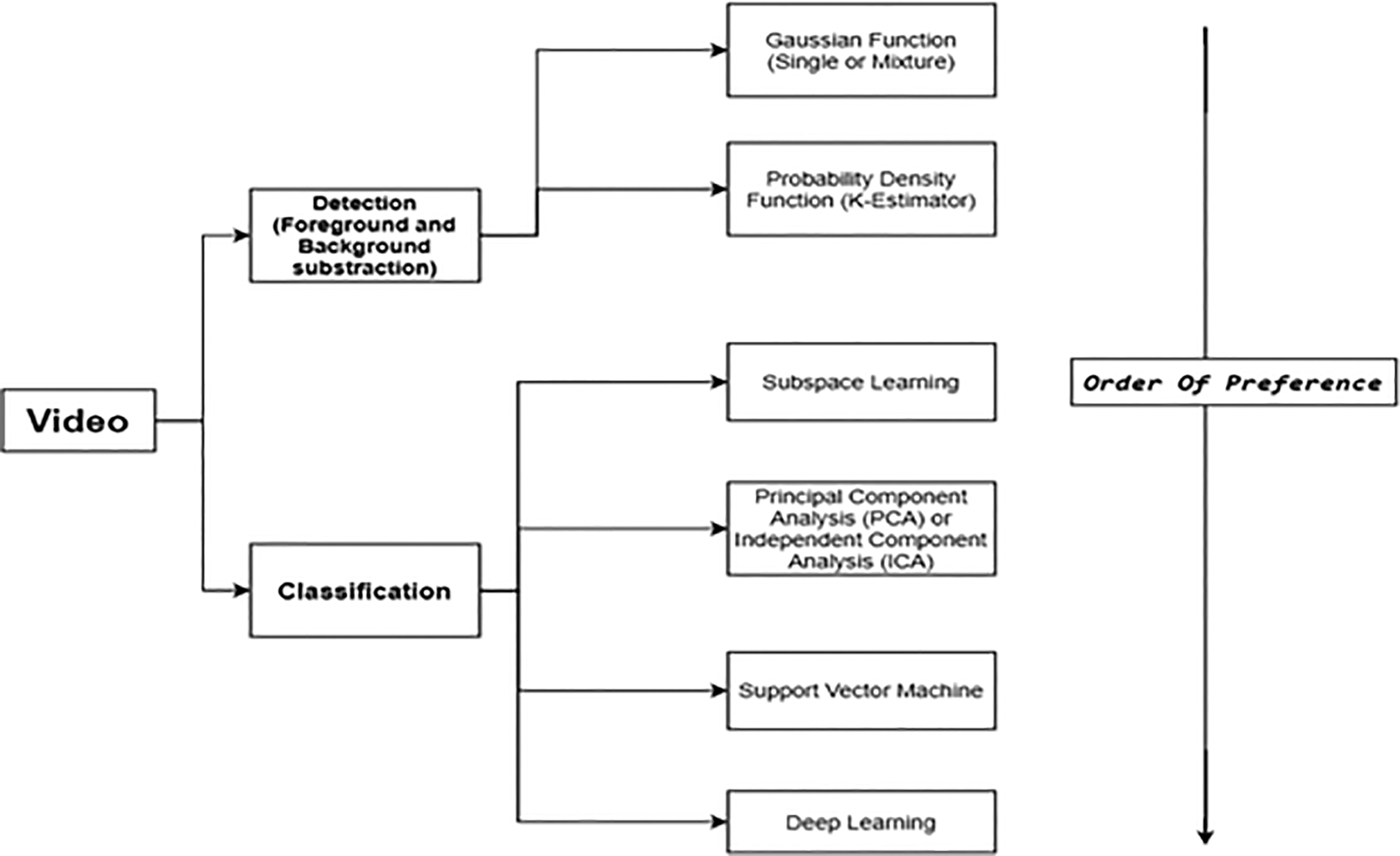
Decision tree for selection of appropriate algorithms depending on identification requirements.
Conclusion
A comprehensive survey of different sensing technologies is presented in this paper. The Inductive Loops were the earliest solution for Level Crossings, which was replaced by non-intrusive sensors e.g. CCTV, LiDAR or RADAR. Currently, the most common sensing technology used at a Level Crossing is RADAR, which is often complemented with LiDAR. From the mentioned statistics and discussion, it is necessary to replace or upgrade these existing technologies along with its associated algorithm to automate the operational cycle.
Intrusive sensors were the earliest proposed solution for obstacle detection at Level Crossing. However, the inability of these sensors to detect the lighter objects e.g. children or vehicles which use more composite and non-inductive materials, make these sensing systems a less favourable choice. These intrusive sensors were superseded with alternative Non-Intrusive sensors e.g. SONAR, CCTV or RADAR etc. Each non-intrusive sensing system has limitations, which should be considered before its implementation at Level Crossings. For example, a Stereo Camera is not preferable because of its cost and problems associated with image detection in dynamic background situations. Also, techniques such as thermal imaging cannot detect non-braked or inert objects at Level Crossings.
Different algorithms are used to detect foreground objects from a known background within a scene such as a Level Crossing. These algorithms must update the data that constructs the dynamic background because of the varying light and weather conditions. Such an algorithm could be a simple Gaussian probability density function on each frame of a video, which is used to calculate the mean and variance. These calculated values are compared with a threshold value to detect any foreground. In addition to detection, the kernel density estimation could be used to update the model, a necessary step for the subsequent foreground detection. Some algorithms are used to extract information and use that information to classify objects e.g. Subspace Learning, while others obtain binary output from a Support Vector Machine, which could be used for training and updating the background model. Other algorithms compare the neighbouring pixels, to classify different objects within an image e.g. Co-occurrence of Image Variations. Independent Component Analysis (ICA), which is a generalised technique of PCA, is the most commonly used method for background subtraction. ICA can detect small and stationary objects and is less sensitive to noise. Finally, modern approaches such as Deep Learning allows the detection and classification of objects without explicit programming. In the Deep Learning approach, the algorithm learns features from training data e.g. images of vehicles and pedestrians, which enables the system to detect and classify objects while not depending on the background model.
The findings of this review suggest that one sensor is not sufficient to provide information for adequate obstacle detection in this scenario. The fusion of two or more sensors can provide a more robust approach, which can support the interpretation and classification of obstacles more effectively. Multi-sensor fusion adds additional layers of resilience and can significantly reduce the risk posed when only one sensor is used. RADAR systems can detect stationery and small objects within a Level Crossing area, they are cheap to install and have a high life expectancy. However, RADAR is not able to associate the threat level between different detected objects e.g. children or litter blew through the scene. A video camera with an associated classification algorithm can detect and classify objects. This, in turn, could associate the threat level with each object.
The fusion of RADAR and LiDAR is currently used at various sites of Level Crossing, however, the cost of LiDAR and incompatibility of LiDAR to cover an entire region of Level Crossing, also, the low life expectancy of LiDAR makes it less preferable choice. From the discussion above, the fusion of CCTV and RADAR is proposed with Deep Learning algorithms. The live feed from a CCTV camera is fed to a Convolutional Neural Network, which automatically learns the representations and can classify and detect the obstacle of interest such as pedestrian and vehicles. The camera, however, is unable to work effectively in adverse weather conditions. For such instance, the RADAR sensor is fused with the CCTV camera. The RADAR can work effectively in adverse weather conditions, specifically where the camera fails to detect an object. The categorisation and classification of such objects allow authorities like RSSB and ORR to carry out Risk Assessments. The Risk analysis will allow the concerned authorities to carry out relevant actions against the specific object, which pose the most threat to the Level Crossing. This will significantly and effectively reduce risk and accidents.
Therefore, the proposed solution for automation of Level Crossing area, which will reduce the risk of accidents and fatalities is the fusion of CCTV and RADAR along with the Deep Learning algorithm. In addition, the low cost of camera systems implies that multiple cameras could be installed for redundancy. The implications of Deep Learning algorithms is an interesting area of research as it allows progression and more effective and robust models from same existing sensors. More data from the Level Crossing area could be used to re-train the network with more accuracy and avoid any bias. The RADAR is another field of research within Deep Learning area and could be suggested for future work. 67 For example, the RADAR could be used to obtain micro-Doppler signals, which are distinguished for each object. These micro-Doppler signatures are crucial in training another Convolutional Neural Network, which will allow ensemble models to be built for better resilience and effective results.
Footnotes
Declaration of Conflicting Interests
The author(s) declared no potential conflicts of interest with respect to the research, authorship, and/or publication of this article.
Funding
The author(s) received no financial support for the research, authorship, and/or publication of this article.