
Abstract
The current performance requirements for the global rail industry demand that trains are more reliable, efficient and can accommodate an increased capacity for more passengers. Lightweight construction of rail vehicles is thus required to meet these requirements. This paper has identified the key components for lightweighting of rail vehicles using fibre reinforced polymer composite materials. A methodology used to select and rank those metallic components suitable for redesign in composite, developed as part of the ACIS (Advanced Composite Integrated Structures) UK project is described. From the audit, five demonstrator components – a cantilevered seat bracket, luggage rack module, intermediate end structure, body side structure and roof structure – were identified by the consortium using the methodology. These are components that the consortium believes to be the most suitable to demonstrate the benefit of a composite replacement in terms of integration potential, lightweighting benefits and commercial viability. Furthermore, rail car body structural components, forming the primary structure of a rail vehicle, were determined to be the most optimal components to replace in composites for maximum lightweighting of the sprung mass. It was estimated that a composite redesign of these components would result in a mass savings of 57% for intermediate end structures, 47% for body side structures and 51% for roof structures.
Introduction
The drive to reduce greenhouse gases associated with carbon dioxide (CO2) emissions is particularly relevant to the global transport industry, which accounts for approximately 25% of the total emissions generated. 1
Specific emissions targets for European railways were agreed and highlighted in the European Rail Sector Sustainable Mobility Strategy 2010. 2 This strategy provides a unified approach to environmental and sustainability topics echoed in the UK’s Rail Technical Strategy 2012. 3 Rail vehicle lightweighting using fibre reinforced polymer (FRP) composite materials is central to both strategies. This is recognised as a means of reducing CO2 production through lower energy consumption to deliver improved rail capacity and performance.
In 2018–2019, 1.76 billion rail passenger journeys were made in Great Britain, amounting to 67.7 billion passenger kilometres. This was a 2.2% increase compared to the previous year and is the highest rate of growth since 2015–16. 4 This growing demand on the UK rail network coupled with trends of increasing mass of rail vehicles, 5 accentuates the necessity for lightweighting of rail vehicles. These heavier vehicles have an adverse effect on the rail network which manifests itself as track damage. This ultimately results in increased infrastructure maintenance and renewal costs. This damage arises from both the gross vehicular weight (GVW) bearing on the track as well as impact forces associated with dynamic action of the unsprung vehicle mass.
In comparison to the aerospace, automotive and marine industries, the railway industry has been perceived as slow to integrate lightweight materials (primarily FRP composites) into their structures. The main barriers to the widespread adoption of FRP composites have been cost, fire performance and issues of maintenance in the railway environment and over the lifetime of the vehicle. However, composite design can reduce manufacturing costs (from a life-cycle costing perspective) by reducing the number of parts, assembly steps and assembly time. 6
The ACIS (Advanced Composite Integrated Structures) UK rail project (funded by the Rail Safety and Standards Board, RSSB/13/EIT/1744) sought to address this challenge of rail vehicle lightweighting. A team of engineers from Bombardier Transportation (lead), the University of Nottingham, Haydale Composite Solutions and the National Composites Centre developed a methodology to identify the most commercially viable components of a rail vehicle to be lightweighted by redesign in composites. This paper provides a focussed review of composites in the railway industry and presents the findings of the ACIS project.
A review of composites in the railway industry
Steel and aluminium have long been used as structural materials for rail vehicles. These metallic materials possess good strength, formability and weld-ability properties coupled with a relatively low cost, which makes them a versatile option. However, the desire to achieve a lightweight design and reduce production costs are the main two driving forces behind the introduction of new materials in rail. 7 FRP composites are one such material system that meets these aims. These materials have high specific properties and can form complicated, three-dimensional profiles suited to rail vehicle design.
Rail vehicle design is typically separated into major modules such as the intermediate end, body side, roof, cab front, underframe and bogies. Composites for semi-structural interior applications tend to utilise glass fibres and low-cost grades of thermoset polymers. Only for bespoke projects, such as high-speed trains, where weight reduction is a necessity, are carbon fibre and higher-performance resins, such as epoxies used.
Composite materials for railway applications
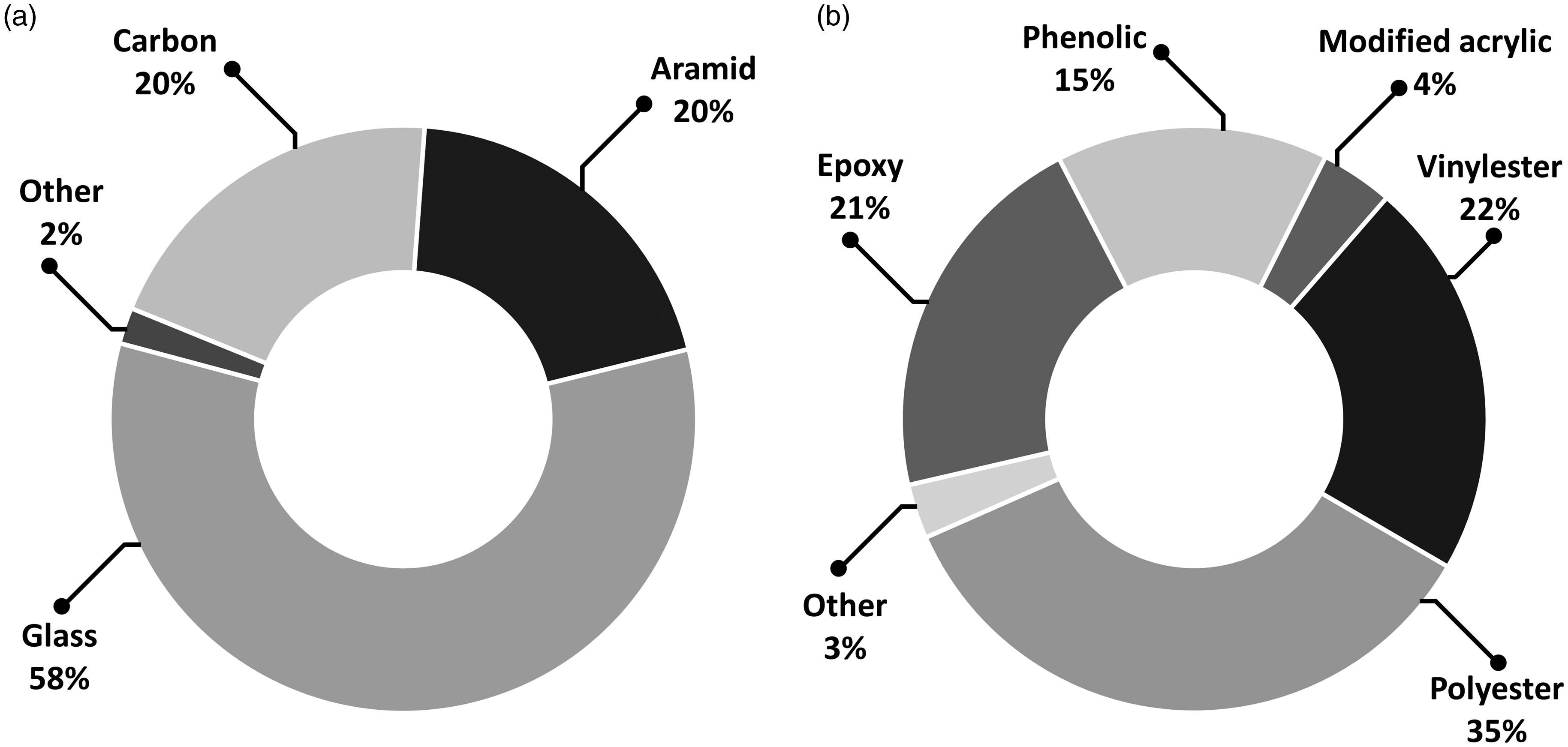
The fire, smoke and toxicity (FST) requirements specific to the rail industry as stated in the British European standard BS EN 45545-28 severely restrict material choice, and the introduction of novel materials. In terms of reinforcement fibres, glass fibres are most commonly used for rail applications due to good mechanical properties and their low cost in comparison to carbon and aramid fibres. These fibres are usually used in the form of chopped strand mat (CSM) and continuous filament mat (CFM) for most interior rail applications. While these glass fibre composite structures are lightweight, the lack of fibre alignment in the formats currently used, limits the structural performance.
In terms of resin selection, thermosetting resins such as polyester, vinylester and epoxies are most commonly used for rail applications. 9 However, an issue with these resins is their FST performance. For example, the unsaturated form of polyester burns easily resulting in smoke and toxic fumes. To overcome this, fillers and additives are used to improve fire retardancy. However, this tends to increase the viscosity of the resin making it difficult to process and thus limits the widespread use of this resin for rail applications. Phenolic resins are inherently fire retardant and evolve low levels of smoke and toxic fumes. These are typically used for rail vehicles designed to operate in tunnels, such as on the London Underground. The most stringent FST requirements for rail vehicle design are those specified for the London Underground. They require rail vehicles to comply with the superseded British standard BS 6853, 10 category 0 and 1a performance levels which are more rigorous than the Hazard level 3 category, stated in the current British European standard BS EN 45545-2.8,11 However, phenolic resins cure by a condensation reaction which leads to porosity within the matrix, resulting in brittleness. This makes phenolics unsuitable for structural components.
Figure 1 provides a summary of reinforcement fibres and matrix resins commonly used in the manufacture of composite components for rail vehicles. Although the source is a snapshot from 1997,
9
it still provides a useful summary of the relative usages as discussed above.
Summary of (a) reinforcement fibres and (b) matrix resins used, in terms of volume, in the manufacture of composite components for rail vehicle applications.
9
A rail vehicle is typically fabricated with either lightweight, stiff panels or more commonly, sandwich panel structures (consisting of two FRP skins encapsulating a lightweight core). Sandwich panel structures are used for cab ends, body sides and flooring using polymer foams, balsa and honeycomb cores. Balsa, a low density sustainable wood, is a common choice due its low cost and was used for the C20 Stockholm metro car (which commenced service in December 1997) supplied by Adtranz. 9 Another example is the flooring panels of the Kuala Lumpur Monorail manufactured by Flexadux Plastics in the UK. End-grain balsa clad in a phenolic laminate was used to fabricate large (approximately 3 × 3 m) floor panels. 9
Moreover, sandwich panel structures utilising honeycomb cores have become the preferred fabricating route for rail vehicle bodies and interior panelling. These have high strength, good impact and energy absorption properties. Examples of sandwich panelled rail vehicles include: Schindler Waggon’s Revvivo, Munico and Neitec vehicles, 12 the Korean Tilting Train eXpress (TTX) 13 and Bombardier’s C20 FICAS. 14
Composite manufacturing processes used in rail
Composite manufacturing processes used within the rail industry are driven by the requirements for simplicity and low cost. Since the majority of rail components fall between the range of 50–5000 parts produced per year,
15
the low volume production dictates mainly manual lay-up (used for part production of <100 parts/year) and spray lay-up techniques to be used which are simple but labour intensive. A summary of the manufacturing processes used in the railway industry is shown in Figure 2. This process breakdown is a snapshot from 1997,
9
so while the percentage distributions may vary today, it is still a useful comparison.
Summary of composite manufacturing processes used in the production of composite rail vehicle applications, adapted from research presented by Robinson et al.
9
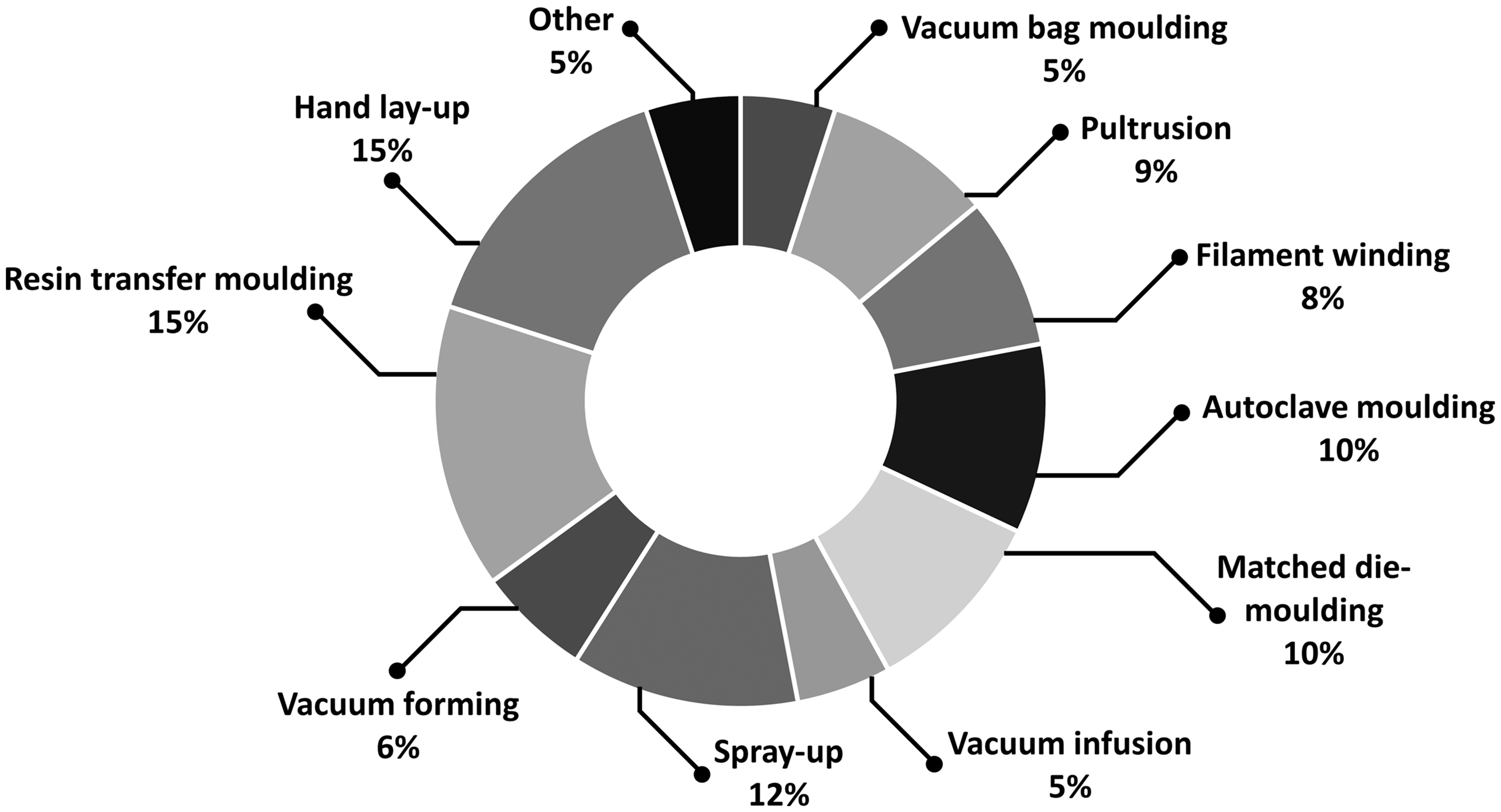
Other common methods include vacuum infusion which is suited to larger parts and low volume production (<500 parts/year). This was used for the manufacture of the roofs on the Bombardier TALENT trains in Germany, 2003. Resin transfer moulding (RTM), a liquid moulding technique, is another process (typically used for medium volume production of <30,000 parts/year) which has been used for production of the Strasbourg light rail vehicles (Bombardier FLEXITY). This vehicle features both seat components and sliding doors manufactured in the UK by Aztec. Matched die-moulding of sheet moulding compound (SMC) has been used to fabricate seat shells, where the large volume of production has been able to justify the high tooling costs.
There have been a few notable examples of large-scale manufacturing of composite structures in rail vehicle design in the production of rail vehicle car body structures. These examples represent bespoke projects where the manufacturing volume was low (typically one-off production) and, therefore cost was not a constraining requirement. The transition towards automated composite manufacturing processes is currently hindered by the low maturity of composite use within the rail industry and lack of knowledge in this area.
Composite rail projects
Research into advanced composite structures for passenger rail vehicle bodyshells, bogies, and wheelsets is predominately led by Europe, Korea and Japan. The current research is driven by the need for lightweight and energy absorbent composite structures to replace metallic structures.
As part of the modular urban guided rail systems (MODURBAN) European rail project, the mass breakdown of a typical six-car-set metro vehicle was quantified (see Figure 3).
16
It concluded that the bogies and car body structures are the two largest mass contributors for a typical passenger rail vehicle, accounting for 65% of the total tare mass. They are thus prime candidates for lightweighting in rail vehicles.
A typical mass breakdown for a passenger rail vehicle, adapted from research presented by Carruthers et al.
16
HVAC refers to heating, ventilation and air condition systems.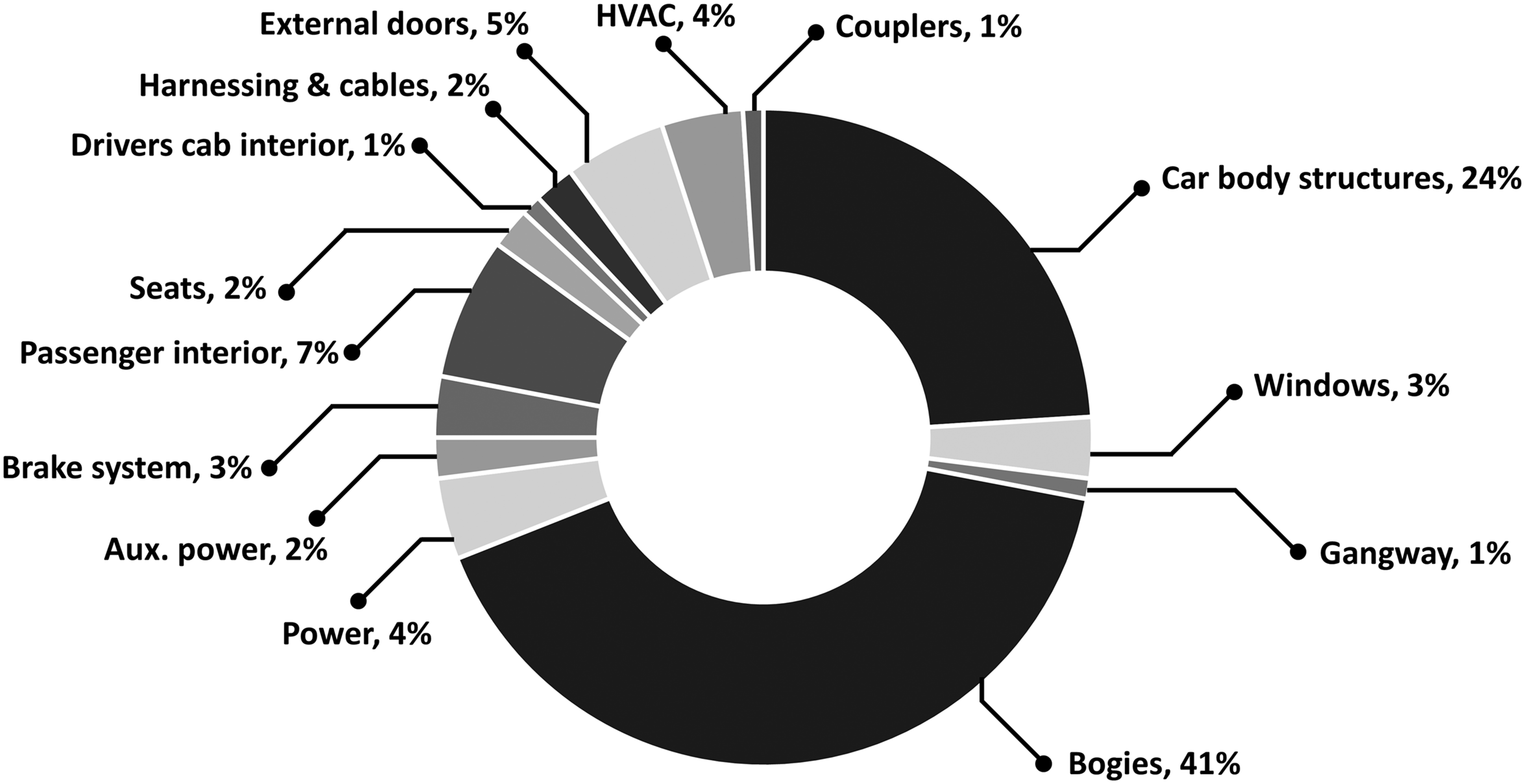
Summary of composites in rail vehicle design. 7
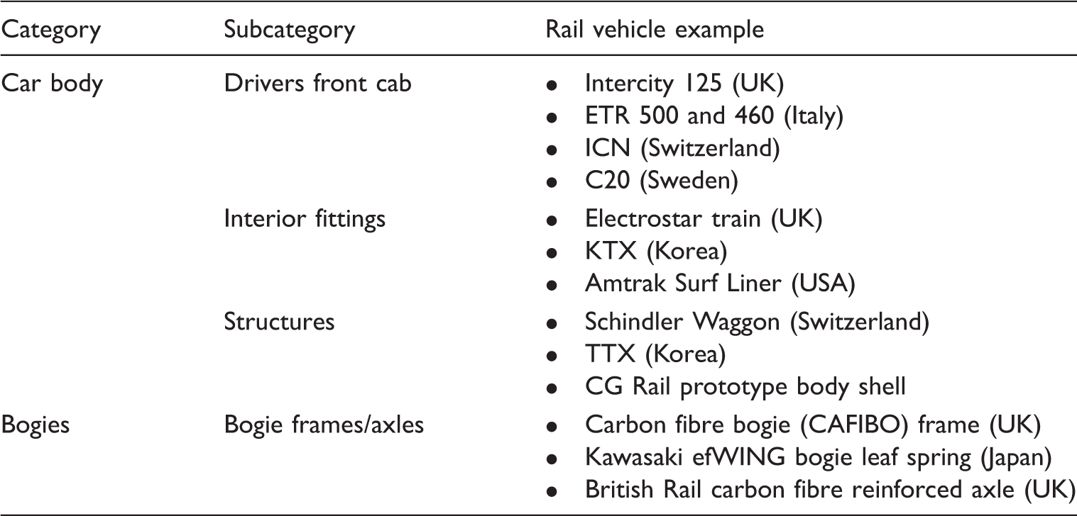
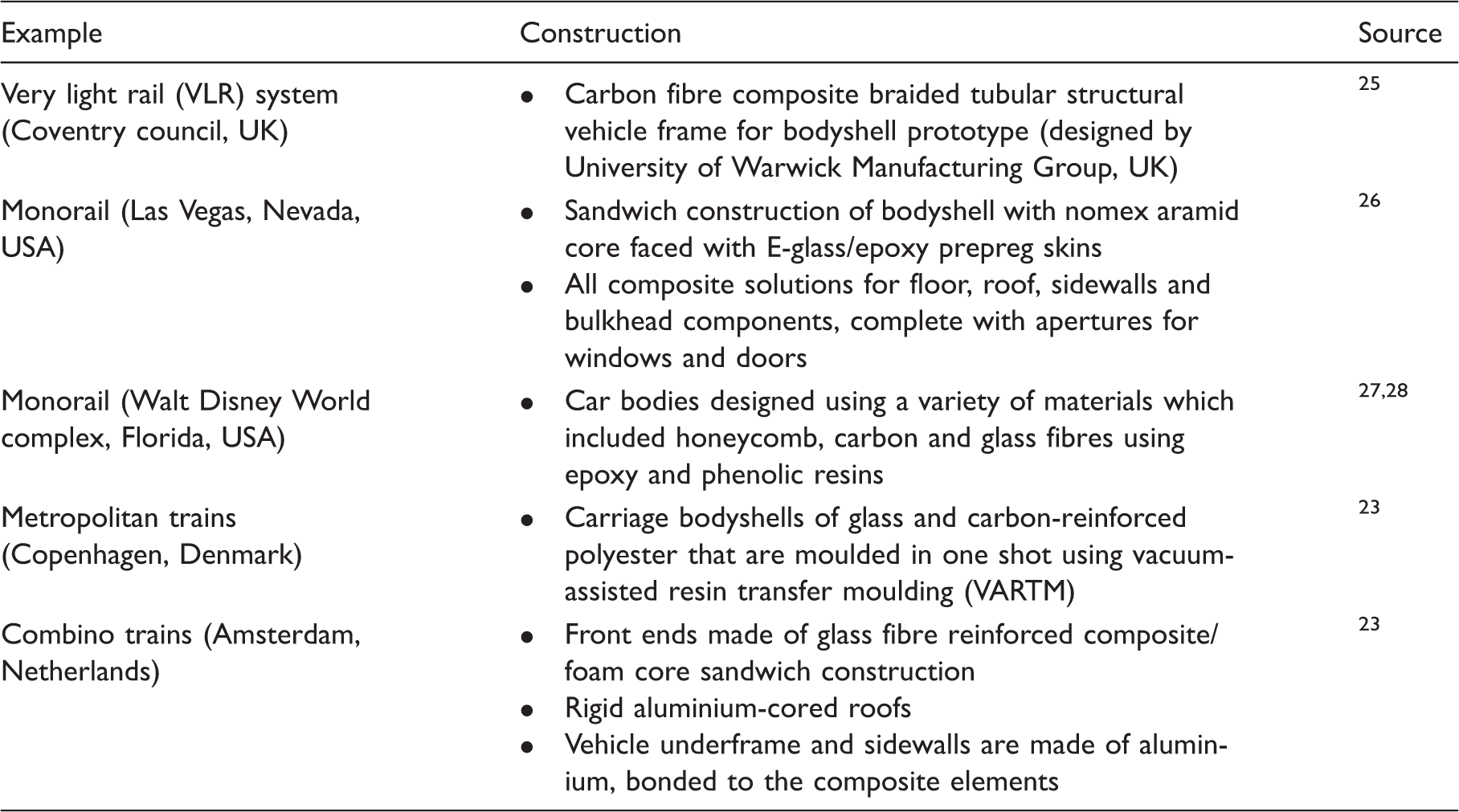
As seen from Table 1, there are numerous examples of composites incorporated into the bogies and car bodies of rail vehicles. In particular, the greatest use of FRP composite materials by volume in rail vehicle design have been focussed on the car body structures.
Pertinent research into the use of advanced composite materials for rail vehicle car body structures has been carried out by The Tokyo Car Corporation, and the East Japan Railway Company investigating the use of carbon fibre reinforced plastic (CFRP) roof shells fixed into an aluminium frame structure using a novel transition welded joint. 17 Similarly, the Japanese Railway Technical Research Institute has developed and tested hybrid aluminium-CFRP structures. An automated pultrusion process was used to produce the CFRP panels, which were then riveted onto an aluminium frame. 18 SNCF (France) investigated the use of lightweight structures consisting of carbon and glass reinforced epoxy around a foam or honeycomb core for use in their double decker TGV high-speed trains. 19
Examples of monolithic composite construction of rail vehicle car bodies.
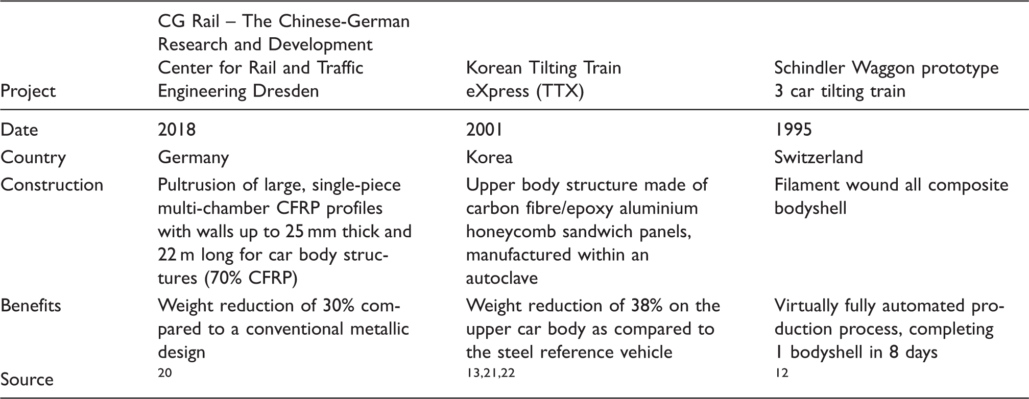
There are numerous benefits resulting from a composite rail car body construction. Firstly, a reduction in mass of the primary structure can provide a cascading mass saving benefit for the rest of the vehicle and components in terms of the traction system, suspension and brakes. 29 This would in turn reduce track infrastructure damage and wear on the wheels and bearings. 30 Secondly, a total rail vehicle mass savings of 20–30% is estimated for composite car body construction. This correlates to reduced energy consumption during the use phase and an estimated reduction of approximately 5% of CO2 emissions.31,32 Thirdly, the life cycle costing (including operational and maintenance costs) is expected to significantly decrease. Blanc et al. 33 carried out a life cycle costing analysis on the Korean Tilting Train eXpress (TTX). The estimated energy savings of this high-speed train with different material car body constructions were determined. This analysis showed that a composite car body scenario is 42% less energy demanding than a stainless steel scenario, and 21% less energy demanding than an aluminium scenario.
In conclusion, the literature regarding the benefits of mass reduction of rail vehicles has been investigated, quantified and well documented.31,34,35 However, limited research has been conducted to quantify the mass saving potential of composite rail vehicle component replacement and to determine whether such a replacement is commercially feasible.
Selection and ranking methodology
As part of the ACIS UK rail project (funded by the Rail Safety and Standards Board, RSSB/13/EIT/1744), a selection and ranking methodology for composite replacement of rail vehicle components was developed to identify key components for lightweighting. A comprehensive rail vehicle audit of a Bombardier Electrostar (EMU passenger train) was carried out. The focus of the audit was on the sprung mass of passenger rail vehicles. Bogies and propulsion equipment (unsprung mass) were not included within the scope of this project.
The methodology was developed to evaluate vehicle components consisting of three main steps: (1) Preliminary component ranking, (2) Economic potential for a composite component and (3) Composite component evaluation, as shown in Figure 4. A comprehensive description of this methodology is provided below using the vehicle audit as the source of initial component identification.
Selection and ranking methodology used to evaluate the commercial viability for a composite replacement of rail vehicle components (including the outcomes for example components).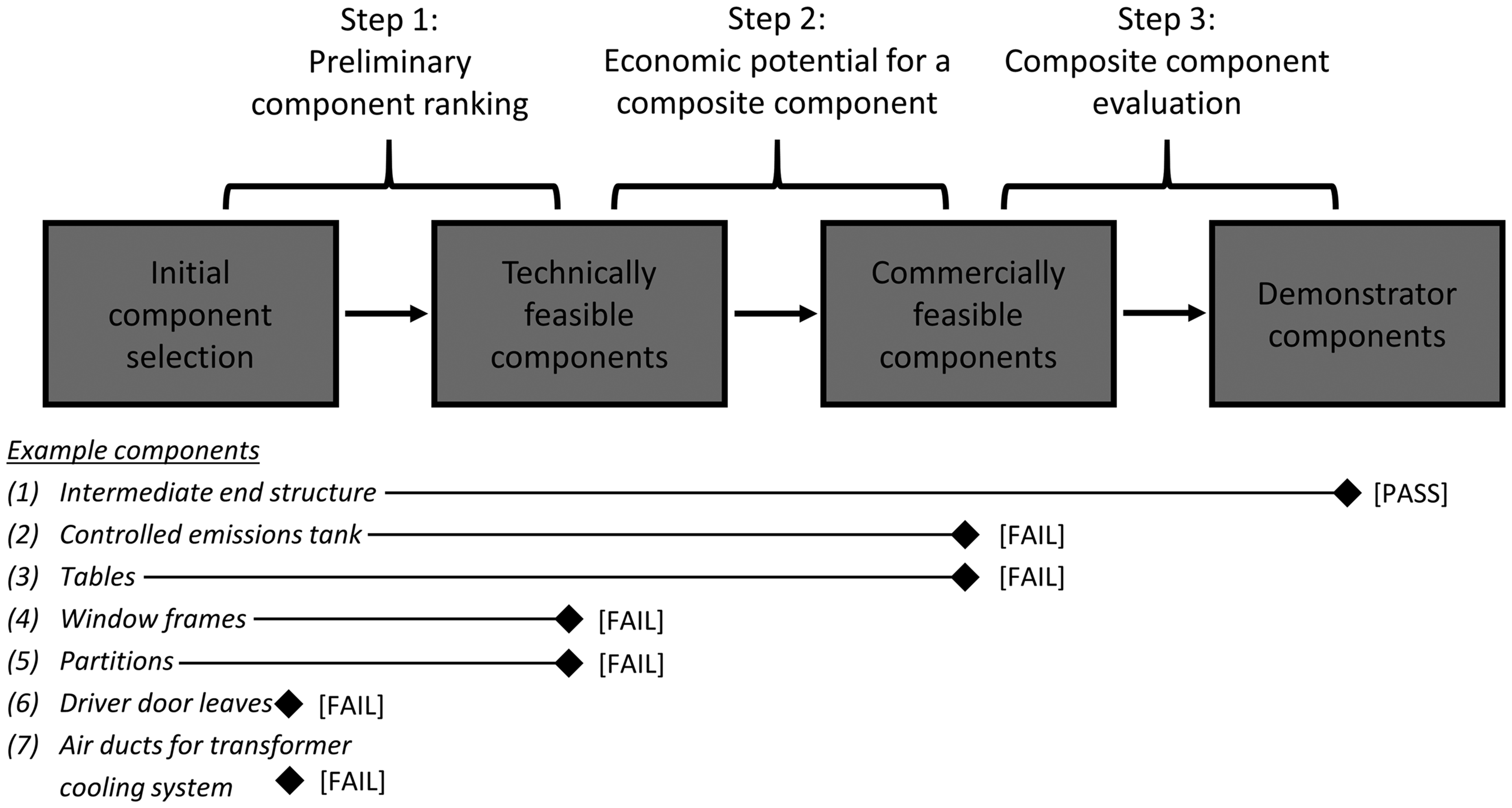
Step one – Preliminary component ranking
The aim of this first step is to identify which of the existing metallic components would benefit from lightweighting. Additional factors considered included the potential for part integration, improved mechanical properties and corrosion resistance. Within this step, baseline part information and annual market potential of the components were identified as inputs to allow direct benchmarking within step two of the methodology. These inputs included details on component cost, design life, overall dimensions, component mass, parts per car and quantity produced per annum. Candidate components identified in the vehicle audit were subjected to preliminary component screening to determine whether replacement in composite was feasible technically. The preliminary component selection and ranking consisted of evaluation against the following criteria:
Relative size Sufficient production volume Integral component Other competing composite components
Step two – Economic potential for a composite component
The components identified from step one required an economic analysis to determine a total vehicle cost savings for a composite replacement by accounting for recurring (cost of component) and non-recurring (tooling and plant investment) costs. This cost saving is expressed in terms of estimated energy savings and reduction in track infrastructure damage. Furthermore, the estimation of the mass saving opportunity is to be identified and compared against the annual volume production in the identification of commercially viable components. The economic potential for a composite component consisted of evaluation against the following metrics:
Cost saving potential over vehicle life Mass saving potential Increased functionality Maintenance benefit Repairability Reduced part count Increased component life End of life costs
Step three – Composite component evaluation
The commercially viable components identified from step two were considered prime candidates for a composite replacement and are evaluated in step three to determine suitable demonstrator components. These are components that the consortium believes to be the most suitable to demonstrate the benefit of a composite replacement in terms of integration potential, lightweighting benefits and commercially viability. The criteria for evaluating the composite component replacements to choose suitable demonstrators consisted of the following:
Suitable supplier capacity in the UK Ease of demonstrator manufacture Reasonable total cost of demonstrator Impact within the rail industry Demonstration of composite benefits Technical readiness level (TRL) of 6
Results
Preliminary component selection and ranking, step one, for a representative set of components.
Economic potential for a composite component selection and ranking, step two, for a representative set of components.
Composite component evaluation selection and ranking, step three, for a representative set of components.
Initial component selection
Seventy components were identified from the vehicle audit for the initial component selection. These components were grouped into similar categories: car body structures, car body fittings, propulsion, braking system, interiors, piping and cabling system and heating, ventilation and air condition systems (HVAC) compared in Figure 5. It is evident from Figure 5 that car body structures and exterior door system components would benefit most from lightweighting.
Initial 70 components identified from the vehicle audit grouped into categories shown as ‘bubbles’. The ‘bubble’ size corresponds to the number of components in that group. Where HVAC refers to heating, ventilation and air condition systems.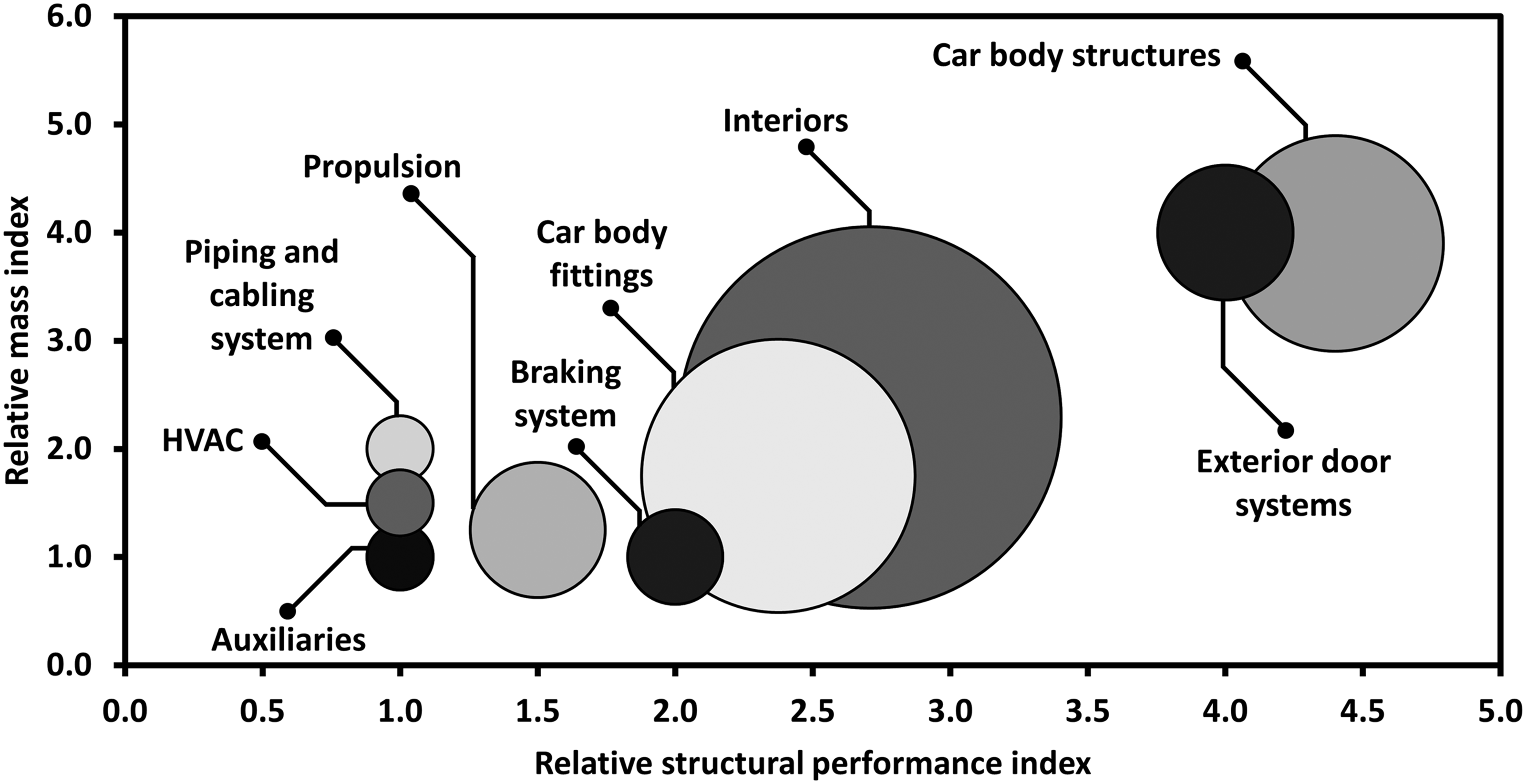
Technically feasible components
During the preliminary component ranking in step one, only 44 components were determined to be technically feasible and improved by manufacture using composite materials. The component categories are shown in Figure 6.
The 44 technically feasible components identified from step one of the selection and ranking methodology grouped into categories shown as ‘bubbles’. The ‘bubble’ size corresponds to the number of components in that group. Where HVAC refers to heating, ventilation and air condition systems.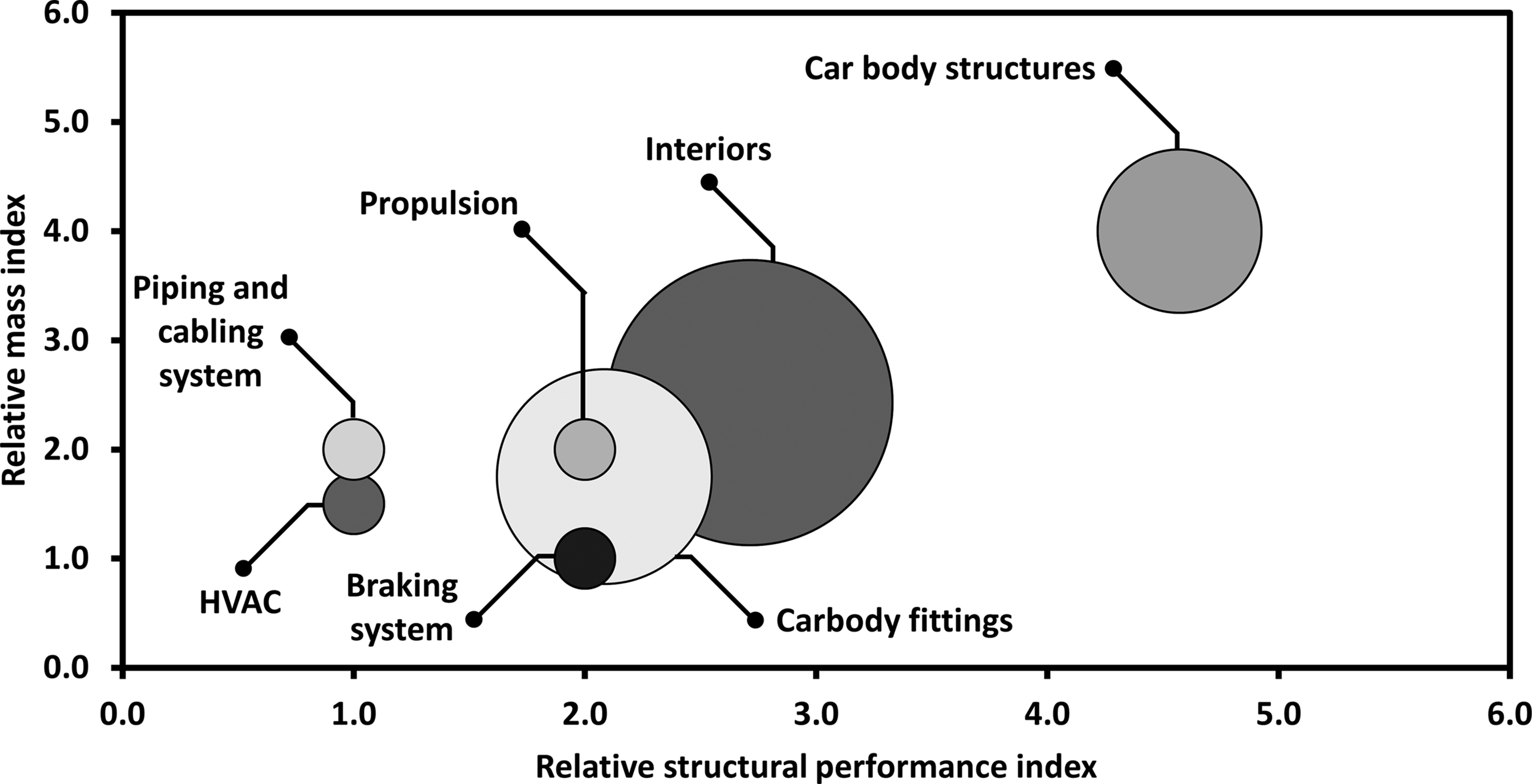
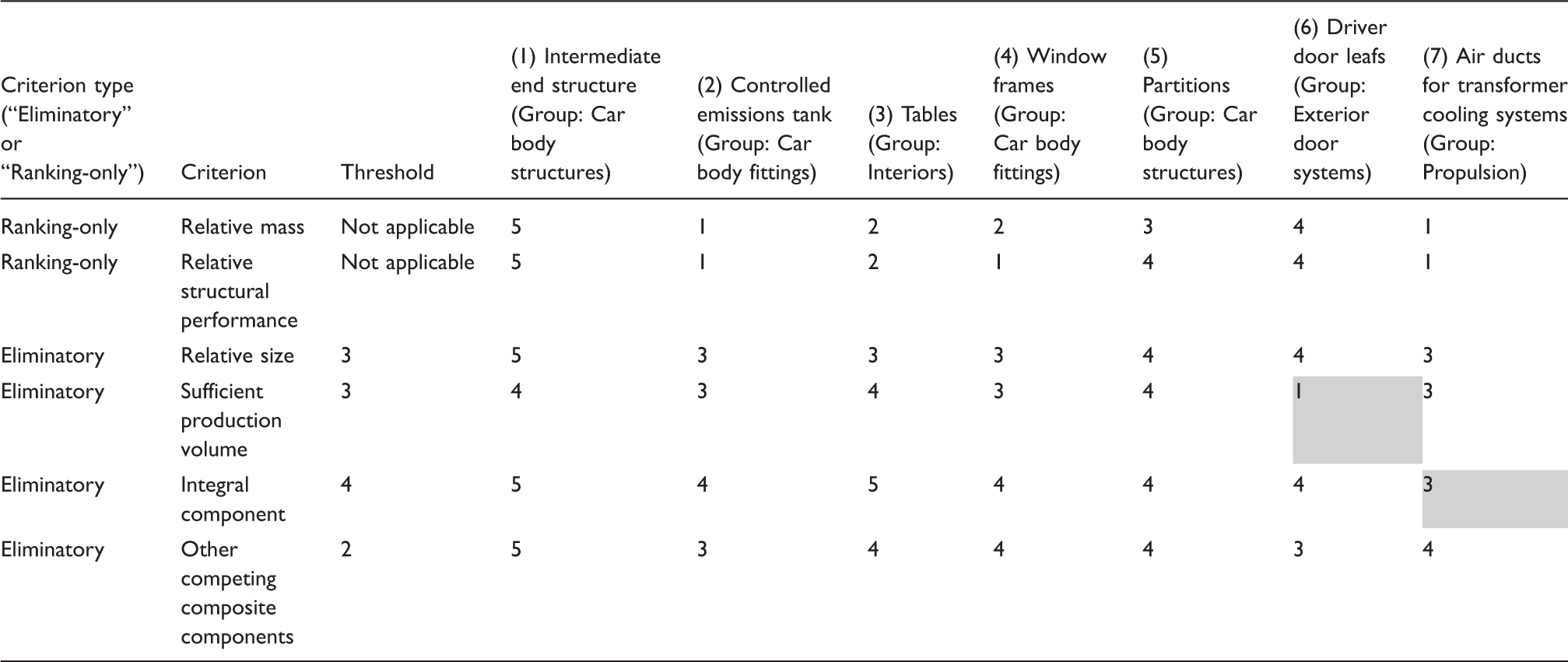
In addition to a reduction of the component pool, the categories have reduced. The auxiliaries and exterior door systems categories were eliminated. The results of the preliminary component ranking (step one) are illustrated in Table 4, for the seven representative components with ranking and eliminatory criteria together with associated thresholds.
From Table 4, two components were eliminated from step one (highlighted in grey as not being technically feasible). Driver door leaves were eliminated due to their low component volume and air ducts for transformer cooling systems were eliminated since they are bespoke components that cannot be further integrated with other assemblies.
Commercially viable components
During the economic potential for a composite component in step two, only 16 components were determined as having the potential to be commercially feasible either today or at some point in the future. The component categories are shown in Figure 7.
The 16 commercially viable components identified from step two of the selection and ranking methodology grouped into categories shown as ‘bubbles’. The ‘bubble’ size corresponds to the number of components in that group. Where CET refers to controlled emissions tanks.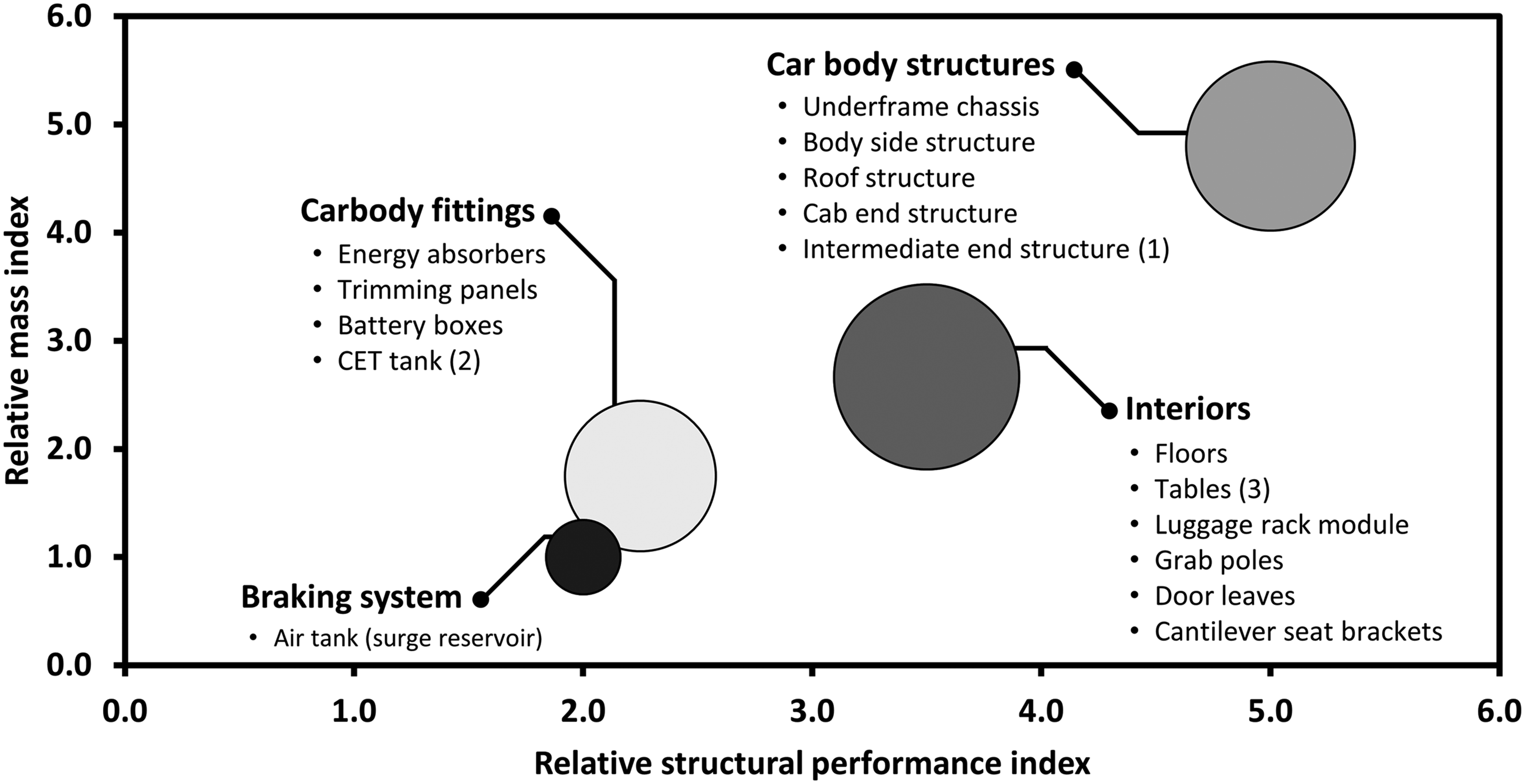
The components within the HVAC, piping and cabling system and propulsion categories were eliminated. The remaining 16 commercially viable components are encompassed within the braking system, car body fittings, interior and car body structures categories.
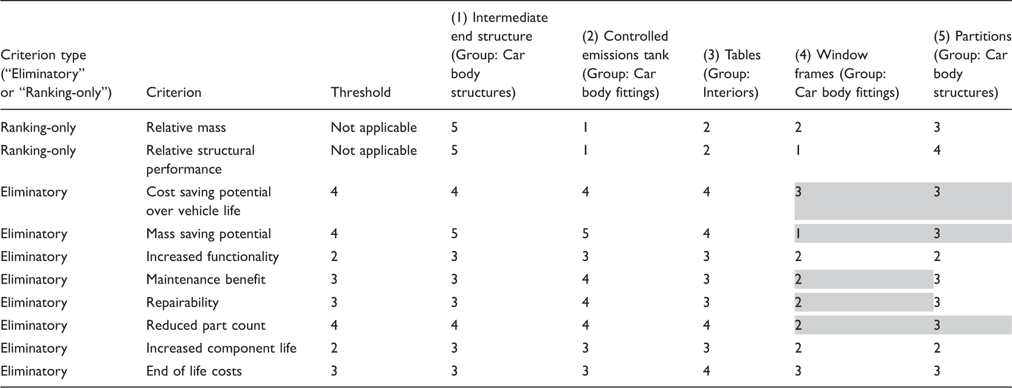
The results of the economic potential of a composite component (step two) are shown in Table 5, for the representative set of components with ranking and eliminatory criteria together with associated thresholds.
From Table 5, two components were eliminated from step two (highlighted in grey as not being commercially feasible): window frames and partitions. The low structural requirements for window frames permit them to be low mass as metallic components, negating the benefit of composite substitution. The elimination of partitions is less obvious as these are large semi-structural components. However, unique geometry and potentially the need for handedness increase tooling costs making them impractical commercially.
Demonstrator components
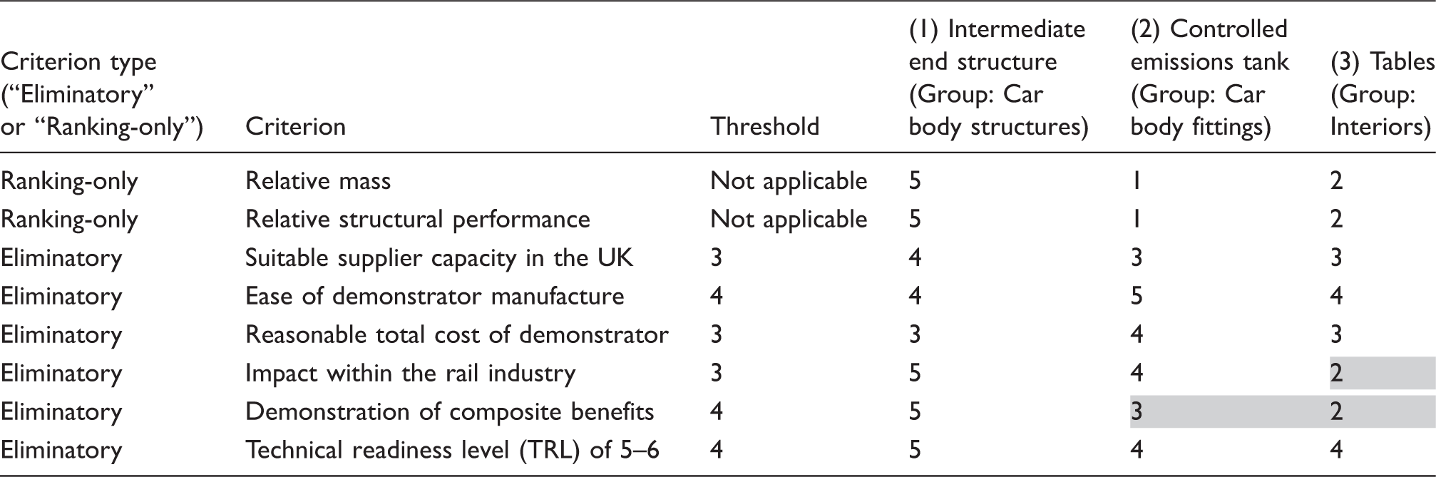
The results of the composite component evaluation of the commercially viable components (step three) are illustrated in Table 6 for a representative set of components with ranking and eliminatory criteria together with associated thresholds.
Both controlled emissions tanks and interior tables have been eliminated during step three of the methodology. While it is beneficial to manufacture controlled emission tanks using composites to take advantage of superior corrosion resistance and insulation properties, the mass advantage is minimal compared to a metallic version. Interior tables are potentially good demonstrators; however, they do not clearly showcase the advantages of composites in terms of complex geometry.
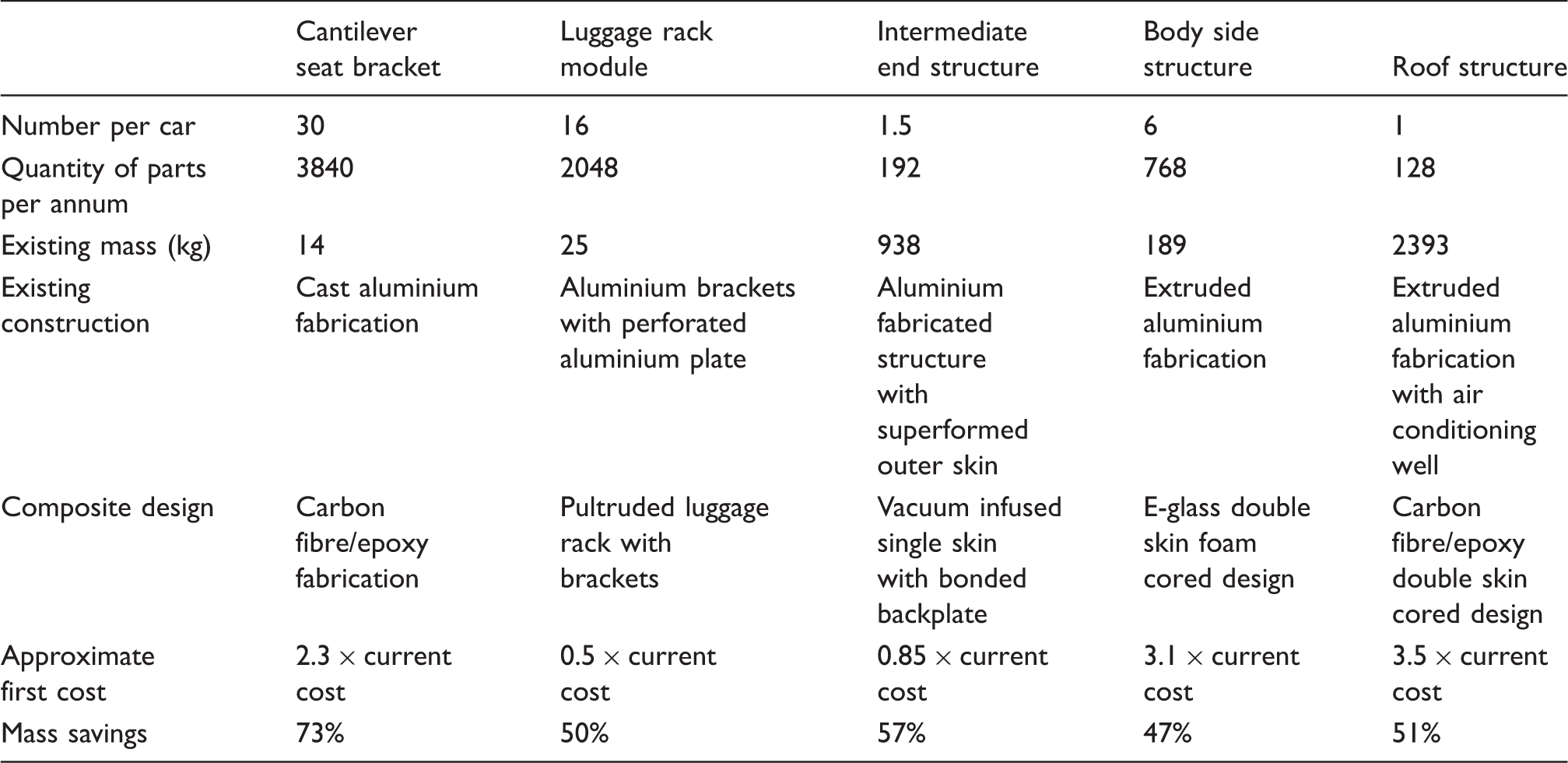
Demonstrator component attributes based on an EMU passenger rail vehicle.
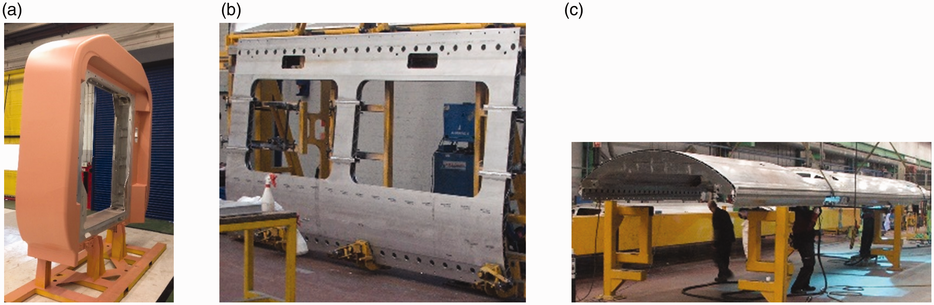
The chosen demonstrator parts were grouped into interior structural components (cantilever seat bracket and luggage rack module) – see Figure 8, and car body structural components (intermediate end structure, body side structure and roof structure) – see Figure 9.
Interior structural demonstrator components: (a) cantilever seat bracket and (b) luggage rack module (source: Bombardier Transportation). Car body structural demonstrator components: (a) intermediate end structure, (b) body side structure and (c) roof structure (source: Bombardier Transportation).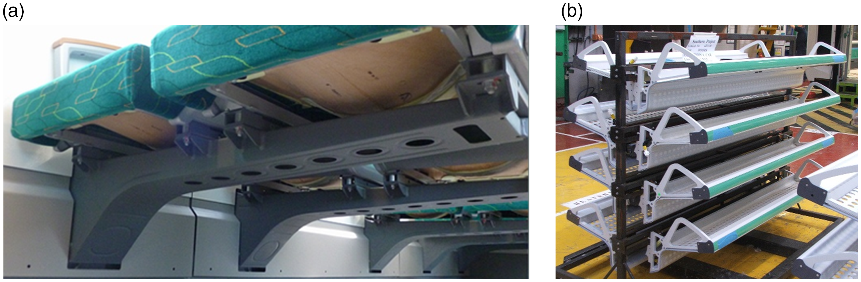
Out of the five demonstrator components, cantilevered seat brackets showed the greatest potential for mass savings of approximately 73% when redesigned in composites. However, the relative first cost of the redesigned component is 130% greater than the current design. The luggage rack module and intermediate end structure components were deemed to be the two most suitable demonstrators for a composite redesign based on mass savings and approximate first cost currently. A composite luggage rack module is estimated to cost 50% less and offer 50% mass savings when compared to the current metallic version. Removal of mass at cantrail level is effective in reducing the centre of mass of the car body and improving dynamic stability. Similarly, a composite intermediate end is estimated to cost 15% less and offer 57% mass savings when compared to the current metallic version. While the number of components per car may vary for different types of rolling stock, all five demonstrator components selected were both technically and commercially viable candidates for lightweighting in rail vehicles by composite design. However, due to the significant mass contribution of the metallic car body structural components to the total vehicle mass (as seen in Table 7), these are considered as the most optimal components for composite lightweighting of the sprung mass of rail vehicles.
Conclusions
This paper has identified key components for lightweighting of a rail vehicle. To achieve this, a methodology was proposed, which was developed as part of the ACIS project. The vehicle audit was undertaken on a Bombardier Electrostar (EMU passenger train) to establish those metallic components suitable for redesigning using FRP composites according to an overarching motivation for vehicle lightweighting in areas demanding high structural performance.
The selection and ranking methodology was developed to evaluate vehicle components consisting of three main steps: (1) Preliminary component ranking, (2) Economic potential for a composite component and (3) Composite component evaluation. The methodology relied upon criteria derived by the rail industry to assess the components through each step to determine the technically feasibility, commercially viability and suitability as demonstrator components.
From the audit, five demonstrator components – a cantilevered seat bracket, luggage rack module, intermediate end structure, body side structure and roof structure, were identified by the consortium using the methodology. These are components that the consortium believes to be the most suitable to demonstrate the benefit of a composite replacement in terms of integration potential, lightweighting benefits and commercial viability.
However, in terms of maximum lightweighting of the sprung mass of rail vehicles, car body structural components (intermediate end, body side and roof structure) were determined to be the most optimal components to replace in composites. It was estimated that a composite redesign of these components would result in a mass savings of 57% for intermediate end structures, 47% for body side structures and 51% for roof structures.
Declaration of Conflicting Interests
The author(s) declared no potential conflicts of interest with respect to the research, authorship, and/or publication of this article.
Funding
The author(s) disclosed receipt of the following financial support for the research, authorship, and/or publication of this article: The rail vehicle audit and methodology was developed as part of the ACIS (Advanced Composite Integrated Structure) project, funded by the Rail Safety and Standards Board, UK [Grant number: RSSB/13/EIT/1744]. The author would like to acknowledge the funding support of the Engineering and Physical Sciences Research Council through the: “EPSRC Future Composites Manufacturing Research Hub [Grant number: EP/P006701/1]” and “EPSRC Industrial Doctorate Centre in Composites Manufacture [Grant number: EP/L015102/1]”.