
Abstract
The hybrid flexible risers have a multi-layered structure and use thermoplastic composite for the pressure and tensile armour. In contrast, a conventional flexible riser uses heavier carbon steel as armour which significantly contributes to its weight. For shallow-water applications, the conventional risers are widely used in offshore oil and gas industry due to their corrosion resistance properties and low transportation costs. However, the weight of conventional risers is a key limitation in ultra-deep-water applications. This shortcoming can be addressed by including a lightweight carbon fibre reinforced polymer (CFRP) composite as one of the individual layers. The use of CFRP reduces the effective tension at the hang off point which is a key limitation in extending the range of flexible risers. Here, the dynamic stability and functional load interactions of both risers (viz: a thermoplastic CFRP riser and a conventional flexible riser) at a water depth of 3000 m were studied. A global analysis was performed considering the onerous 1000-year hurricane wave with 100-year currents. The investigation considered ±150 m vessel offsets, three vessel headings (viz: 135, 180, 225°) and three vessel draughts (ballasted, empty, loaded). Additionally, a numerical model with a variable bending stiffness was used to capture the orthotropic material behaviour of a flexible riser. Results showed that the buoyancy requirement and effective tension were 2.1 times greater and 2% higher for the conventional riser compared to its composite counterpart. The most onerous case for a conventional riser was at zero offset whereas for its composite counterpart was at –150 m along the length of a riser. It was observed that the heavier masses of a conventional riser aid in aligning the weight vector with the upward direction of the buoyancy force. Contrarily, the composite risers undergo large displacements leading to misalignments and instability. Furthermore, the observed bending radius of the flexible riser was found to be within the allowable minimum bend radius at the hog bend location.
Introduction
The subsea engineering of oil and gas production and their transportation is a growing field. 1 They are broadly divided into shallow and deep-water types. The infrastructure and oil extraction in shallow waters are simpler. However, increasing number of explorations are taking place in deep-water environments due to the depletion of shallow water oil fields. A great many oil reserves are in high pressure environments at great sea-depths. Oil exploration at great depths is an expensive and high-risk operation. The extraction process often leads to increased heating and surface oil seeps which pose a challenge to the environment. Subsea fluid transport requires specialised risers which provide the connection between the seabed and the facilities above the sea level. The risers act as conduits to transfer oil and gas from the seafloor to the collection at the top, as shown by schematic in Figure 1(a). The flexible risers can be categorised as conventional and hybrid types which are made of multiple layers of polymers and metal alloys. The metal alloys can be chosen according to strength required. Some nanocomposite metals can be used to increase the properties beyond the conventionally available range.2,3These risers have a low relative bending to axial stiffness ratio. Therefore, they are quickly becoming the standard within the oil and gas industry. These are referred to as flexible risers and utilise a multi-layered design to achieve high levels of flexibility. 4 These riser pipes have layers of high-strength carbon steel wires that are wound in opposed directions, and these designs are evolving. There is a need to design them to meet all possible realms of failures in under deep-water environment. The major challenges are high-pressure applications at elevated temperatures. The combined design pressure and temperature are critical for fatigue life. The riser pipes are susceptible to failure through a variety of different loadings. They can burst and buckle under both inner and outer pressures, tensile, bending, torsional loads and their combinations. 5 A hybrid riser can take stresses well above a traditional high-strength steel. Designing the riser configuration in ultra-deep water environments presents a variety of challenges. 6 The static and operational loads on risers increase significantly at great depths leading to the risk of structural collapse. Thus, there is a need for new technologies, designs, and materials. The flexible risers combine traditional metallic materials with reinforced layers of thermoplastic carbon fibre composites. This combination with the composite material would tackle the major issue of self-weight, however, it amplifies the dynamic response due to bubbles in the flow.7,8 The new composite technologies allow weight to be reduced by at least a third. Thus, the composite designs can be tailored even to a high-pressure environment, better than the high-grade steel designs currently operating. In these risers, a composite metal bonding layer replaces a metal layer with a bonded composite hoop layer. The conventional flexible pipe structure is comprised of a series of functionalised layers of polymers and metals. Due to the metallic reinforcement, the weight per unit length of conventional riser pipes is much higher. This is a challenge as it sometimes exceeds the design requirements for the critical top tension in the deep waters (>2000 m). All metallic sections, especially the heavier carcass layer contribute to the axial load. There are trade-offs between thickness and axial load contributions. Thick layers have a better ability to withstand the external hydrostatic pressures at the same time they also produce greater axial load leading to the increase in the unit weight of the conventional riser pipe. To reduce the weight of the riser per meter, a hybrid design is proposed where the metallic layer is replaced with a bonded thermoplastic carbon fibre composite.
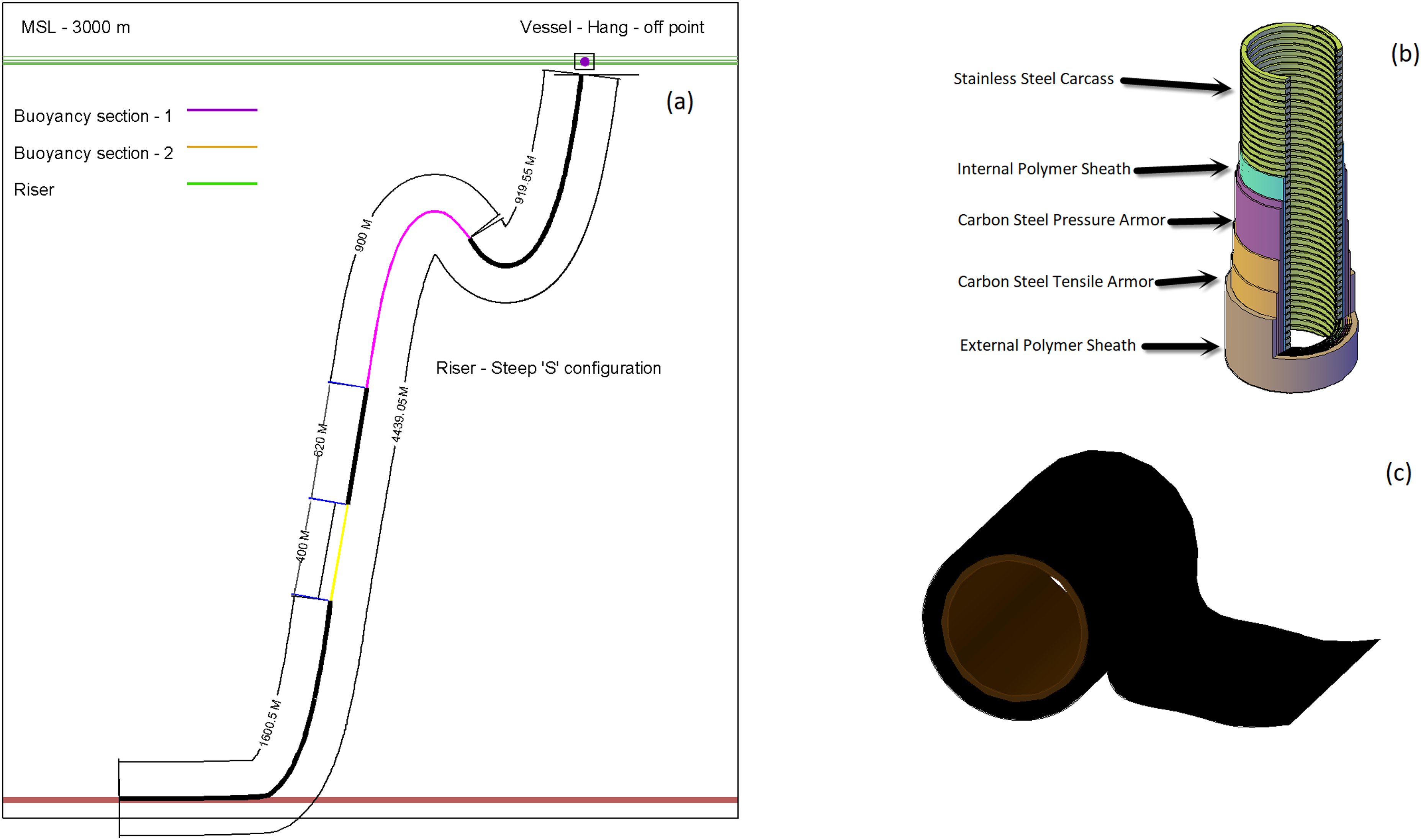
(a) The schematic representation of a riser system in seawater (b) the cross section of a typical conventional flexible riser with multiple layers bonded together (c) the pressure armour made of tape-winded composite carbon fibre reinforced thermoplastic.
The innovating new hybrid riser designs have inner polymer liner made of polyvinylidene fluoride (PVDF) which is tough and wear resistant.9,10 The composite pipe is made via winding the carbon fibre reinforced polymer (CFRP) unidirectional tape around the rigid PVDF pipe. The strong bonding between each layer of the tapes is ensured by applying pressure and heat via hot gas or infrared laser. The unbonded hybrid flexible riser combines low bending stiffness with high axial tensile stiffness where each layer has its own role to withstand tensile, hoop and bending stresses due to internal and external pressures. This allows independent movement of each composite layer and ultimately helps to increase fatigue life compared to a traditional steel catenary. The CFRP composite pressure armour adds complexity to its mechanical behaviour due to reduced weight, increased axial and bending stiffness. The riser construction involves combining multiple layers of composite and metallic wire components into a single construction. These layers interact with each other due to inherent slippage under combined loads of bending, axial and shear. 11 The metal pressure armour wires provide a degree of resistance to axial load and hoop stresses due to internal pressure. The metallic wire under bending stress remains intact however it starts sliding along the geodesic lines above a critical bending stress limit resulting in a nonlinear bending moment. The addition of the CFRP pressure armour further increases the complexity as its cross-section will transform from circular to elliptic under increased bending stress. This leads to ovalisation of the cross-section and would strain the outer layer by 2.5%, which is almost near the maximum limit. Furthermore, the unbonded flexible riser in sea behaves differently compared to the conventional risers containing steel pressure armour.12,13 It is useful to develop a methodology to increase damage tolerance to improve the composite armour life and therefore, increasing overall life. 14
In this work, the performance of a hybrid riser is compared with a conventional unbonded flexible riser pipe at a water depth of 3000 m. Both riser types are normally used for transferring oil and hydrocarbons onboard a floating production storage and offloading (FPSO) unit. An FPSO is a floating and storage facility for extraction and processing of hydrocarbons, including oil from seabed. A numerical analysis for configuration and optimisation was included to keep the effective tension, shear load and compressive loads within the allowable limits. The tension-angle of envelope and the bend stiffener performances were also analysed. The degree of nonlinearity created by wind, waves and currents were also considered. Using the dynamic FE method, a frequency domain analysis was performed. Hitherto, the performances of both conventional and composite risers have never been compared for their strength and stability in deep water environments with a combination of loads. Although, the lightweight hybrid risers have the potential to reduce the effective tension at the same time can increase instability which is investigated here. This work highlights the effect of adding composite pressure armour which aids in the development of hybrid risers design in deep water environment.
Problem statement
The aim of this study is to compare the dynamic stability of a composite riser with a heavier conventional counterpart at an operational water depth of 3000 m. Specifically, to identify the buoyancy requirements and maximum effective axial tension for both types of risers. The analysis applied a 1000-year hurricane wave with 100-year currents for the stability management and functional load interactions. The load cases were built with two different vessel offsets and three vessel headings. All the analyses were repeated considering two different sea-water densities and vessel draughts.
Analysis consideration
The analyses were performed using the following considerations:
The material models considered the slippage of the outer sheath, composite and tensile layers which is realistic depiction of a flexible layer model.
11
The designed pitch, diameter and height of buoys were kept at 14, 2.1 and 5 m respectively for risers of density 4500.0 kg/m3.
15
The volume fraction of carbon fibre, tendons and their lay angles were considered to calculate the equivalent stiffness. The overall friction coefficient of 0.4 was used to determine the shear capacity, stress–strain relation of risers. The differential pressure between internal and external sides of riser was the determining factor responsible for the slippage of the layers. No weight or other ancillary equipment were considered in the analyses to restrain the risers at the seabed. A steep wave configuration with multiple sections was used in buoyancy calculations. The values calculated using these considerations were ± 5% of published values.
15
Riser analysis input data
The riser system design schematic is shown in Figure 1(a), this configuration was used in dynamic finite element analysis and for placing the buoyancy section of required length. The hybrid design flexible riser was of 203.2 mm outer diameter (OD), its allowable axial tension and compression limits were 5550 and 20 kN respectively. 14 The allowable minimum bending radius was 4.06 m at a maximum shear stress limit of 23 MPa. 16 The overall minimum bending radius was estimated based on 3% of maximum pipe strain. In Figure 1(b), the typical cross section (image is redrawn from Karegar 17 ) of a flexible riser pipe is shown. These are constructed with multiple layers of polymers and high strength metal alloys. The hybrid type risers are made of tape winded composite CFRP as shown in Figure 1(c).
Stiffness and composite properties
The equivalent axial and bending stiffnesses for the hybrid design flexible riser pipe were taken as 220.0 and 170.0 kN/m respectively. The overall bending stiffness is an assembled combination of each individual layer. The reinforcing efficiency and a rule of mixture were applied for calculations. 18 The dimensions and material specifications for each layer of the hybrid design flexible pipe were taken from the work of Kalman and Belcher. 19 The analyses considered load cases involving scenarios of both empty and seawater filled pipes. The maximum external and internal pressures of 40.0 and 30.0 MPa were considered. As mooring lines do not make marked difference in lateral movement of FPSO, they were not modelled in the global analysis. The response amplitude operator (RAO) data from the work of Brown 18 was used. The composite section consists of layers of thin tapes made of carbon fibres embedded in thermoplastic polymer matrix. The carbon fibre lay angle of 45° and its volume fraction were considered.
The orthotropic material properties for the composite section were analysed in cylindrical coordinate systems. The elastic modulus in axial direction was 700.0 MPa and in the hoop direction 94,800.0 MPa, respectively. 20 The Poisson's ratios ν12, ν13, ν23 values considered were 0.0023, 0.96 and 0.315, respectively. 20 The modulus of rigidity for G12 and G23 were 180.0 and 910.0 MPa, respectively. 20 The plane stress models were used for the calculations of the variable bending moment. The hybrid design of the flexible pipe uses a composite in place of a metallic hoop layer. The configuration uses bending stiffener to distribute the bending moment more widely along the line to prevent excess bending curvature. The bending stress–strain relationship of a stiffener is shown in Figure 2(a). It has a taper with a constant inner and variable OD in relation to its arc length as shown in Figure 2(b).
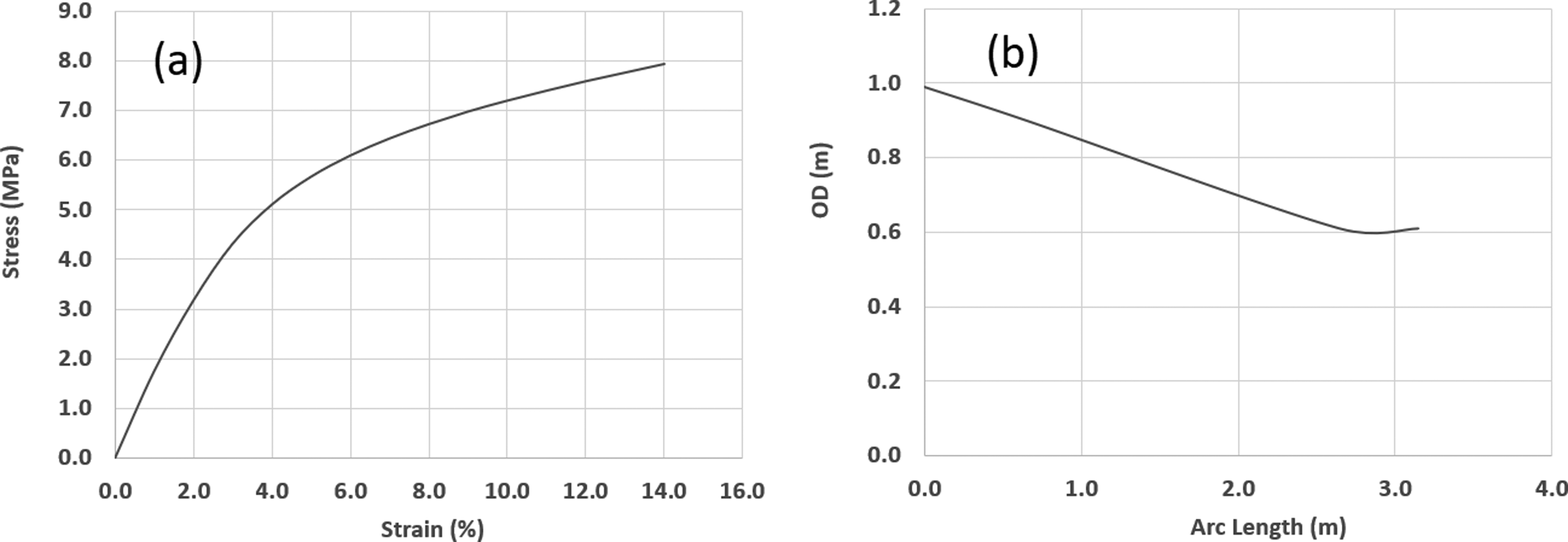
(a) Stress–strain relationship of the bending stiffener and (b) outer diameter (OD) variation with the arc length.
Vessel and environmental data
The mean sea level was assumed to be 3000 m. The most conservative 1000-year hurricane wave and 100-year current data were used. The Dean wave theory of fifth order was used in global analysis. The significant wave height varied between 15.15 and 17.7 m, and the associated period to maximum wave height (Tass) varied between 14 and 15.5 s. The FPSO vessel of mass 9.0 tonne and dimensions 103 × 45 × 20 m was used for the global analysis. The RAO data 18 was used for 90°–180° vessel motion at 45° increments. An illustration of the wave motion of the vessel is shown in the Figure 3(a). The longitudinal and transverse friction coefficients of 0.47 and 0.25 were used to capture the interaction of the riser with seabed. Additionally, a seabed with normal stiffness 112 kN/m was modelled as a slope of gradient 0.286° in −73.67° direction. The standard values of 0.7, 1.3 and 1.05 were used for the smooth, buoyant and bend stiffener coefficients. The standard drag coefficient (Cd) from the work of Brown 18 was used and the inertia coefficient (Cm) was assumed as 1.0. The soil supporting the riser was modelled as nonlinear springs in the structural analysis. The 100-year period of sea-water extreme current profile with sea-water depth is shown in Figure 3(b).
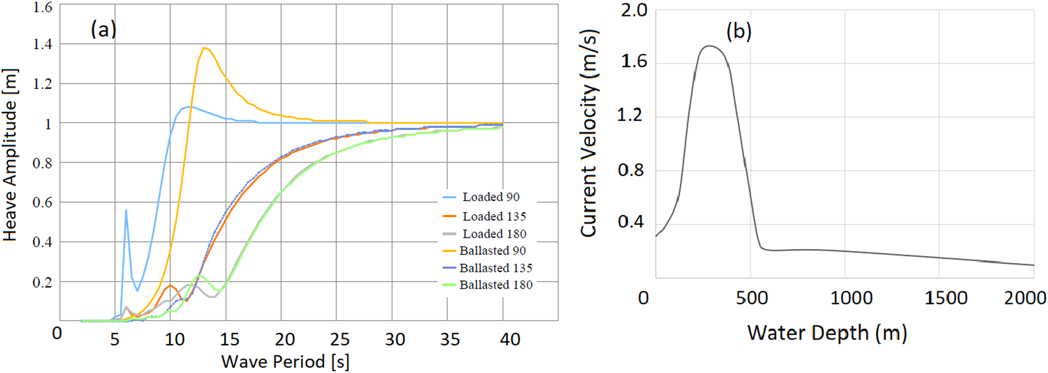
(a) Heave response amplitude operator (RAO) of FPSO and (b) the sea extreme current profile.
Numerical analysis methodology
The global analysis of the riser system was performed in three stages 21 considering the global position of risers in the sea location. The nonlinear dynamics at local level analysed using cross section of all riser layers. Initially, a preliminary static analysis was performed to identify a suitable riser system. This is followed by dynamic and extreme load cycle analyses using the regular and irregular wave loads, and environmental conditions. Finally, a fatigue analysis was performed considering the operational and functional loads on the system during the planned operational life. The modelling tools OrcaFlex 22 and Mathcad 23 were employed. The smeared buoyancy was used throughout the analysis. The internal surface temperature of a riser will fluctuate during the operational life 5 therefore a conservative estimate was made for the surface temperatures. The orthotropic material properties were assigned to carcass layer. It is assumed that the axial stiffness is insignificant in relation to hoop direction for carcass layer. The outer sheath layer is modelled as an isotropic material. 5 A multi-linear model was adapted for calculating the bending moment to curvature relationship for armour layer. The composite layer was modelled as an anisotropic material. The anti-wear tape and tensile armour were modelled as steel (E = 200 GPa, ν = 0.3). The PVDF (E = 3.0 MPa, ν = 0.31) material was assigned to inner sheath and polymer (E = 320 MPa, ν = 0.38) for the outer. The carcass was assigned with anisotropic material properties (Ex = 95.4 GPa, Ey = 150 GPa, Ez = 100 kPa, νxy = 0.31, νyz = 0.39, νxz = 0.006, Gxy = 36.5 GPa, Gyz = 54.0 GPa, Gxz = 50.0 GPa 20 ). The composite properties (Ex = 75 GPa, Ey = 600 MPa, Ez = 600 MPa, νxy = 0.124, νyz = 0.55, νxz = 0.22, Gxy = 190.0 MPa, Gyz = 100.0 MPa, Gxz = 610.0 MPa) were assigned to pressure armour. 15 The contact points on riser were defined as bonded or frictional. The contact relationship was set for pairs of external carcass layer and inner sheath, similarly, between inner sheath and pressure armour and anti-wear tape layer and outer sheath. All analyses were repeated with both bonded and frictional contact configurations. The augmented Lagrange formulation was adopted. A direct solver type was used with the stiffness was made to update at each increment of numerical iteration. One end of the riser was fixed in all directions. The opposite end was set unconstrained in radial and transverse directions. The forces of actual load experienced in sea conditions were applied as a displacement in the axial direction. Along with these constraints the subsea operational loads were applied. Internal and external pressures of maximum 32 and 42 MPa as a function of time were applied. The net contribution of stiffness from each layer is summed up to compute the multi-linear bending characteristics.
Static analysis
A total of six load cases were simulated in static state which meets the required limits for minimum bend radius (MBR), effective tension, compression and shear forces. All load cases were simulated initially under ballasted draught condition and later repeated with actual loading. The simulations used a content density of 1025 kg/m3. All simulations considered three vessel headings (−150, 0.0 and 150 m). Three main loading components (viz: volume, specified and currents) on risers were considered. The static equilibrium was evaluated based on riser and its components mass, sea-water density, buoyancy and transported fluid properties. The riser undergoes into a pre-bent state due to bending loads which is based on a bending moment to curvature relation as shown in Figure 4(a). A peak load was witnessed after a time of 0.1 s before the pressure was applied to the tensile armour layers. An acceptable deformation of 19.9 mm was predicted in the radial direction. The forces were evaluated based on the equilibrium and effective tension and weights in immersed water conditions. The equations were developed based on the combined effects of tension, internal and external hydrostatic pressures. The FE models examined in this paper used the equivalent effective parameters for all the loads.
14
In Figure 4(b), illustrations of the force balance and equilibrium of curved riser section is presented (images are redrawn from reference
14
). It was assumed that the wave loading acts in line with the hog bend of the vessel as shown in Figure 4(c). The formulas for the effective weight and tension are expressed in equations (1) and (2).


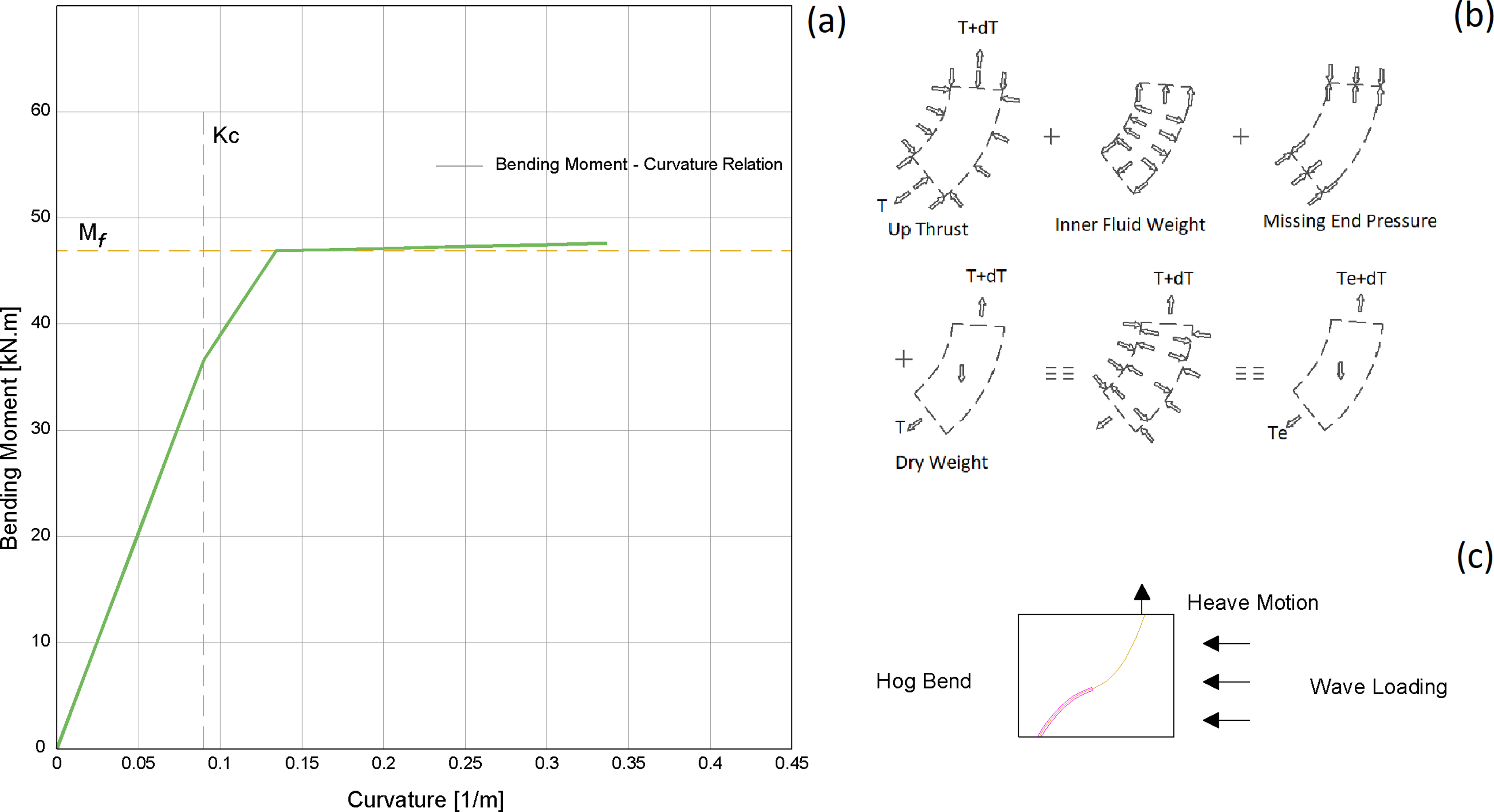
(a) A multilinear bending moment to curvature relation for composite riser pipe (b) illustrations of effective weights and tensions and (c) an illustration of wave loading acting on the Hog Bend of riser.
During the actual installation phase of the riser platforms, pulling forces are normally applied. This is performed in the installation to keep the riser in tension and to avoid buckling of the lower section. In the FE model, the equivalent edge-loads were applied on the top section of the riser. In the static analysis, equivalent forces were applied on risers to mimic this condition. Finally, all the static and current loads were assigned to the system. These also include the forces of current loads. To determine the static equilibrium conditions, it is important to determine the forces acting of the riser generated by the sea-water current.
The steady current induces drag forces on the riser and buoyancy modules. The relative magnitude of these forces in comparison with volume forces were evaluated for all configurations. The static equilibrium configuration was defined in a series of iterative stages from the initial point of the riser system. The vessel and buoys positions were defined by the initial data at the start of the calculation. It was assumed that the risers were fixed at their ends for the equilibrium configuration. The out of balance loads acting on each body were then calculated and the new position for the body was defined. The calculations were repeated until the out of balance loads on riser body were equal to zero within the specified tolerance. The equilibrium system configuration was then used as starting configuration for the dynamic analysis. The riser system was analysed under all functional loading. The analysis allowed to determine the lengths of the flexible riser considering vessel position to touchdown point and the riser hang-off angle. A correct angle was chosen to minimise the tension along the river and buoyancy requirements. A refinement of the configuration was carried out to find correct buoyancy required to bring key parameters such as effective tension, minimum bending radius, shear and bending stresses under allowable limit.
Dynamic analysis
All load cases were subjected to numerical analysis under dynamic conditions (wave, wind, current, vessel movement) to assess the dynamic response due to environmental loads. The buoyancy levels were optimised to reduce the effect of vessel movement on the effective tension and bend radius of riser. A set of load cases were generated for three wave heights (15.4, 17.1 and 17.6 m), three offsets (−150.0, 0.0 and 150.0 m) and three vessel headings (135.0, 180.0 and 225.0°). All analyses were repeated under ballasted as well as loaded vessel conditions. Altogether, 36 configurations of load cases were analysed using a regular wave approach. The frequency and time domain analyses were run on the riser system. The FE models were simulated over a defined period of time to avoid resonance effect in operational conditions at sea. The critical eigen frequencies plausible under natural conditions as well as extreme conditions were examined. The resonance effect has the potential for excess vibrations of the riser system leading to fatigue damage. The floater motions of the riser and station-keeping systems generate a complex dynamic response to the environmental loadings. Therefore, the natural frequencies of the riser and the vortex sheading frequencies were first identified. The frequency domain dynamic analysis is computationally less expensive and is performed for the linear systems.
Using this analysis, a wide different load conditions were analysed. The system of equations for flexible riser was linearised by introducing some degree of approximation. It is assumed that the stiffness, inertia, damping and external forces have linear behaviour at static equilibrium conditions to linearise models. A time domain analysis evaluates non-linarites at each time step and directly updates the dynamic solution. The complete time domain analysis is computationally costly and demands much greater computational time than frequency domain analysis. As such, complete time domain analysis was restricted to only for critical load cases. An overview of the theoretical aspects of the linear and nonlinear solution schemes implemented is presented here. A linear time domain analysis assumes the system matrices to remain constant during the dynamic response calculation. Essentially the dynamic response is calculated as a perturbation of the static condition. The non-linear analysis updates system configuration for each time step during the iterations as per the equation (3). The computation method for non-linear dynamic analysis is based on two solution schemes (viz: explicit and implicit). Both schemes recompute system equations at every time-step increment and allow the full account of all geometric non-linearities of the system.

Results and discussion
The flexible risers are designed for their maximum bending moment, shear force, MBR, Ez angle and effective tension at hand off point. Higher values above critical allowable stresses can lead to failure of the hybrid riser under environmental load. To avoid failure, the riser laying configuration is designed using the FE analysis codes. Various types of configurations (viz: ‘lazy S type’, ‘steep S type’, ‘lazy wave’, ‘pliant wave’ and ‘steep wave’) are proposed to avoid extreme stresses and low fatigue life. In this work, all load cases were analysed with 1000-year hurricane regular wave and 100-year current. The global analysis also considered ± 150 m vessel offsets, three vessel headings, and two vessel draughts for risers with two content densities. The analysis predicted 2.1 times more buoyancy for the conventional riser pipe in comparison to the composite. With this buoyancy, the maximum effective tension along the length of the riser was predicted to be higher for the conventional riser pipe. In a deep-water, the heavier metallic reinforced conventional risers require higher buoyancy. The heavier conventional risers provide more stable configurations compared to a lighter composite. The large mass can withstand greater fluid inertial load with minimum displacement. This helps align the weight vector with the upward direction of the buoyancy force. A larger displacement prompts potential misalignment leading to sideways movement of riser and more instability.
Effective tension and shear forces
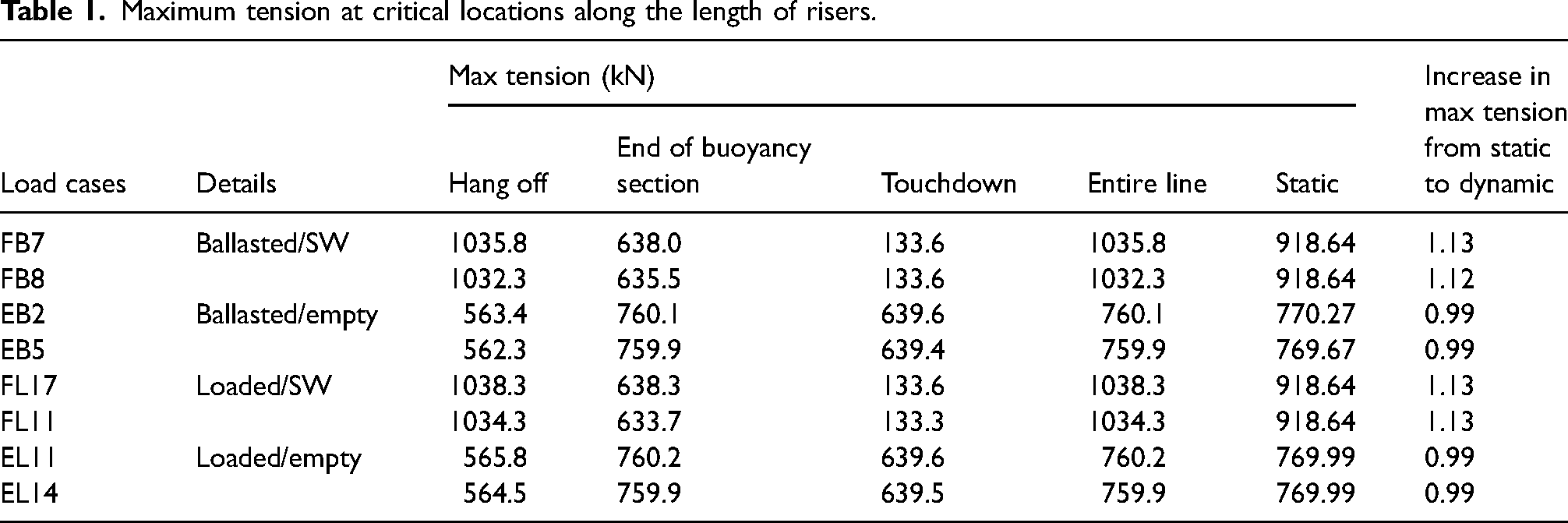
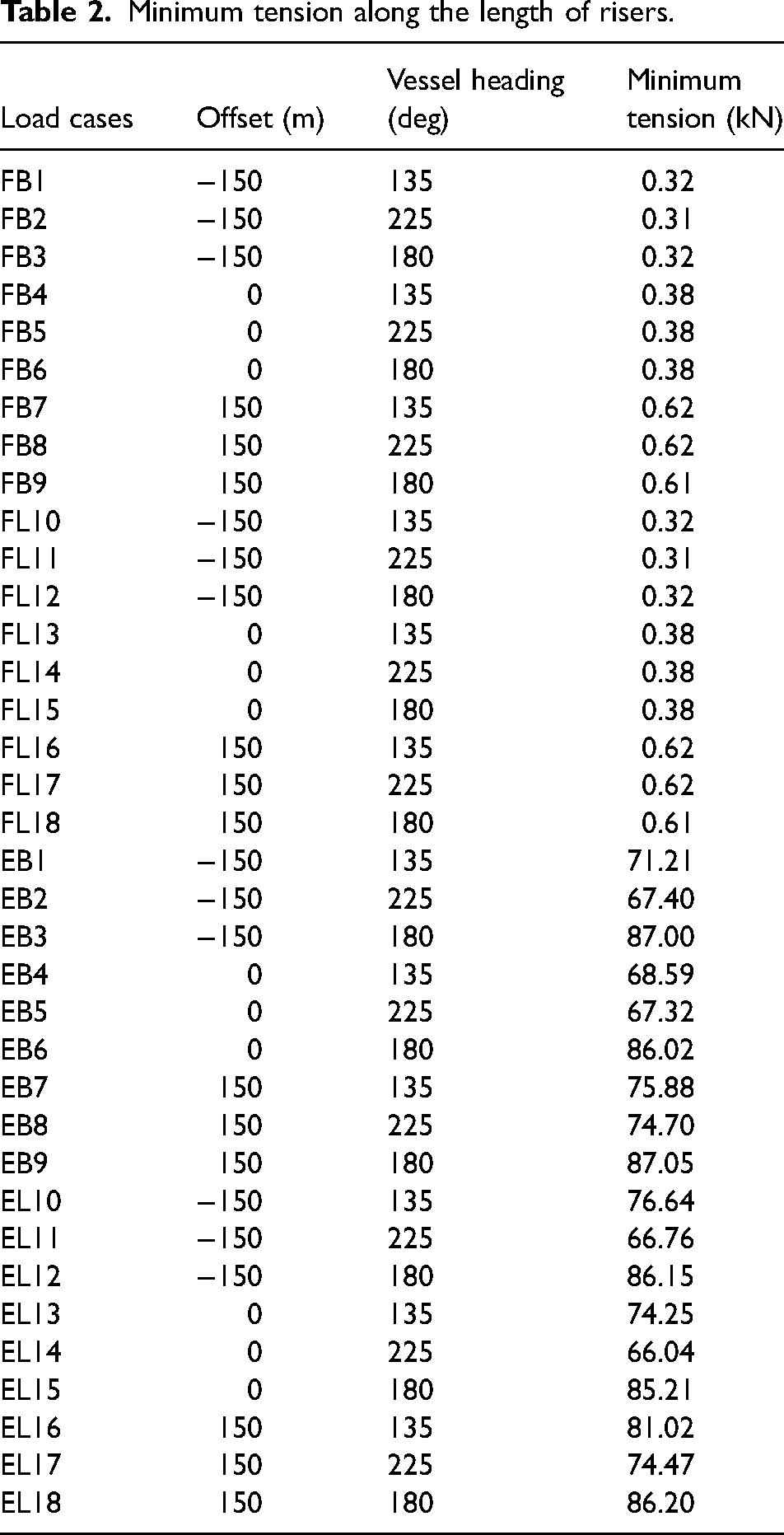
The effective tension is an important parameter in determining the installation and production vessel capacity. A larger size vessel is required if effective tension is higher and vice a versa. A correctly designed configuration with optimised buoyancy can reduce the effective tension to an acceptable design limit. Generally, the effective tension is kept below 1100–1600 kN for 8ʹʹ flexible riser at hand off point, though it is also dependent on the loads and sea environmental conditions. The Table 1 lists the maximum tension for the most onerous two load cases for the four combinations of the vessel draughts. The maximum tensions are recorded at the critical locations of the riser configurations. The Figure 5(a) displays the maximum predicted effective tensions along the length for the seawater flooded and empty risers. Each label on the bar displays the parameters related to the load case. The effective tension was found to be within the acceptable limits of 1.8 kN. The minimum effective tension was predicted for the end of the riser and listed in the Table 2. The positive values of the minimum tension along the entire length of the riser show that the riser was not under compression at the touch down location. If the large weight of the riser is transferred on the section which touches the sea floor, it can buckle under compression resulting into failure. For designing the right riser configuration, it is important to keep the end of riser in tension. The Table 3 lists the maximum shear force at various critical locations along the length of the riser for most two onerous load cases.
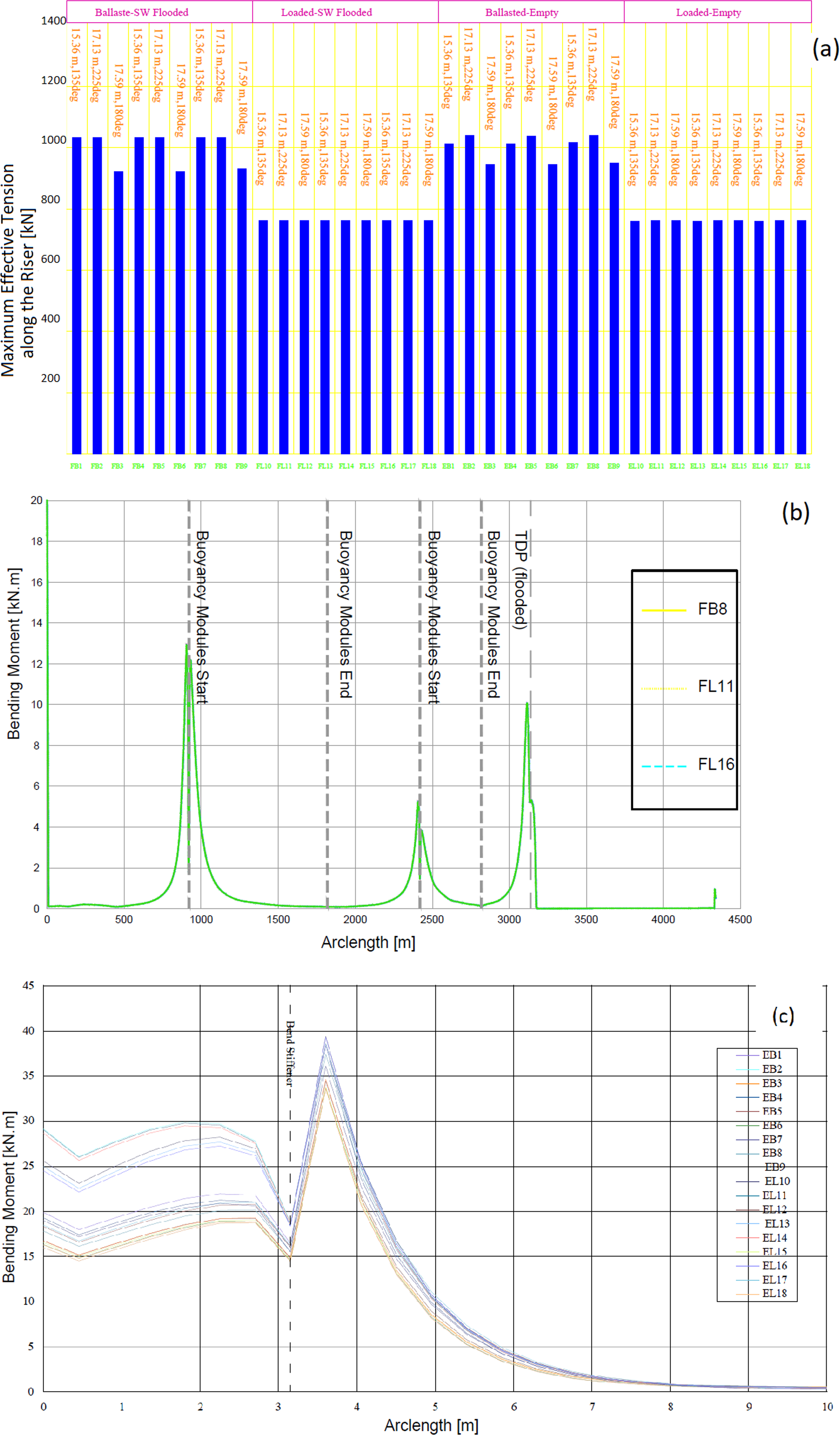
(a) The maximum tension along the length of risers (b) the predicted bending moment along the length of riser (c) the predicted bending moment along the bend stiffener.
Maximum tension at critical locations along the length of risers.
Minimum tension along the length of risers.
Maximum shear load at critical locations along the risers.
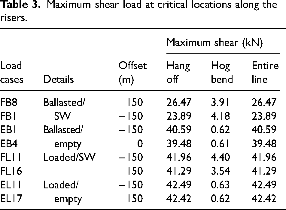
The maximum shear force occurred at hang-off location of empty riser with −150 m offset at 225°, which is expected for riser with a bend stiffener attached at the hang off point. The bend stiffener is normally installed just below the steel end fitting which is connected to FPSO turret. As steel end fitting is significantly stiffer than the flexible riser, a bend stiffener is added to prevent a sudden change in stiffness leading to a significant deformation of the flexible riser. The shear stress was predicted to within allowable limit of the 23.0 MPa.
20
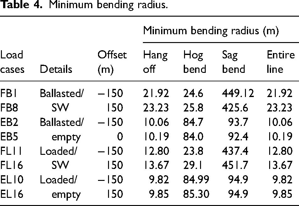
The maximum shear at the sag bend and touch down point was found to be small and within the allowable limit. As seen in Figure 5(a) the effective tension was affected by the vessel motion and vessel heading. The maximum effective tension was with ballasted draughts. It is due to heave amplitude being 1.3 times higher than the loaded draught for 90° (Figure 3(a)). Additionally, the vessel heading of the 225° was found to affect the effective tension more in comparison to other cases examined. As the riser was attached to the vessel, the change of vessel heading from 0° to 225° stretches the riser generating additional effective tension. Another important observation is the effect of environmental load on the effective tension. As seen in Table 3, the effective tension for seawater flooded riser was found to be 1.13 times of static model. The effective tension decreased marginally for empty riser due to dynamic effects. The dynamic motion induced effective tension did not increase. On the contrary, the positive buoyancy reduced the tension marginally. The maximum dynamic bending moments along the length of the seawater flooded riser is shown in Figure 5(b), a value of 16.5 kN-m was at the start of buoyancy module with 150 m offset and 225° vessel heading. Subsequent two peaks are seen at the start and at touchdown points, a maximum bending moment of 30.0 kN-m was within the acceptable limits. The bending moment reaches to a maximum just outside the bending stiffener. For small curvatures, the riser pipe exhibits maximum bending stiffness due to its rigidity. However, when reaches critical curvature Kc, the layer starts to slip leading to decline in bending stiffness. This process continues until full slippage occurs at the corresponding critical moment. The Figure 5(c) displays the maximum predicted dynamic bending moments along the length of the stiffener. The critical curvature can be defined as per the equation (4).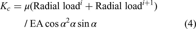
Minimum bending radius.
Tension-angle at hang-off point
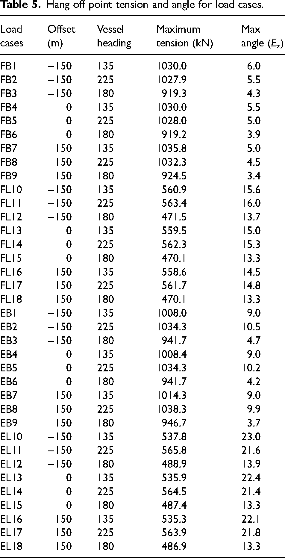
The maximum predicted tension and Ez angle at the hang off point are in the Table 5. These tension values are not necessarily the maximum value along the entire length of the pipe. The effective tension was predicted to be 537.8 kN for the most onerous Ez angle of 23° whereas the maximum Ez angle was found to be 9.9° for most onerous tension of 1038.3 kN. As seen in Tables 1 and 5, for seawater flooded riser, the hang-off point was subjected to a highest tension. The highest tension occurred at hog bend for all risers with no content. In empty riser, the bending due to environmental load at the hog bend generated a larger tension. The weight of content combined with riser contributed to the highest tension at the hang-off for the seawater flooded riser.
Hang off point tension and angle for load cases.
Conclusions
In this work the dynamic stability of a hybrid riser and a heavier conventional flexible riser were examined. The analysis was conducted under sea-water depth of 3000 m considering the slippage of the outer sheath, flexwear, composite and tensile layers. The overall friction coefficient of 0.4 was used to determine the shear capacity, stress–strain relation of the riser pipe. The analysis predicted that the difference in pressure between internal and external layers was responsible for the slippage of layers. The buoyancy required in seawater flooded environment was found to be too high for empty composite riser. Therefore, extra weights or use of a combination of conventional and composite risers should be used to balance the buoyancy forces. It is recommended to use upto 300 m length of the conventional pipe. This is to be attached to the end of composite riser, which is on the seabed. This would restrict the lifting of the empty riser in water. Additional modules are not required to be distributed in many sections. Thus, it is possible to adjust the maximum effective tension along the composite riser below 1038.3 kN. The entire installation setup can be completed with 100 tonne vessels. The following conclusions were reached.
Considering the volume fraction of carbon fibre, tendons and their lay angles, the equivalent stiffness of the composite riser pipe was predicted to be 169.0 kN-m2. The critical curvature of the composite riser was found to be 0.097 rad/m. The corresponding bending radius was found to be 10.3 m. This is within the maximum allowable MBR of 10.7 m at 3% of strain limit. The bending moment was estimated to be 36.6 kN-m which is 12% higher than the reported value in literature. The heavy conventional riser would require approximately twice the buoyancy of the composite to be acceptable. The composite risers are light due to which both the tension and shear stresses were lower. They also exhibited a larger MBR in relation to their conventional metallic counterpart. In seawater flooded environment, the maximum increase in the effective tension were predicted to be 1.28 and 1.13 times more for conventional and composite risers, respectively. The predicted increase in the effective tension for conventional riser was about 2% higher compared to the composite. The most onerous case for conventional riser was at zero offset whereas −150 m for the composite. The MBR occurs at the hog bend and hang-off locations for the composite and conventional risers respectively.
Footnotes
Acknowledgements
The author(s) would like to thank Mr Lakhan Gupta of Krishna Enterprises, Faridabad 121004, India for proofreading the manuscript.
Declaration of conflicting interests
The author(s) declared no potential conflicts of interest with respect to the research, authorship, and/or publication of this article.
Funding
The authors received no financial support for the research, authorship, and/or publication of this article.