
Abstract
Flax fiber-reinforced polymer composites are an interesting alternative to synthetic fiber-reinforced polymer composites for many engineering applications. When machining flax fiber-reinforced composite materials that are by definition heterogeneous, the matrix and the fibers react differently and hence many sorts of damage may occur such as poor surface roughness, delamination, and fluffing. The novelty of the current work lies in identifying the major factors that affect the quality of the milled surface of composites reinforced with flax fibers and provides recommendations and collaborative solutions to the composite machining community. In this study, the impact of cutting conditions (cutting speed, feed rate, and fiber orientation) on the cutting forces and surface roughness during milling of the flax/epoxy composite is investigated. For this purpose, slotting tests are performed on flax fiber-reinforced polymer plates using a carbide end mill tool based on a full factorial design of experiment. Furthermore, a randomization in the order in which experimental runs are done is used to reduce bias by balancing the effect of uncontrolled variables that have not been accounted for in the experimental design. It is concluded that the feed rate has the most influence on the cutting forces and roughness parameters. Moreover, the fibers orientation also has a significant effect on the outputs, and the cutting speed has less effect but it remains significant.
Introduction
Composite materials are ever more being used in a wide range of industries including aeronautics, automotive, and defense sectors. The lightweight is one of the main attractions of composite materials in these sectors. They are 30% lighter than aluminum and 25% lighter than steel. This characteristic is currently considered the best way to achieve fuel efficiency and significant reduction of CO2 emissions for aircrafts,1–3 which meet the environmental objective aimed by the European Union to reduce greenhouse gas emissions by 80 to 95% by 2050. In addition to the high strength, high stiffness, durability, low density, and fatigue corrosion resistance, another beneficial characteristic touted by composite materials is their ability to be molded into a variety of complex shapes, without the need to use high-pressure tools.
Among these composites, Carbon Fiber Reinforced Polymer (CFRP) and Glass Fiber Reinforced Polymer (GFRP) are generally regarded as the workhorse of the industry due to their outstanding material properties.4,5 Sauer et al. 6 estimated that in 2022, the global demand for CFRP is projected to reach 194 kilo tons (kt). Similarly, the industrial demand for GFRP around the world continues to grow. In contrast, the global waste of CFRP is expected to increase gradually to 20 kt annually by 2025 7 plus a close quantity of GFRP. As a result, these endless demands and endless waste lead to many environmental problems such as global climate change, ozone depletion, and global warming.
Therefore, this serious environmental impact has highlighted the urgent need for more industrial-scale solutions to recycle composites waste and reused them in closed loop and cross-sector applications. 8
Nowadays, natural fibers are proposed as the main potential alternative materials to synthetic fibers in the composite industry. They have many benefits such as their high specific properties comparable to those of synthetic materials, their low density and hence lightweight, their availability, their renewability, and biodegradability as well as their flexibility during processing.9–11 These benefits have led to an upsurge in the applications of natural fibers composites in many manufacturing sectors.
Complex composite components are usually processed to near-net shape by molding with advanced techniques. However, for several structural applications, some final cutting processes such as drilling and trimming are still needed to reach the final shape required.
The aerospace industry is one of the largest consumers of composite materials. They are widely used in the manufacture of fuselage panels, wings, interior parts, and more. However, the aerospace industry imposes stringent requirements on its finished components including tight tolerances and exceptional surface finishes. However, machining natural fiber-reinforced composite materials presents a number of problems, such as delamination, poor surface roughness, and fluffing defects associated with the characteristics of the composite material being machined and the cutting parameters.12,13 In this context, several researchers have been interested in improving the quality of machined NFRCs, which will help reduce the cost of production of these materials.14,15
Surface quality is an important requirement for components used in the aerospace and automobile industries. It could influence the dimensional precision, the performance of mechanical pieces, and production costs. 16 Furthermore, most of the aircraft composite parts require high surface quality because they must endure harsh and extreme environmental conditions for a long time. When machining composite materials that are by definition heterogeneous, the matrix and the fibers react differently. 12 One of the first consequences is the possible de-cohesion of the fiber and the matrix. Furthermore, the machinability of fiber-reinforced plastics is strongly influenced by the type of fiber embedded in the composite and by its properties. 17 Indeed, when machining natural fibers composites fluff (uncut fibers) may appear on the machined surface and lead to a poor surface condition and therefore the possible rejection of parts. Despite its importance, there is currently no standardized routine for quality control of machined composite parts, which makes the analyses strongly dependent on the personal expertise and experiences of each end user. Furthermore, the end milling of composite materials remains a marginal operation in the industry and the level of expertise for this type of operation is therefore low. The mastery of this operation is therefore essential in producing high-quality composite parts. Hence, further research in the area of trimming and end milling of natural fiber composite is needed.
In this paper, an experimental approach based on a completely randomized design (CRD) is used to highlight the effect of the cutting conditions on the cutting forces and surface roughness during the slotting process.
Methodology
The resin transfer molding (RTM) process was adopted for the fabrication of the unidirectional flax/epoxy laminated composite plate used in this test (Figure 1) with a volume fraction of 41%. The length, width, and thickness of the obtained plate were 290 mm × 290 mm × 5 mm respectively. The flax fibers were manufactured in the form of tapes by the LINEO Company with a density of 1.45 g/m3, whereas the Marine 820 epoxy resin used as a polymer matrix was provided by ADTECH Plastic Systems Company with a density of 1.11 g/m3.
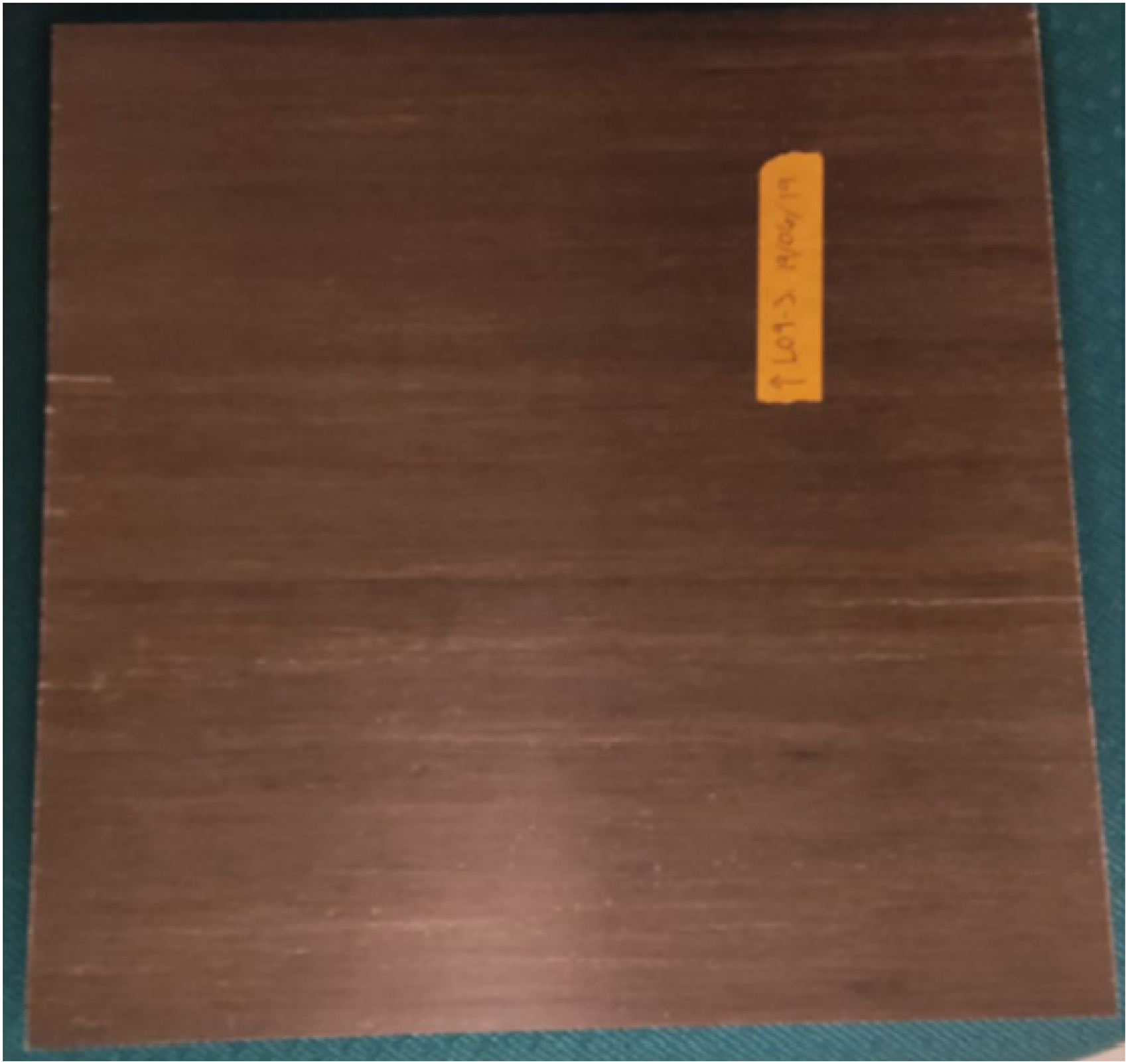
Flax/epoxy composite plate.
The design of experiments (DOEs) is a powerful tool to collect appropriate data and perform an efficient analysis of a process determined by numerous parameters. It allows a significant improvement in the methodology of machining tests. 18 Accordingly, a CRD was used in this work to highlight the effect of the cutting parameters on the surface roughness during the slotting process. As shown in Table 1, different combinations of cutting parameters were tested (3 cutting speeds × 4 feeds × 4 fiber orientations). This leads to a total number of machining combinations of 48 trials (Figure 2).
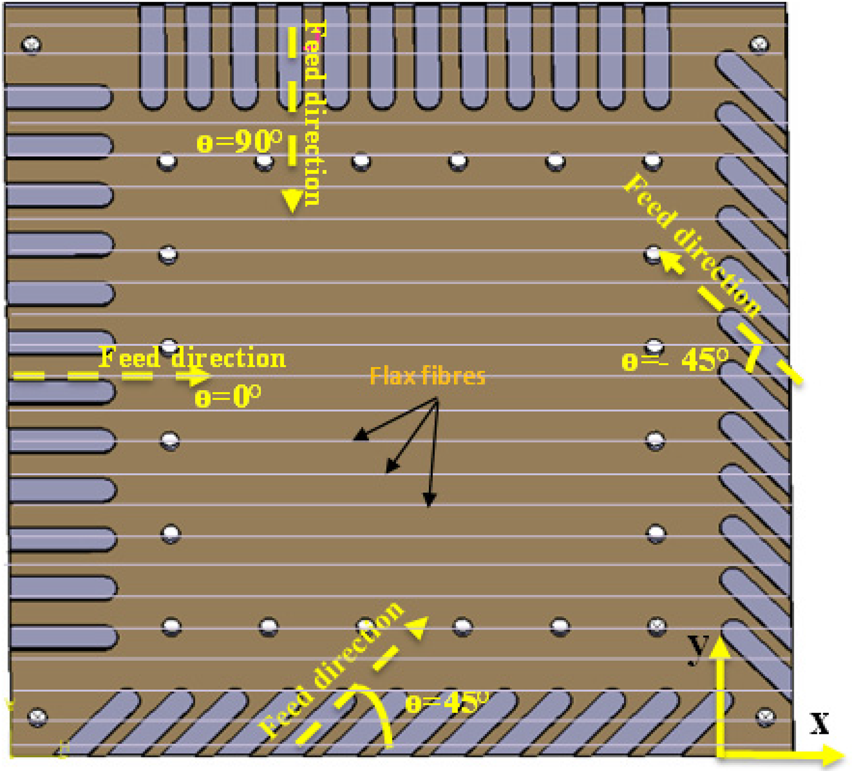
Fibers orientation (θ) with respect to the feed direction.
Design of experiment (DOE) factors for the slotting tests.
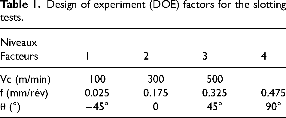
Figure 3 shows that the slotting process is completely randomized. Randomization is used to reduce bias by balancing the effect of uncontrolled variables that have not been accounted for in the experimental design.
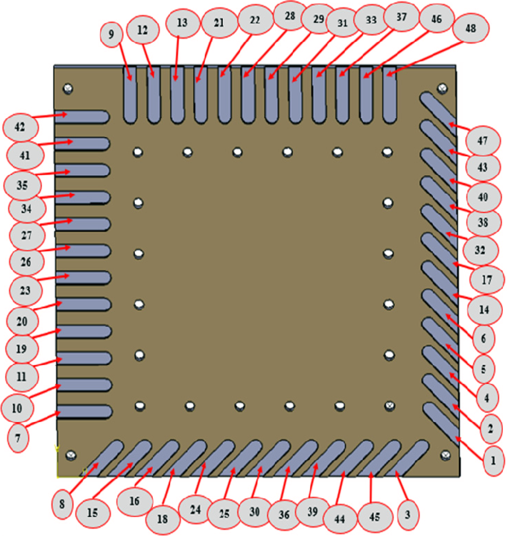
Order of the slotting tests with end mill according to the completely randomized design (CRD).
The slot milling tests were done under dry conditions using a HURON K2X10 three-axis CNC milling machine (Figure 4) equipped with a SIEMENS 840 D controller and a spindle delivering a speed up to 28,000 RPM at 30 kW.
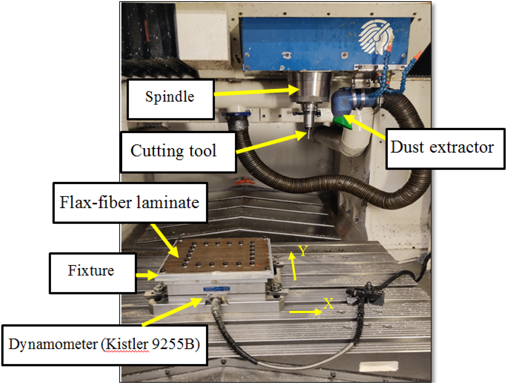
Experimental setup in HURON three-axis machine tool.
An aluminum plating system (Figure 4) was used to secure the laminate. The subassembly (laminate and aluminum plating system) was tightened to a three-axis Kistler 9255B (#3) type dynamometer table. The latter was used to measure the three cutting forces components during tests.
As shown in Figure 5, the cutting tool chosen for this study was a 9.525 mm diameter “AMAMCO” solid carbide end mill with two straight flutes, a 20 μm cutting edge radius, and a 10° helix angle. A dust extraction system was used to vacuum the dust emitted during the slot milling tests.
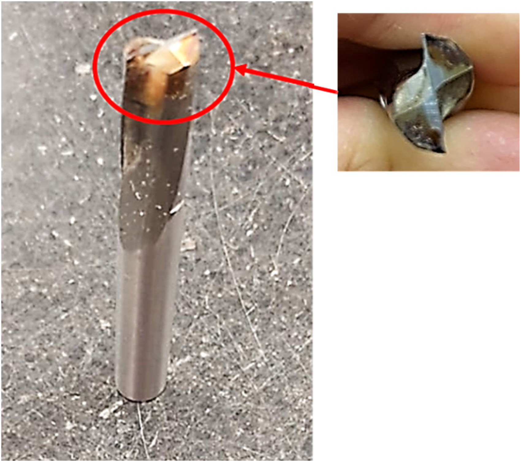
Two straight flutes “AMAMCO” solid carbide end mill.
In this work, the surface roughness was measured using a Mitutoyo Surftest SJ-400 profilometer (Figure 6).
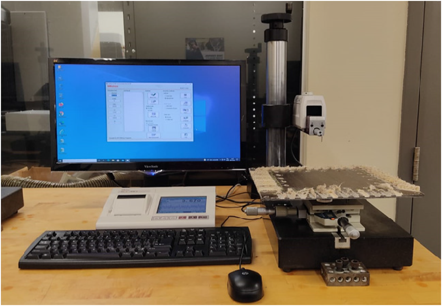
Experimental setup for measuring surface roughness.
Results and discussions
Cutting force plays a vital role in analyzing the machining process of flax fiber-reinforced polymers (FFRPs). In this work, slotting tests were conducted under different cutting conditions according to the order presented in Figure 4, and the cutting forces were simultaneously measured in the x, y, and z directions with a three-axis dynamometer table. The cutting force data were then recorded for further analysis and evaluation.Figure 7 shows, respectively, the evolution of the feed force, the normal force, and the passive force (axial force) as a function of the feed, cutting velocity, and fibers orientation. It can be seen from this figure that all of the cutting force components increase as the feed rate increases which can be accredited to a higher contact area due to increased feed. In other words, during slotting of the composite, the sheared uncut chip thickness increases when feed increases because the composite resists the rupture more and therefore needs larger efforts for chip removal. Hence the cutting force increases as the feed rate increases. On the other hand, the variations of the cutting force are relatively not uniform and depend on fibers orientation when changing the cutting velocity.
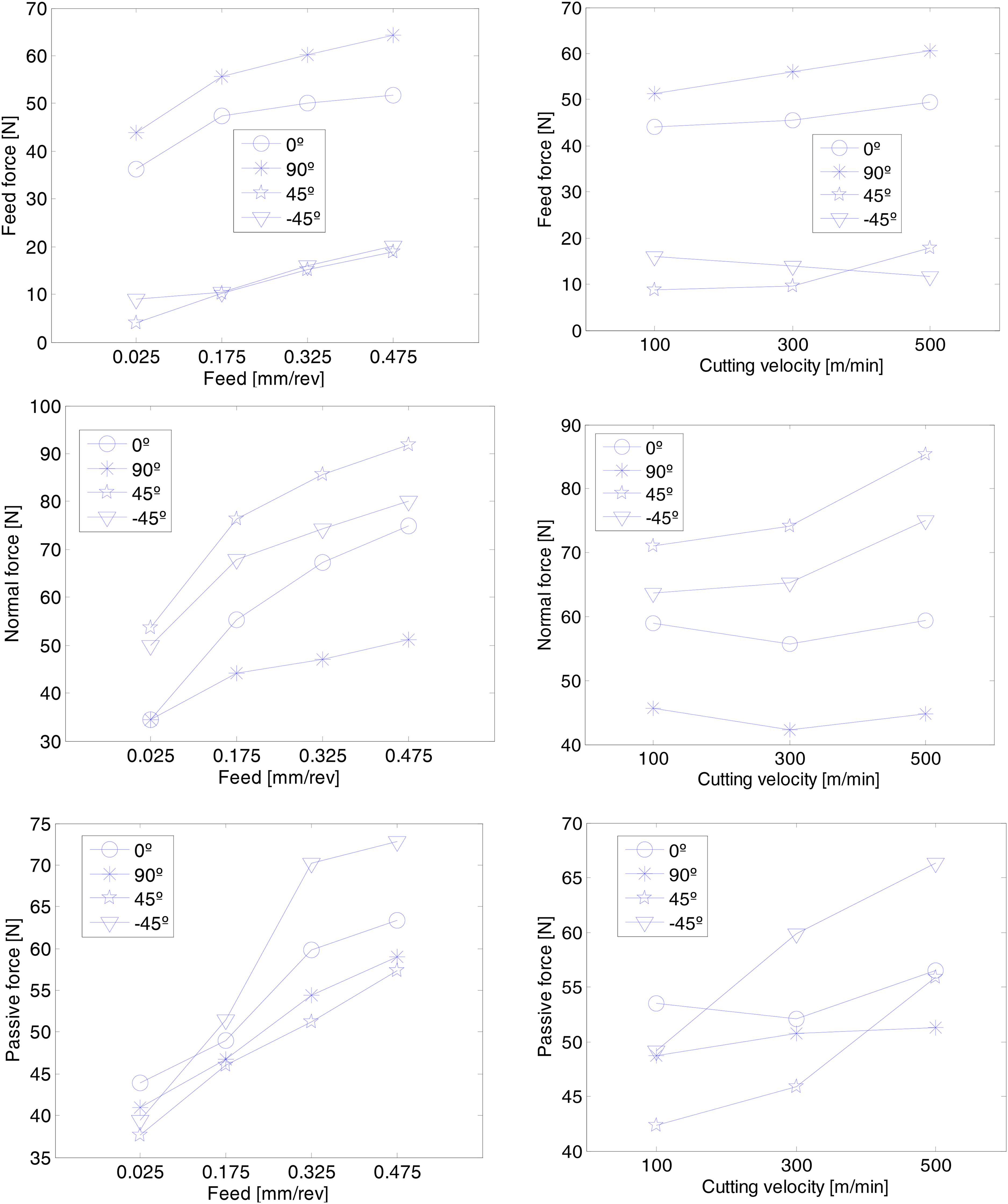
Cutting force components as a function of feed rate and cutting velocity for various fiber orientations.
As can be seen from the histogram (Figure 8), the feed and the normal forces are highly influenced by the fiber orientation. The normal force is maximal when θ is equal to 45° and it reaches a minimum value for θ equal to 90°. In contrast, the feed force is minimal for θ equal to 45° and maximal when θ is equal to 90°. Moreover, the passive force (axial force) seems to be slightly influenced by the orientation of fibers. It reaches a maximum value for θ equal to −45° and a minimum value for θ equal to 45°. These results are surprising because usually when θ is equal to 0°, the cutting forces are minimal since slotting requires less effort in the direction of the fibers. On the other hand, it can also be observed that the normal force is greater than the feed force except for 90° fibers orientation. This is also surprising because normally it is the feed force that must be the highest since the slotting is done in the opposite direction to the feed.
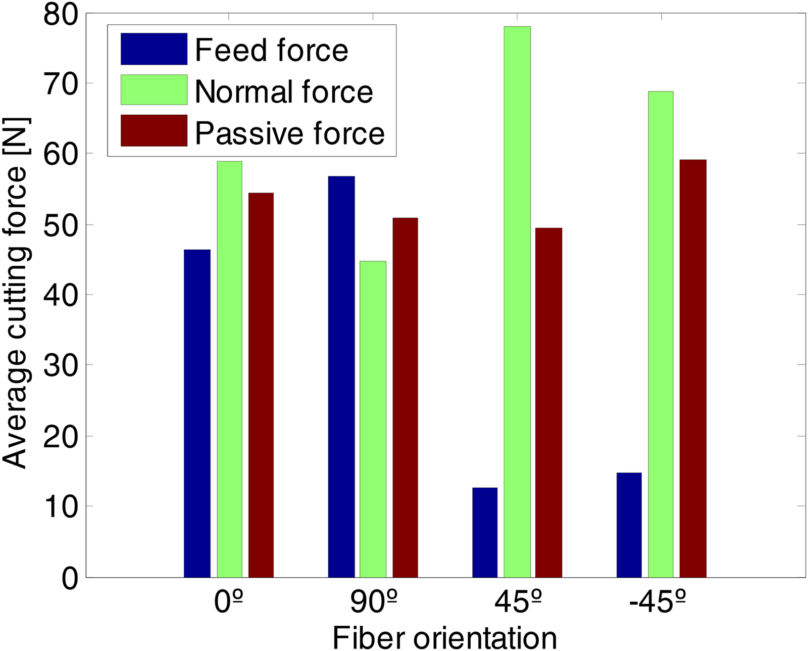
Evolution of the cutting forces as a function of the fibers orientation whatever the feed and the cutting speed.
This finding is in agreement with previous studies, 14 which perform trimming tests on FFRP plates.
On the other hand, these results can be explained by the fact that when the tool rotates during slotting, it forms an angle varying from 0° to 180° between the cutting force and the direction of feed. This means that the feed force changes sign continuously while milling the same slot. However, the normal force remains positive regardless of the angle of rotation of the tool. As a result, the resultant feed force is lower than the normal force. Similarly, this could explain why the cutting forces are not minimal when θ is equal to 0°.
On the other hand, surface roughness plays an important role in the final performance of composite materials and is a very important factor in evaluating the machining accuracy. Furthermore, a proper and effective preparation of the machined surface of composite prior to roughness measurement is essential. Hence, the surface cleanliness for each slotted specimen was checked carefully and blown prior to each measurement.
The first analysis shows that the surface roughness obtained by up milling mode is better than that obtained by down milling. The latter provides very inhomogeneous surface quality. This can be explained by the fact that the fibers during the up milling process are well supported by the forward material which makes them stiffer and more easily trimmed. 19 Therefore, only surface roughness obtained by up milling mode is retained in this work.
Figures 9 and 10 show the average arithmetic roughness values (Ra) as a function of the feed rate and cutting speed, respectively. It can be seen from these figures that the feed has a significant impact on the surface quality obtained. However,Figure 10 shows that the cutting velocity does not seem to have a significant impact on the surface finish quality obtained for the range tested. This finding is in agreement with the results of Delahaigue et al., 20 where they found that the surface finish depends largely on the feed rate, and to a lesser extent, on the cutting speed.
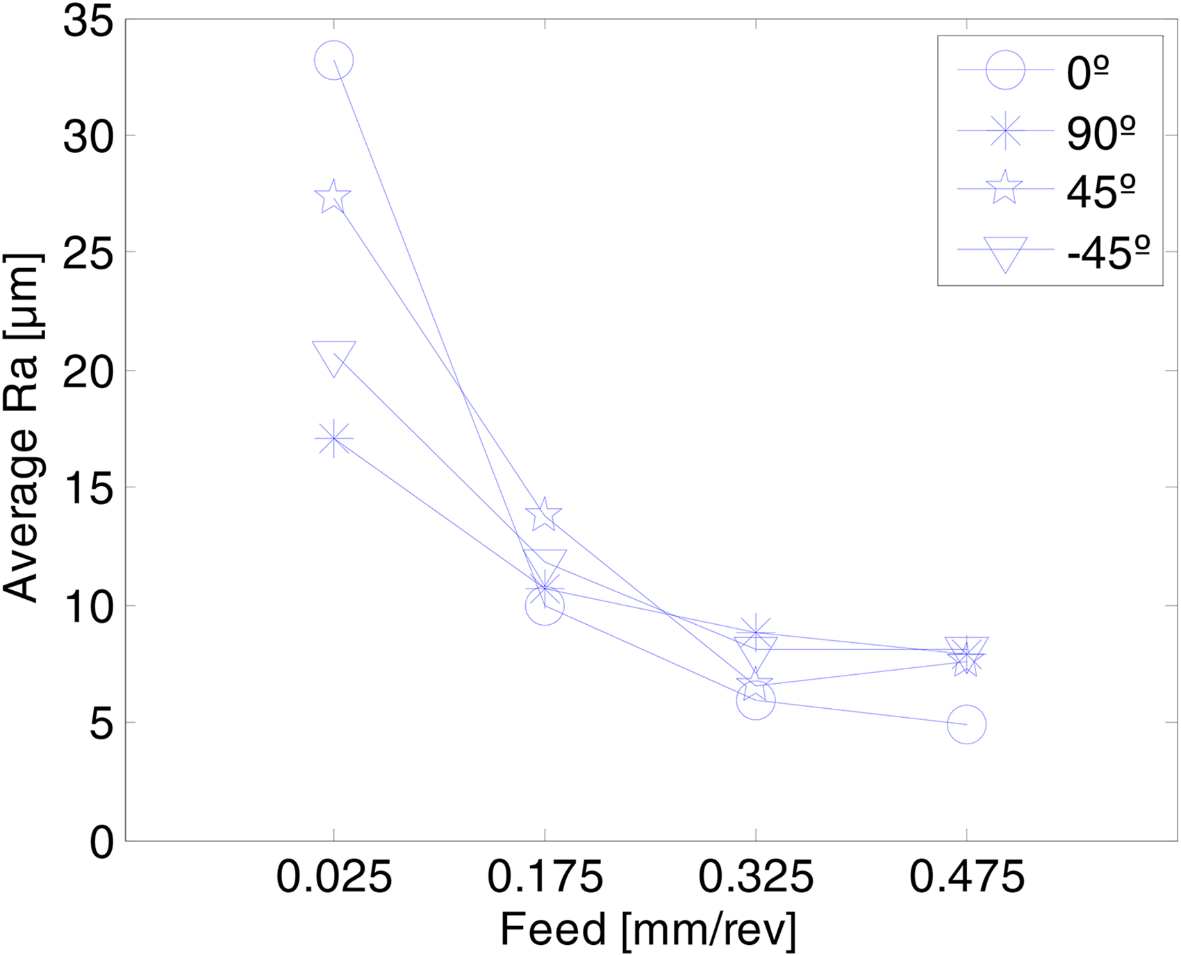
Evolution of the surface roughness as a function of the feed.
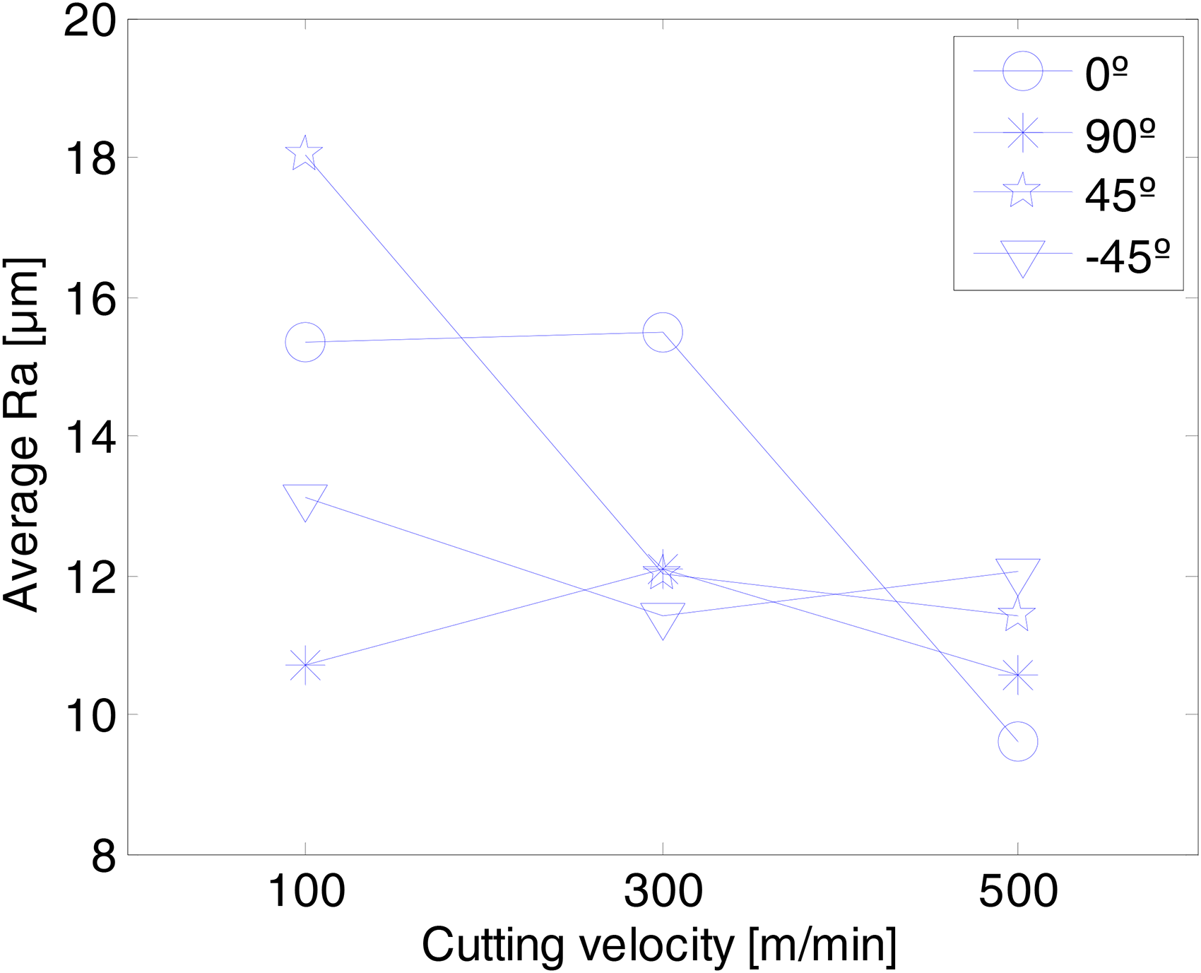
Evolution of the surface roughness as a function of the cutting velocity.
To examine the effects of machining parameters on the surface roughness, the percentage contribution of each factor involved in the test as well as its interaction whatever the orientations of the fibers were calculated based on the ANOVA test at a significance level of 5% (confidence level of 95%) 21 is presented in Figure 11.
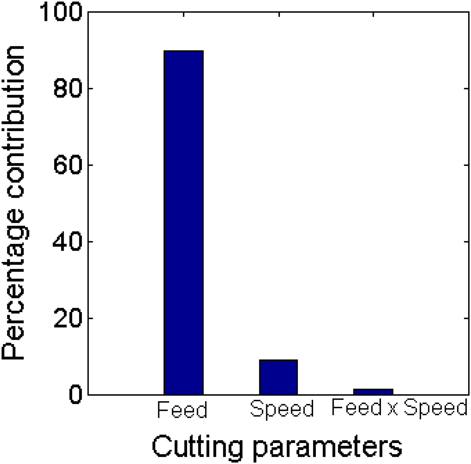
Percentage contribution of each factor on surface roughness.
Result shows (Figure 11) that feed rate is the most efficient process parameter that has a statistical and physical significance on the surface roughness with a percentage contribution of 89.99% representing the highest percentage of the process. Cutting speed with 8.83% of the total variation has less contribution on surface roughness. The interaction effect of the feed rate and cutting speed (1.18%) was found almost negligible.
On the other hand, Figure 10 shows that increasing the feed improves the surface roughness values regardless of the fibers orientation.
Figure 12 shows that the best surface roughness was attained when slotting along 90° fiber orientations. This can be explained by the fact that the fibers at 90° orientation were well sheared due to its well fixation in the matrix. 22 Furthermore, the worst surface roughness was obtained when slotting along 45° fiber orientations. This contradicts the findings of other studies, notably research published by Delahaigue et al., 20 where they found that the best surface finish is obtained for fibers oriented at 0° and the highest roughness is found for fibers oriented at 90°.
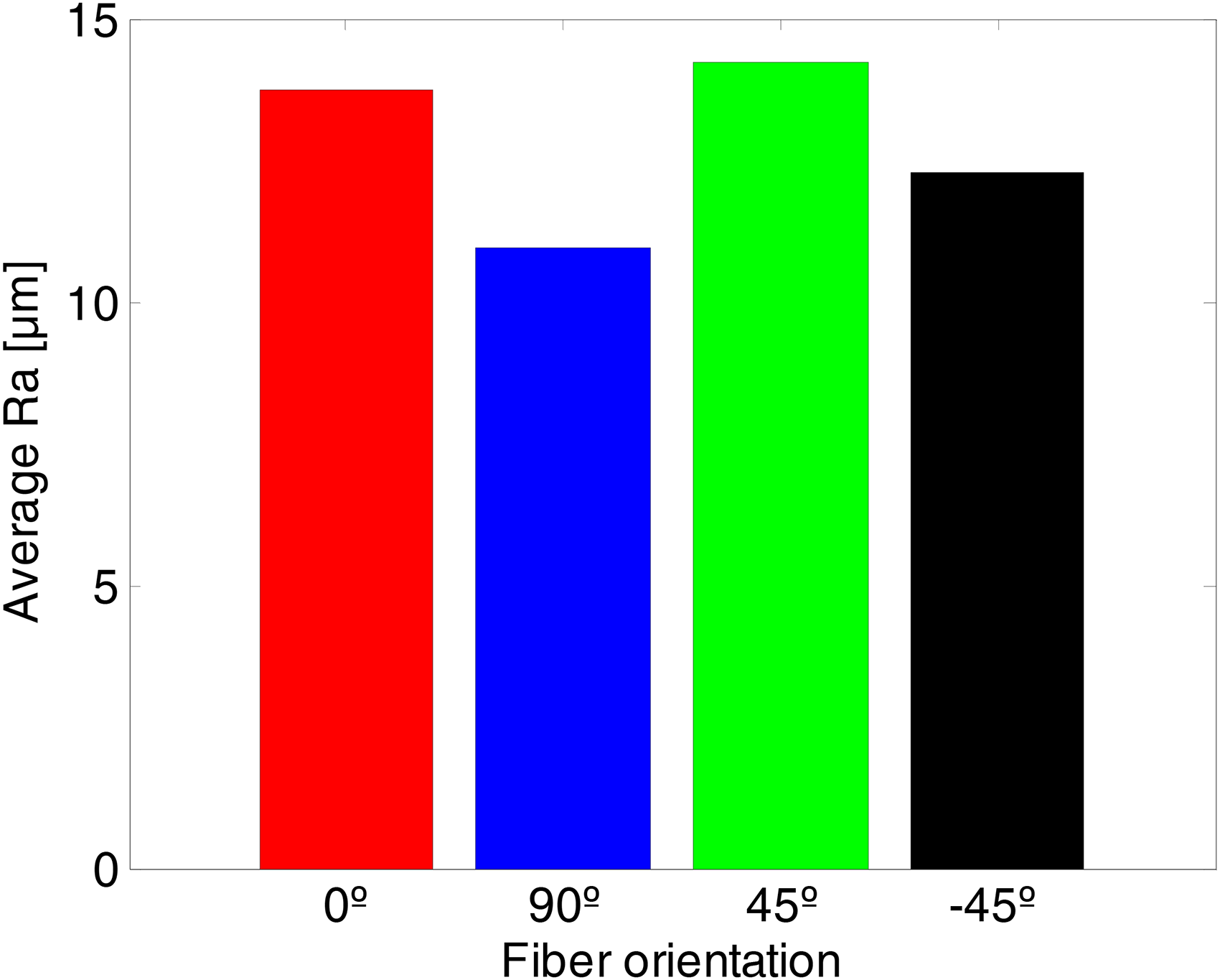
Evolution of the surface roughness as a function of the fibers orientation whatever the feed and the cutting speed.
As mentioned above and due to the lack of standardized method, there are several criteria other than surface roughness that can be used to evaluate the machining quality of composite materials, such as delamination and uncut fibers. As shown in Figure 13, uncut fibers or fluffing are the most common defect observed on the lateral sides of the majority of the slots during the machining of flax-fiber composites due to the softness and high flexibility of fibers.
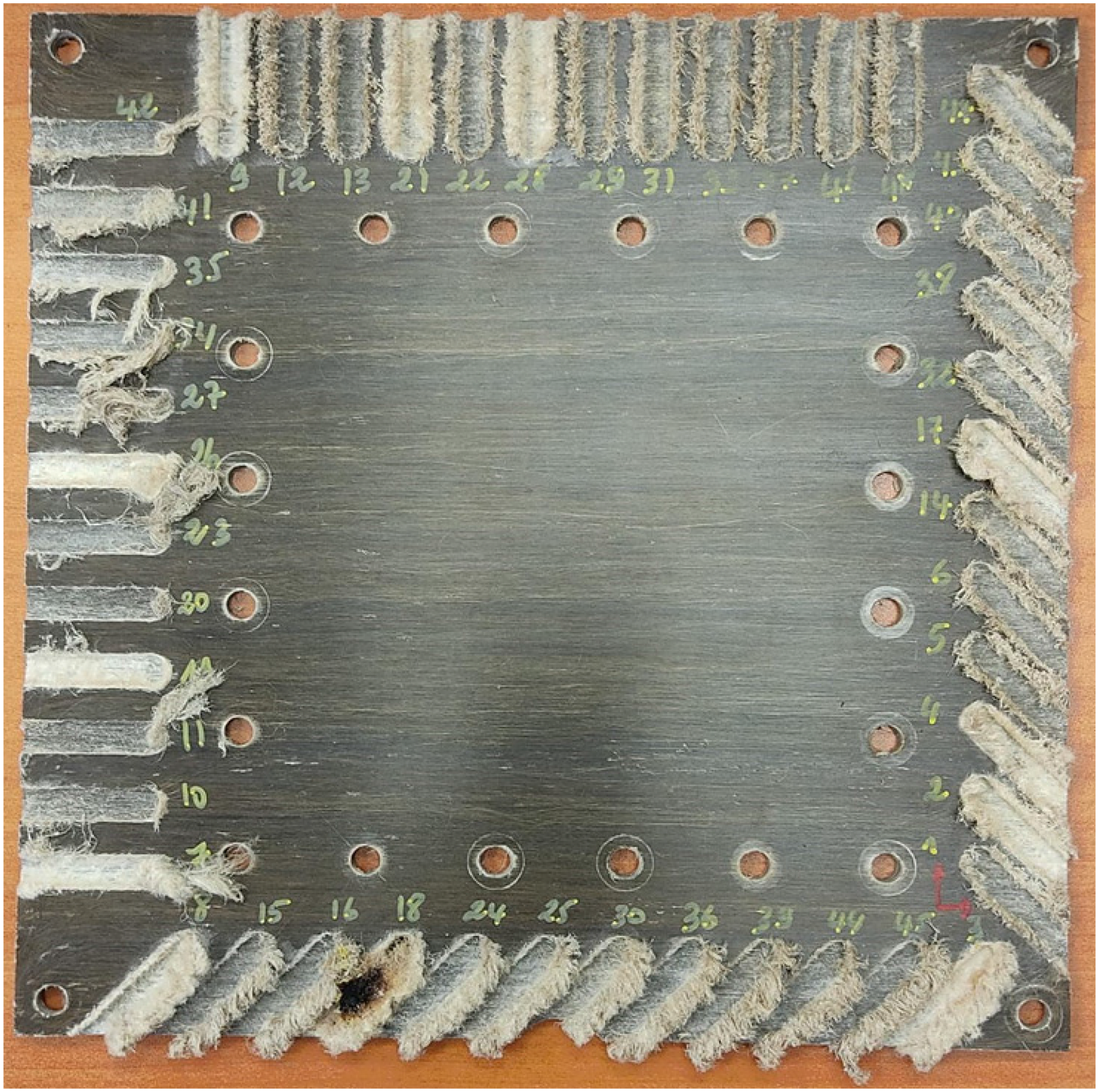
Flax/epoxy composite plate after slotting.
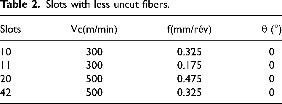
Moreover,Table 2 shows the slot numbers and their related cutting condition that minimize the apparition of uncut fibers. These slots are all machined at 0° fibers orientation with medium to high cutting speeds and feeds. Furthermore, this result can be explained by the fact that the fibers are easily sheared when they are oriented at 0° since they undergo less bending. The appearance of uncut fibers in the bottom of the slots oriented at 0° is caused by the reduction of the feed rate when approaching the bottom of the slot.
Slots with less uncut fibers.
As shown in Figure 14, burning of the matrix and fibers can appear during the dry machining of FFRP under certain conditions (case of slot 18). The observed burning is located at slot 18 and corresponds to the highest cutting velocity (500 m/min) and lowest feed (0.025 mm/min). This can be explained by the fact that when the feed is low and the cutting velocity is high, the temperature in the cutting zone increases and leads to machining-induced heat which is the most common cause of burning.
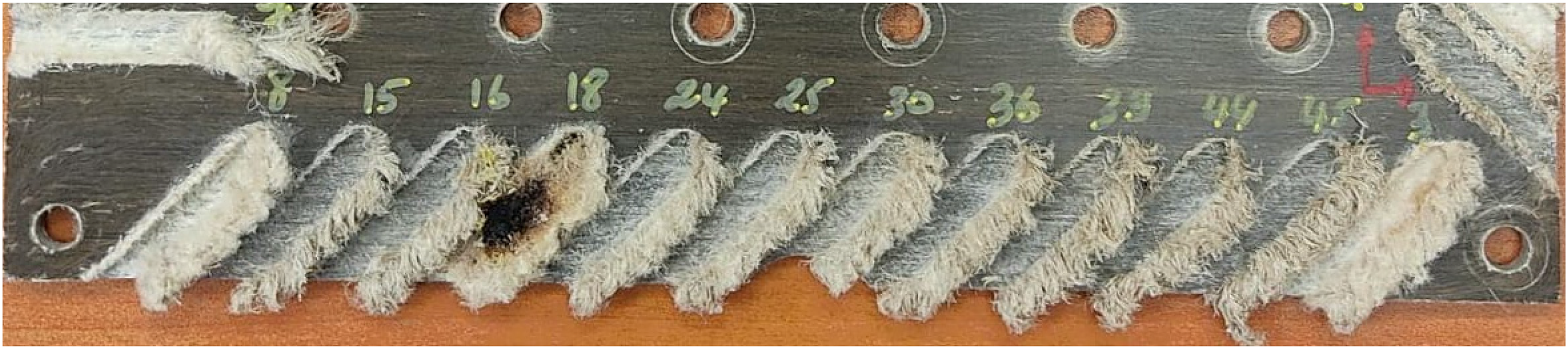
Burning of fibers at slot 18.
Conclusion
In the present study, slotting tests were conducted based on a CRD technique for FFRP composite material using two straight flutes “AMAMCO” solid carbide end mill and the cutting force, the surface roughness, and the delamination were analyzed. From the experimental results, the following conclusions can be drawn:
- The cutting forces were found significantly influenced by the fiber orientation. - The normal force was found the largest force except for 90° fibers orientation. - The feed force was found the lowest force except for 90° fibers orientation. - The feed force was lower at 45° and −45° fibers orientation. - The normal force was larger at 45° and −45° fibers orientation. - The passive force (axial force) was less sensitive to fibers orientation than the feed and the normal forces. - Fluffing was the most observed defect during machining flax fibers composites. - The combination of low feed high cutting velocity causes the burning of the matrix and fibers and has to be avoided during machining natural fibers. - The 90° fibers orientation provides the best surface roughness. - The 45° fibers orientation provides the worst surface roughness. - Slotting at 0° fibers orientations with medium to high cutting speeds and feeds minimize the apparition of uncut fibers. - Feed rate is the cutting parameter that presents the highest statistical and physical influence on surface roughness with a percentage contribution of 89.99. - Cutting speed has less contribution on surface roughness with 8.83% of the total variation. - The interaction effect of the feed rate and cutting speed (1.18%) was found almost negligible. - No tool wear was observed during slotting FFRP.
Footnotes
Declaration of conflicting interests
The authors declared no potential conflicts of interest with respect to the research, authorship, and/or publication of this article.
Funding
The authors received no financial support for the research, authorship, and/or publication of this article