
Abstract
This paper presents a comprehensive study on the modeling and optimization of an advanced suspension system, known as the Air Springs Inerter-Spring-Damper (AISD) system, incorporating an inerter element. A linear quarter car model is utilized to analyze the vibrational behavior of the AISD system when subjected to harmonic road disturbances. The steady-state response of the system is investigated by deriving the root mean square (RMS) values of the absolute relative displacement and acceleration of the sprung mass. To optimize the quarter car model, a criterion based on minimizing the absolute acceleration RMS while considering the relative displacement RMS is employed to calculate the inerter coefficient. The performance of the AISD suspension system is compared to that of both conventional quarter car systems and traditional air quarter car systems, with a focus on ride comfort and handling. The results demonstrate that the proposed AISD system outperforms the other two suspension systems, exhibiting a significant improvement in ride quality. Specifically, the AISD system achieves a 45% enhancement over the air suspension and an 82% improvement over the classic suspension system.
Introduction
The car suspension includes elements between the sprung mass (ms) and unsprung mass (mu) and prevents the transference of road disturbances from mu to ms as much as possible. Passive suspension systems still have a large share of the suspension market due to their lower cost and more accessible design. Over time, other elements have been added to the passive suspension to improve its performance. For example, in recent years, the inerter element and air spring have been used for this purpose. Suspension performance has a significant impact on riding comfort road holding of the car.1,2
The air suspension system has many advantages over the passive classic system. These benefits include weight loss systems, reduced chassis vibration and height adjustment. 3 Elbeheiry et al. 4 presented a simple model to illustrate the performance of the suspension system.
A lot of research has been done in the field of modeling and controlling the active and semi-active the air suspension systems in recent years, their modeling basis is the same as the quarter model. Their review is presented in Sorli et al. 5 and Ferraresi et al. 6 In this article, an inerter element7–11 is added to air suspension system and a new model is created, which is called IASD for short.
An inerter is a device whose force between its two ends depends on the acceleration difference between its two ends. This device was introduced by Professor Malcolm Smith in 2002. 12 The simple shape of the inerter has shown in Figure 1.
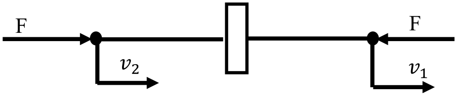
Schematic of inerter.
Three types of inerters are mainly used in research: ball-screw, rack-and-pinion, 13 and fluid inerter. 14 The applications of the element are very wide, for example, its uses in the passive vibration control,7–9,15 the automotive industry,10,16–22 the construction industry,23–26 and the space industry. 27
Smith and Wang 16 proved that the use of an inerter provides a 10% improvement in ride and stability criteria. Also, inerter can reduce the natural frequencies of the suspension. 28 Inerter was used in various passive networks in Chen and Smith,29–31 Chen et al.32–34 and the advantages of using it were investigated. The best combination for adding the inerter to the mechanical elements for the suspension system was achieved in Chen et al. 35
Yang et al. 36 study a hydropneumatic inerter-based suspension system based on the mechanical network theory of inerter and semi-active control. The results showed that the hydropneumatic inerter-based suspension system can achieve similar performance for semi-active control suspension.
Zhu et al. 37 introduced a new type of suspension system (SADHPIS)based on the “inerter–spring–damping” vibration isolation system and semi-active control.
Liu et al. 14 studied the damages on the road in the era of the passing of heavy vehicles and showed that these damages can be reduced with the inerter suspension system.
In recent years, extensive research has focused on integrating air suspension systems with various systems such as zero stiffness systems,3,38,39 hydro-pneumatic suspension systems, 40 magnetic suspension systems,41,42 and conventional suspension systems (e.g. leaf spring and coil spring). 43 These investigations highlight enhancements in the performance of the air suspension system when combined with these diverse systems, particularly in improving ride comfort and stability compared to the singular use of the air suspension system.
The integration of an inerter device within the air spring-based suspension system (AISD) represents a pioneering approach in automotive suspension design. This amalgamation harnesses the unique capabilities of both elements, aiming to enhance vibration isolation, mitigate road disturbances, and achieve an optimal balance between ride comfort and stability. By strategically combining the inerter with the air spring, the AISD system offers an innovative solution to effectively address the challenges associated with traditional suspension systems. This innovative design approach is poised to redefine the landscape of vehicle suspension technology by significantly improving ride comfort and stability, crucial factors in ensuring a smoother and safer driving experience. This study presents an in-depth analysis of the conceptual integration and its potential to revolutionize suspension system performance without discussing specific simulation outcomes, offering a unique perspective on advancing automotive suspension design. In this paper, an inerter is used in conjunction with an air spring in the quarter air suspension system (Figure 2(a)). It will be further seen that this new suspension system will considerably outperform the suspension system designed in Smith and Wang 16 due to the synchronous use of the flywheel and ISD vibration absorber.
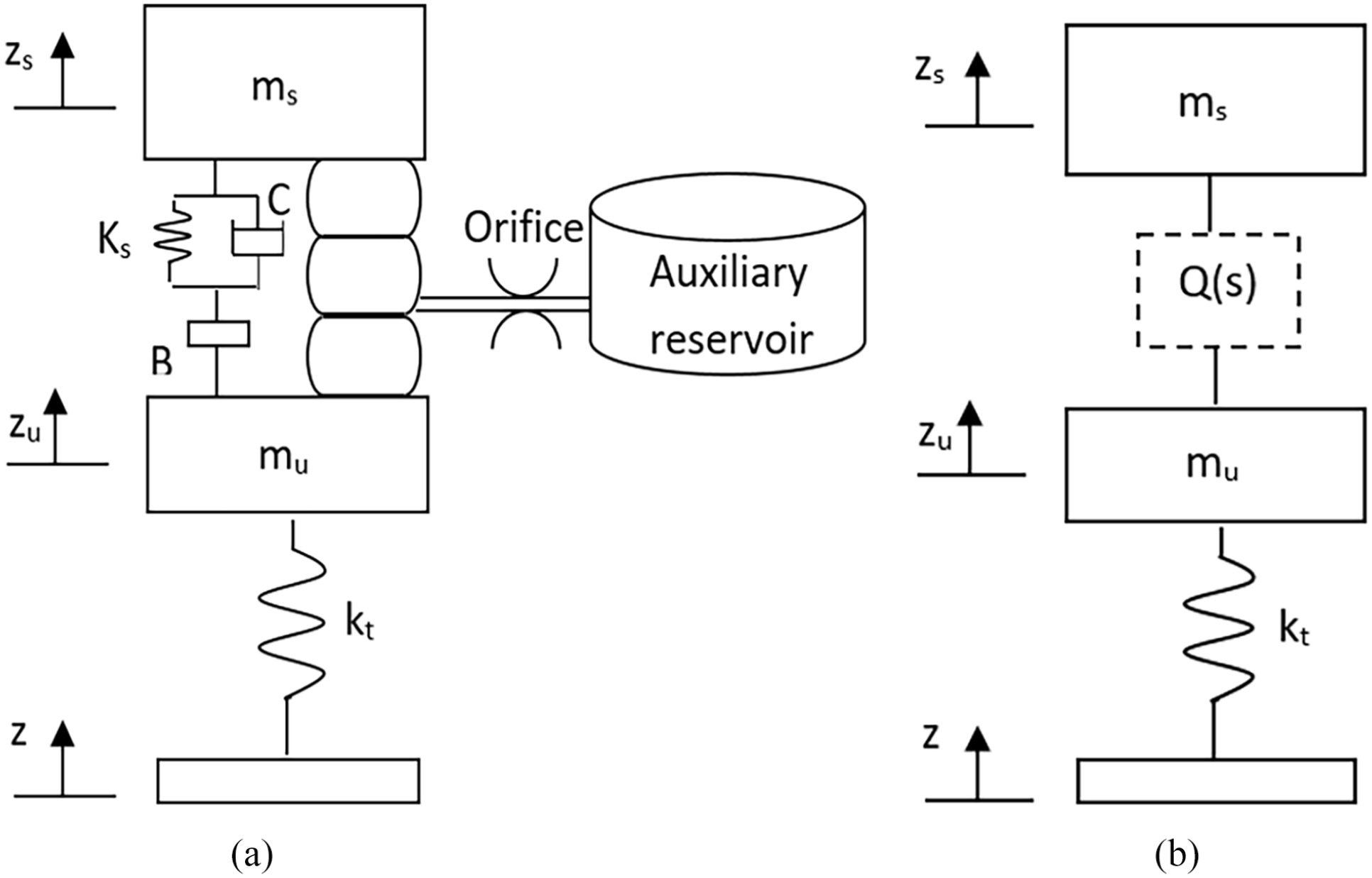
(a) The quarter air suspension model, (b) Analytical Model of air suspension
Theoretical and modeling analyses
The air suspension system consists of sprung mass, unsprung mass, damper, sir spring, and tire stiffness. The Figure 2 is shown these components. In Figure 2(a),
The quarter suspension system is presented in Figure 2(a). All analytical models of the car include the elements shown in Figure 2(b) and their main difference in force (Q(s)) is between the sprung mass and the unsprung mass.
The Laplace domain motion equations for a quarter suspension system are as follows.
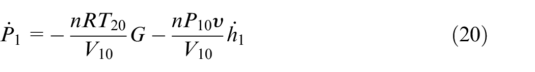
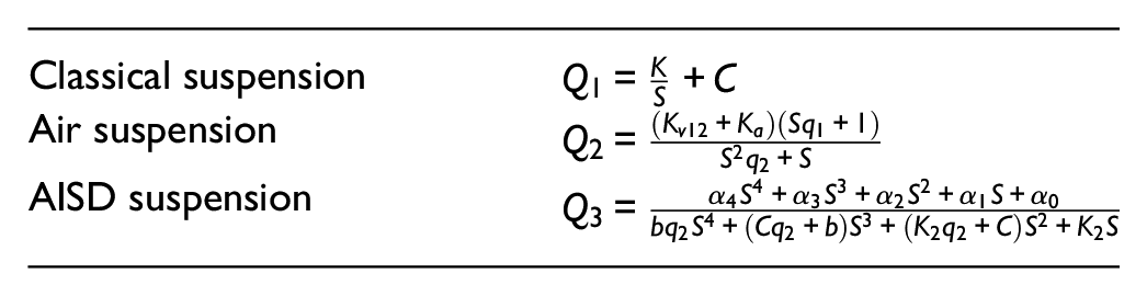
The transfer function (TF) of the various quarter suspension systems is obtained as follows:
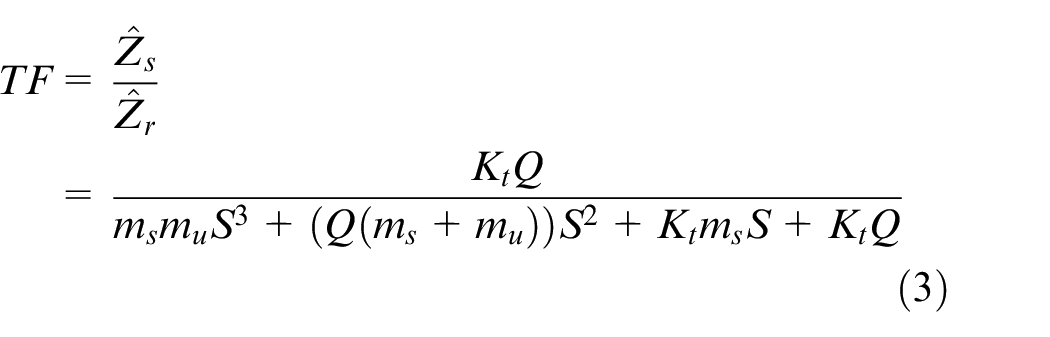
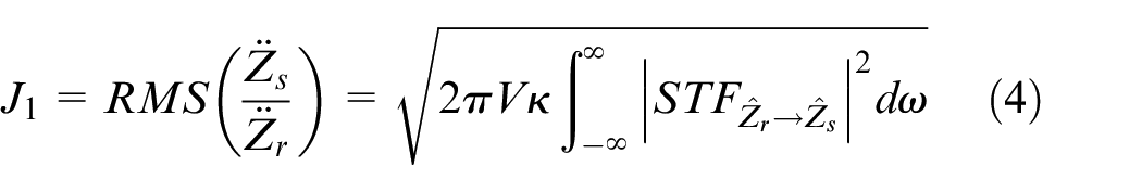
In accordance with Jin et al., 7 the TF of ride comfort is equal to (3), and the RMS (Root Mean Square) of the vertical acceleration of the body is used as equation (4) for calculating the ride comfort.
The
after some manipulations, the transfer functions used to show road holding and Jumping sprung mass to unsprung mass (
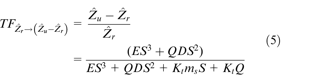
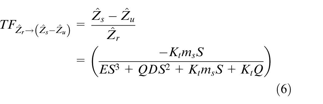
Where,
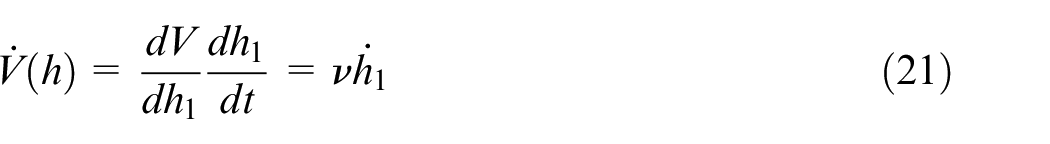
That is, all equations (3) to (8) are calculated for each suspension system using the Q(s) or admittance of that suspension system and are compared with each other. For this purpose, it is necessary to calculate the admittances of the AISD suspension systems. In the AISD system, the Q(s) is equal to the sum of the air spring and inerter force:

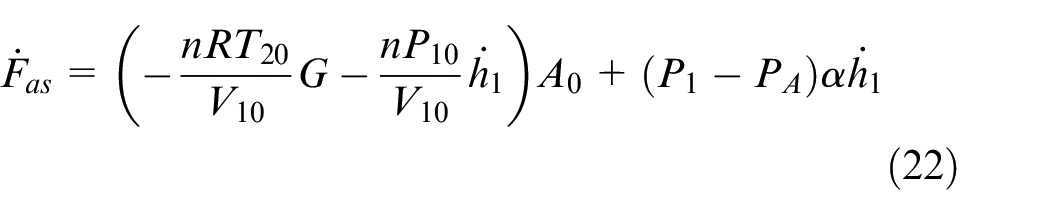
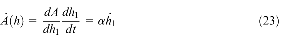
In this suspension system, the air spring vertical force shown with
The air suspension by itself consists of three subsystems, the gas spring, the auxiliary reservoir and the resistance which connects them together, the reservoir and resistance constitute the damping device which makes it possible to damp oscillations. The force exerted by the air spring can be written (Figure 3):

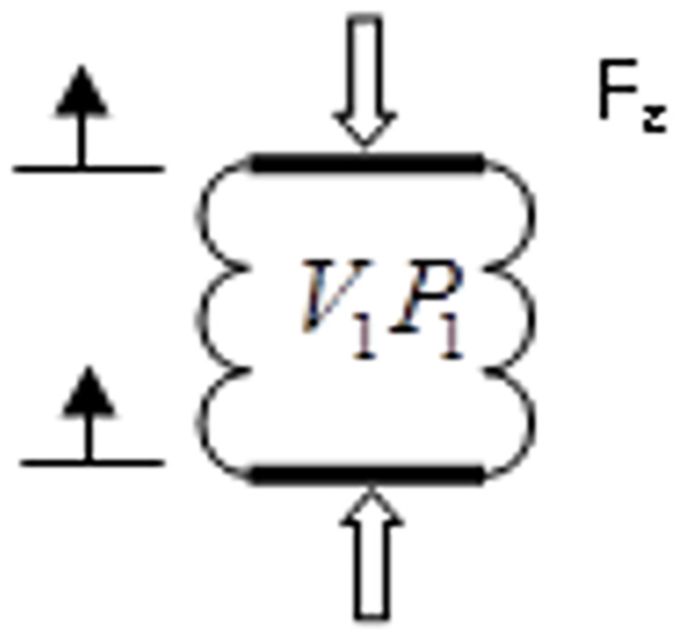
Force pushed to air spring.
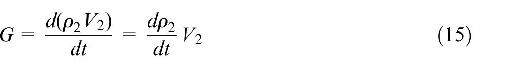
That is, that the force is proportional to the air spring internal pressure, P1, Initial pressure of the air spring and the air spring effective area, A. As this area does not correspond to geometrically defined value, it is assessed by means of constant internal pressure tests in which force F is measured while varying height h. The mass flow from the air spring to reservoir can be expressed by the continuity equation:

The flow becomes positive as the tank fills.
Assuming the expression for density through a polytrophic transformation (
Deriving and subsisting gives the pressure gradient
Where
The same steps followed to obtain equation (6) are now used at the reservoir end in order to link the mass flow rate to the reservoir pressure (
And assumed polytrophic transformation:
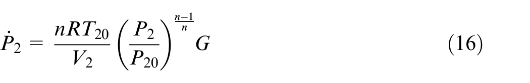
Where
The rate through the resistance can be defined versus pressure at its end. either by using the analytic function or by mapping experimental data. In the first case, and in accordance with ISO 6358, we have:
Where pressure PU (P upstream) and PD (P downstream) are defined as

And the nonlinear air spring force obtains by integration of Fairspring.
Numerical simulation can be performed according to the above block diagram (Figure 4) by using appropriate software such as MATLAB/SIMULINK. To obtain the frequency response of the nonlinear system, the data which have been defined in Table 1 have been used.
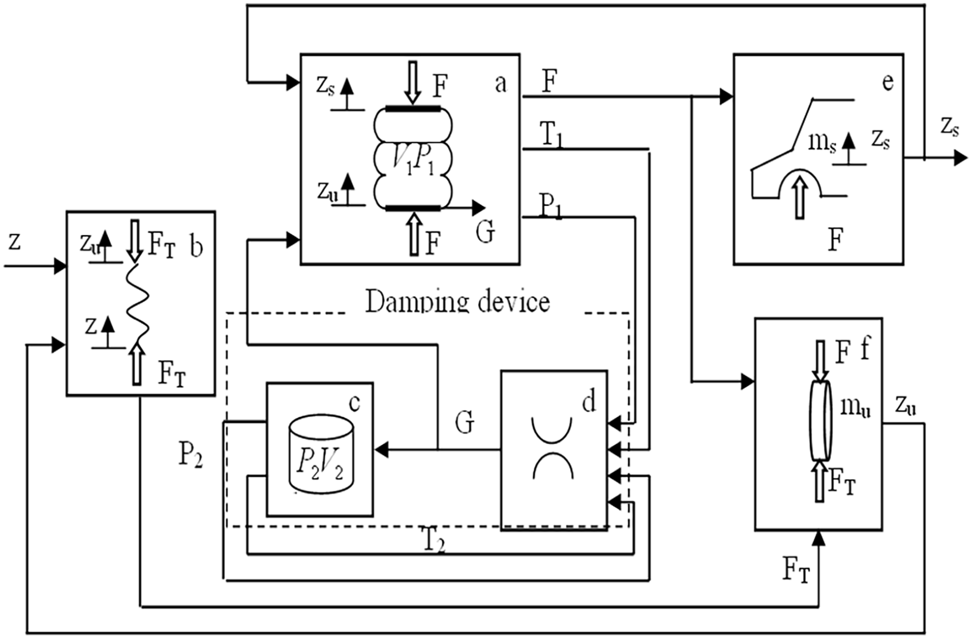
System block diagram.
Definition of linearization point.
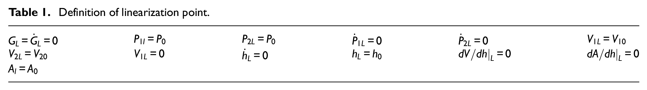
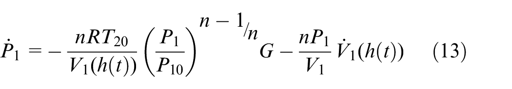
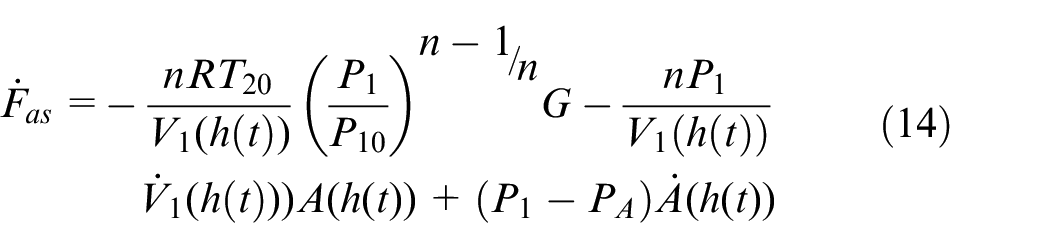
Linearized model
For linearizing of two degrees of freedom nonlinear quarter car model, at first, the air spring force (Fas) must be linearized. The linearization of Fas is done using Taylor series expansion in the neighborhood of the point denoted by subscript L. The linearization point has been defined in Table 1.
According to Table 1, linearizing equation (13) gives
Where
Linearizing equation (14) gives
Where
When the suspension dynamics are very fast, the pressure waves do not have time to reach the reservoir. Therefore, at high frequencies, the suspension behaves like a closed system formed (G = 0) by the air spring alone. The stiffness in this case, is given by:
By defining ka and kv1 as


Linearizing the reservoir model provided by equation (16) gives:
Equation (10), that is, the expression for flow rate, is at a vertical tangent at the linearization point. In this case, we thus opted for secant linearization to represent flow rate over a significant range of pressure drops.

Where the parameter RF which defines the linear resistance can be related to conductance through expression
When the suspension dynamics are very slow, the pressure of the air spring and auxiliary reservoir are equal. Therefore, at low frequencies, the suspension behaves like without a resistance system (RF = 0). The stiffness in this case, is given by:
By defining kV12 as

Linearizing the reservoir model provided by equation (9) gives:
The transfer function between suspension height h and air spring force (F) is obtained by performing a Laplace transform:
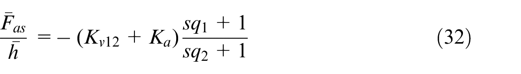
Where:
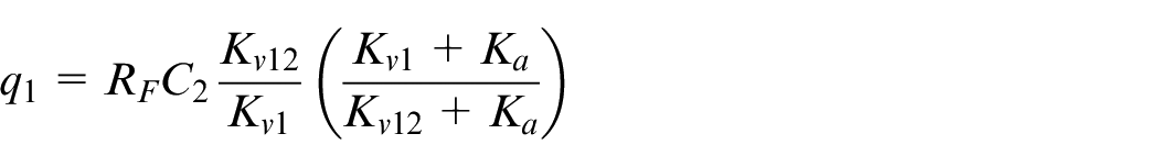
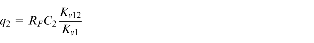
As a result, the admittance
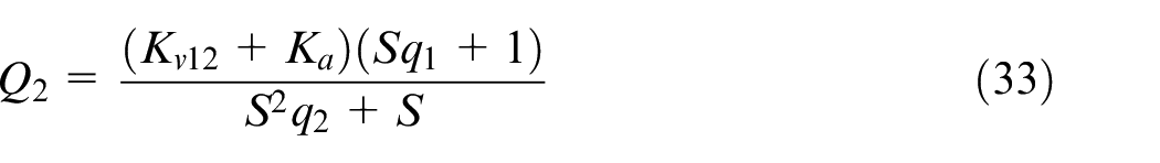
The AISD suspension system according to Figure 2 consists of a vibrating absorber and an air spring with its storage tank. As a result, the admittance of the AISD suspension system is calculated as equation (34).
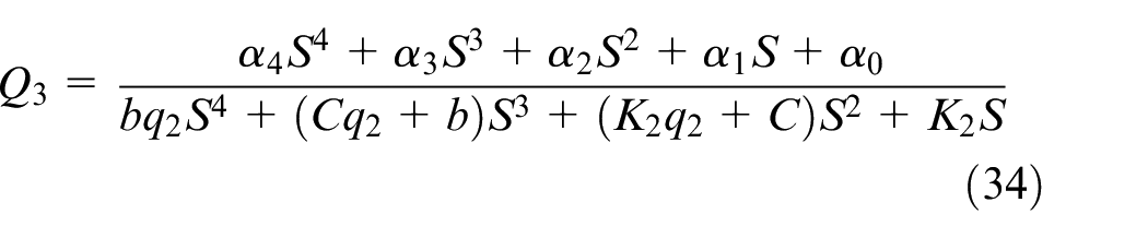
Where,
Table 1 gives the admittance Q for the classical, air suspension and AISD suspension systems.
The force on the inerter element is calculated as follows. The schematic of the inverter is shown in Figure 1.

Where, b is the inerter coefficient per kilogram; V is the velocity of the ends of the inerter element. A corresponding mechanical element of mass was considered in the standard simulations between mechanical and electrical elements for the electrical element of the capacitor. But this simulation was not complete and the mechanical element corresponding to the electric capacitor was manufactured, which was called inerter. 12
Simulation
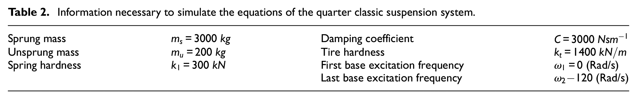
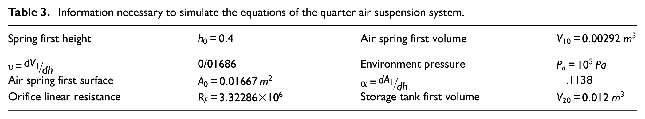
In this section, all equations (2) to (8) are initialized and simulated for each classic, air and AISD model based on their admittance. The various values assumed for the stiffness and damping coefficients, sprung and unsprung masses belonging to the classic model are given in Table 2 and belonging to air suspension system are given in Table 3. The air spring used in this article is the T26pirelli/Cfgmma model.
Information necessary to simulate the equations of the quarter classic suspension system.
Information necessary to simulate the equations of the quarter air suspension system.
In our research, the computation of optimal values for inertance and parallel spring stiffness (K2) was achieved through the establishment of two distinct objective functions. These functions aimed to optimize the RMS of the vertical acceleration of the car body (J1) and the RMS of the relative displacement between the sprung and unsprung masses (J2). A key objective was to minimize the RMS value of the acceleration of the sprung mass for improved ride quality, while simultaneously minimizing the RMS value of relative displacement to enhance the vehicle’s stability on the road.
Mathematically, we sought to find the optimal state represented by the conditions:
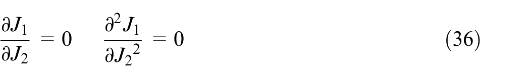
The values of K2 and b were determined based on the graphical representation showcased in Figure 5, depicting the changes in these parameters. The minimum points identified on each diagram in Figure 5 correspond to instances where the acceleration of the unsprung mass is at its lowest, concurrently minimizing relative displacement. These points signify a state of optimal stability along with improved ride quality, serving as a crucial criterion in our numerical simulations.
RMS of the sprung mass acceleration (J1) versus of RMS of the relative displacement (J2).
For the AISD model, the data for these tables are used for the air spring,
Damping in suspension systems
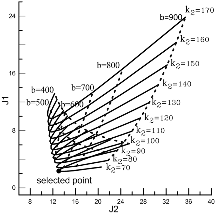
Equations of motion of the quarter suspension system are simulated according to equation (2) for each suspension system in the Matlab/Simulink software based on the admittance (Q) of each suspension system and the sprung mass (ms) displacement is achieved for them based on Figure 6. In this figure the step function is 10 cm.
In these three suspension systems, the displacement of the sprung mass can be examined based on two perspectives. One of them is the maximal displacement of sprung mass and the other one is in terms of the duration of damping, In the classic suspension system for the step input of 10 cm, the maximum displacement is 1903.0 m and it is 0.177, and 0.1475 in the air suspension and AISD suspension systems respectively. Therefore, the maximum displacement in the AISD suspension system is the least.
In the case of the duration of damping the time it takes for a sprung mass to be taken up to a maximum of 1 cm more or less than the step input is considered. This duration is considered as 7.608, 3.33, and 2.69 for the classic suspension, air suspension and AISD suspension systems respectively.
Therefore, the AISD suspension system outperforms the classic suspension and air suspension systems in terms of maximum displacement of the sprung mass and damping.
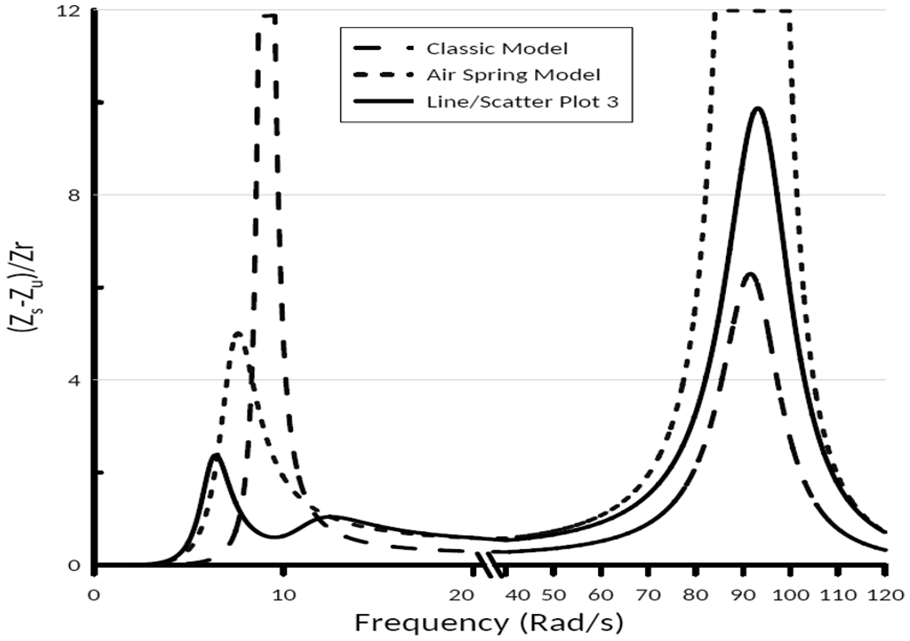
Transfer function and riding comfort criterion
Transfer functions of classic suspension, air suspension, and AISD suspension systems are obtained by equation (3) and its Q in Figure 7 within the ranges of 0–120 rad/s. Given that the amount of riding comfort is represented as
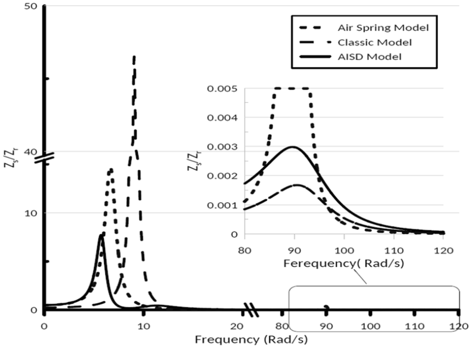
The transfer functions from the road disturbance
In Figure 7, it is clear that first the AISD, air, and classic models have good transferability respectively because both transferability and first natural frequency are lower in the AISD model. The first natural frequencies are 5.73, 6.66, and 9.06 rad/s in the AISD, air, and classic models that their displacement transfer function values are 7.7197, 14.71, and 45.5, and the lowest value of the transfer function is associated with the AISD model. Therefore, this model has the less natural frequency and less transfer function in this interval and acts better in terms of transferability or transfer function.
Because lowering the natural frequency will increase the comfort of the suspension system, 45 the AISD suspension system outperforms the other two suspension systems in both intervals and the entire range of 0–120 rad/s in terms of transferability and ride comfort.
The amount of the ride comfort or
Stability criterion
Indicators of this criterion are the vertical forces applied on the tire. These forces are obtained as follows:

As a result, each
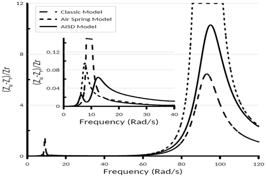
The stability transfer functions that is,
As shown in Figure 8, the AISD suspension system has the lowest first natural frequency and the amount of stability transfer function than the other two models. According to Figure 8, and for higher frequencies, the AISD suspension transfer function lies between two classic and air suspension system that does not differ significantly from the classic suspension system. For a precise examination of this criterion in the entire range of 0–120 rad/s, equation (7) is used to calculate the stability value.
The comparison between these values shows that the AISD suspension system while resolving the contradiction between the two criteria of riding comfort and stability, has improved stability by 46%.
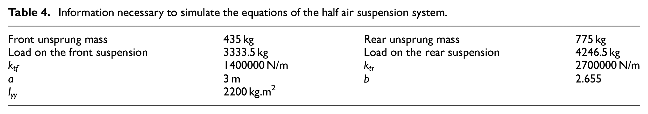
For deeper exploration of the turning angle stability in three cars − incorporating the conventional suspension model, air suspension system, and air suspension system integrated with inertiar − an analysis based on the ½ car model (Figure 9) was conducted using data provided in Table 4. The parameters in this table are crucial for simulating equations related to the half air suspension system. They represent specific values such as masses (unsprung and load), stiffness coefficients for both rear and front suspensions, inertance, distance between suspensions, and moment of inertia. Utilizing this information, simulations can be performed to analyze the behavior, stability, and performance of the half air suspension system, particularly in relation to different aspects such as response to loads, vibration damping, and stability during turning angles. The input for both front and rear suspension systems was configured as illustrated in Figure 10 for simulation purposes. Findings from the simulations, as depicted in Figure 11, indicate that the conventional suspension system and the air spring suspension system exhibit greater degrees of twist angle compared to the AISD suspension system. Additionally, they take more time to achieve stability, noted as zero twist angle.
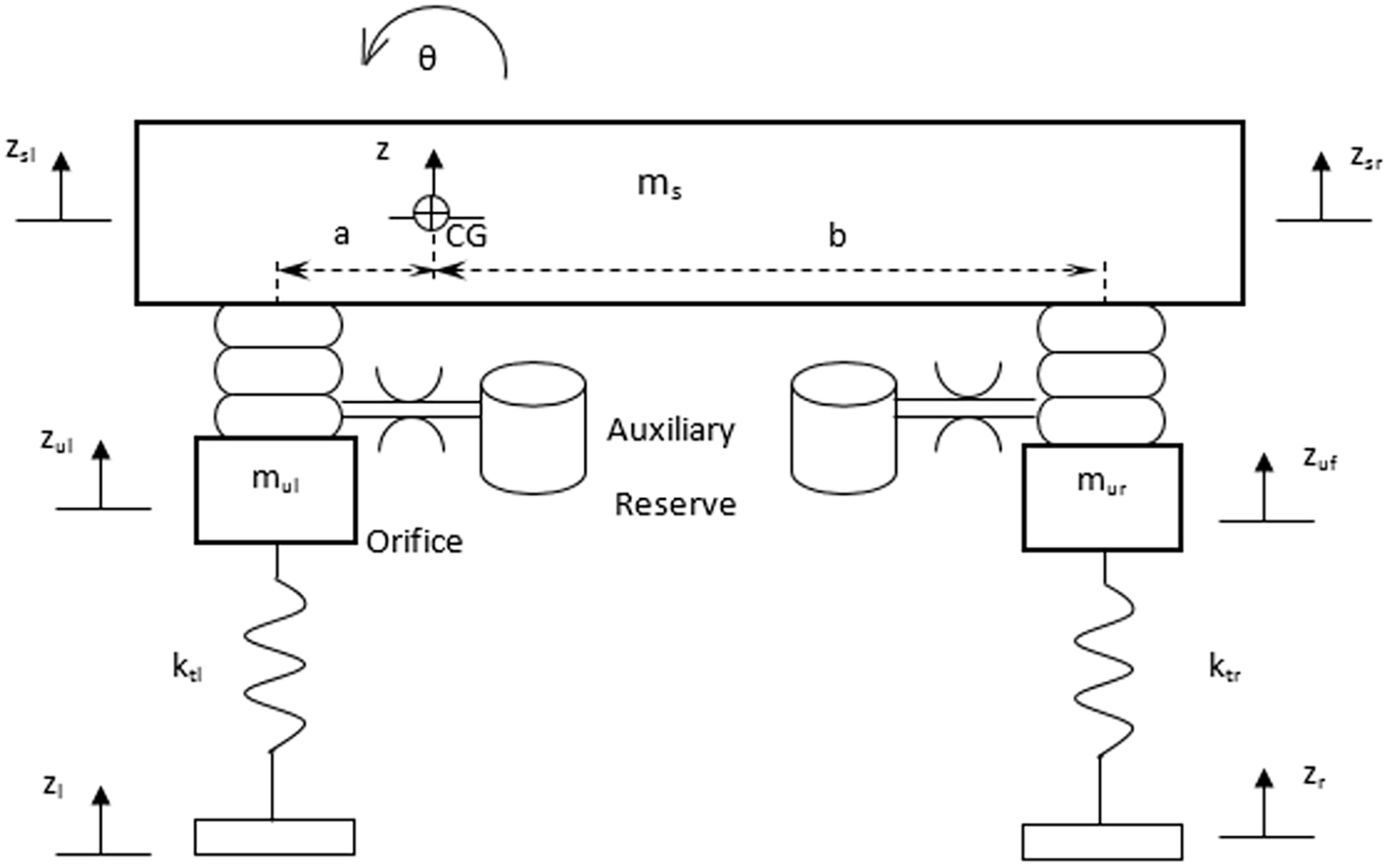
Half car suspension model.
Information necessary to simulate the equations of the half air suspension system.
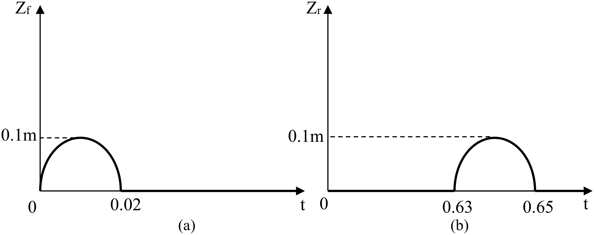
Input of front suspension system (a), and input of rear suspension system (b).
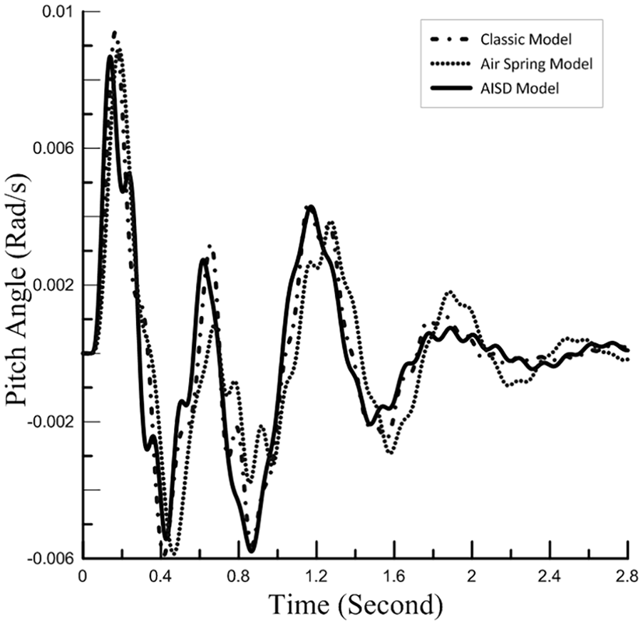
Pitch angle versus time in a half car suspension model.
Deflection criterion
The deflection criterion is based on the distance or space between the sprung and unsprung masses. As this criterion is lower in the suspension system, it means that the suspension system works better. The deflection transfer function is obtained by equation (6). This transfer function for the classic, air and AISD suspension systems is obtained within the range of 0–120 rad/s and presented in Figure 12.
The deflection transfer functions that is,
As shown in Figure 12, the AISD suspension system reduces the first natural frequency and has a lower deflection transfer function at this frequency, but the classic suspension system works better at higher frequencies. Equation (8) is used to obtain the exact value of the deflection function. The amounts of deflection for classic, air, and AISD suspension systems are equal to
Conclusion
In this paper, a new type of suspension system was designed, which was created by adding an ISD vibration absorber to the suspension system. The suspension was then modeled with classic and air suspension systems, and their behavior was simulated in terms of riding comfort, stability, and deflection. The following results were obtained after the simulation.
The transfer ability or transfer function is improved in the AISD suspension system.
The sprung mass (
In terms of ride comfort criteria, the AISD suspension system is 82% better than the classic or initial suspension system and 45% better than the air suspension system.
Although the air suspension system improves riding comfort and deflection, its impact on its stability is negligible and even negative. But with the addition of a vibration absorber with an inerter element called ISD, improves the initial or the classic suspension system’s stability by 46%.
In terms of stability criteria, the AISD suspension system is 55% better than the classic or initial suspension system and 42% better than the air suspension system
The improvement of the initial or classic suspension condition in terms of riding comfort, stability, and deflection with the addition of the ISD vibration absorber in the suspension systems designed in Smith and Wang 16 is 4%, 6%, and 16% respectively values are 82%, 46%, and 55% for the designed AISD suspension system in this article. So, the performance of the suspension system designed in this article is much better than the one designed in Smith and Wang. 16
Footnotes
Acknowledgements
The authors would like to thank the Engineering Faculty and LPPM of Universitas Pembangunan Nasional “Veteran,” Jakarta, Indonesia, for the internal research grant scheme of RIKIN 2022 awarded.
Declaration of conflicting interests
The author(s) declared no potential conflicts of interest with respect to the research, authorship, and/or publication of this article.
Funding
The author(s) received no financial support for the research, authorship, and/or publication of this article.