
Abstract
The paper reports on the use of a developed novel and specific test-rig for the assessment of performance of radial lip seals of automotive transmissions, with particular emphasis on determination of thermal performance. The test-rig can accommodate original components from a donor vehicle, thus accurately represents vehicular conditions. The specific aim is to experimentally determine the effect of shaft surface roughness parameters on the generated contact temperature. Excessive exposure to high temperatures can accelerate degradation and aging of elastomeric seals, resulting in increased wear. Corundum and CBN (Cubic Boron Nitride) ground shafts are used to ascertain the effect of surface roughness parameters in the shaft seal conjunction. An analytical thermal model is also developed in combination with temperature measurements to determine the exact temperature in the lip seal-shaft contact. It is shown that depending on the type of shaft surface grinding process some potential correlation exists between roughness parameters and generated contact temperatures. It is also shown that the contact temperature can be several degrees Celsius higher than those measured in the proximity of the seal contact.
Introduction
Radial lip seals are essential components in various industries, including oil and gas, chemical processing and automotive. Seals create a physical barrier, effectively contain the lubricant and protect against ingression of contaminants, ensuring reliable and efficient operation of machinery. Walter Simmer patented the first functional rotary shaft seal in 1938. 1 During operation, a thin film of lubricant separates the sealing lip and its seat, which is typically made of an elastomeric material used in the case of automotive lip seals. However, high temperatures in the sealing gap can impair its performance, leading to the aging of the elastomer and reduced sealing effectiveness.2,3 Elevated temperatures can lead to changes in elastomer properties, making them more compliant and less resistant to deformation. 3 Therefore, investigating temperature variations in the sealing gap is crucial for improved performance, controlling leakage, ensuring material compatibility, understanding wear and failure mechanisms, enhancing system reliability and validating predictive models.
Understanding of thermal behaviour of lip seals with key design parameters and fluid film effects has been reported in the second half of the 20th century.4–8 With specific focus on investigating the effect temperature on the radial lip seal performance, Upper 4 developed a thermal model, based on an electric circuit analogy to determine contact temperature in rotary shaft seals. Upper’s parametric model considered factors such as lubricant type, shaft diameter, operational speed and temperatures of surrounding air and oil. High temperature gradients were observed within the seal due to low thermal conductivity of the elastomer. Brink 5 investigated the influence of radial load on sealing ring performance and demonstrated a correlation between seal lip temperature and seal lifespan using infrared technology. Horve 6 emphasised the importance of maintaining a critical lubricant film thickness to prevent seal leakage and highlighted the importance of the operating temperature on the reliable sealing performance. Stakenborg and van Ostayen 7 used thermo-elastic finite element analysis to study the effect of temperature on the sealing gap. They found that the largest amount of heat flows through the shaft and the heat flow into the seal has only a minor effect on the contact temperature. Poll and Gabelli 8 investigated lubricant film thickness at higher temperatures using magnetic lubricants enriched with metal particles. Their results provided insights into lubricating film formation as a function of shaft rotational speed.
Recently detailed numerical analyses have led to significant advances in the understanding of thermal seal behaviour.9–20 Kang and Sadeghi 9 solved Reynolds and energy equations to investigate thermal effects in seals, noting that rising temperatures increased lateral leakage rates. Meyer et al. 10 and Plath et al. 11 employed iterative models to determine contact pressure, friction and generated heat between the seal and the shaft. Magyar et al. 12 and Frölich et al. 13 presented models for studying macroscopic aspects in radial shaft sealing systems. These studies highlighted the influence of shaft size, rotational speed and lubricant temperature on frictional heat flow. Kim and Shim 14 used a Mooney-Rivlin model to explore the relationship between static pressure of the sealing lip and its thermal behaviour, thus emphasising the role of interference fit. They found that increased interference could lead to local separation between the shaft and sealing lip, potentially causing failure. Silvestri and Prati 15 focused on estimating the frictional torque and contact pressures in rotary shafts, observing changes in temperature, contact width and torque under different conditions. Their work showed the influence of deformation, known as ‘bell-mouthing’ on contact area and pressure distribution. The influence of temperature on radial shaft seals extends beyond its mechanical behaviour. Szabó and Váradi 16 showed that temperature cannot be ignored in seal analysis during operation. Their model considered the viscoelastic behaviour of the sealing materials, preloading of the sealing lip and the effect of frictional heat on material properties. Guo et al. 17 found that elastomeric aging, which can be a consequence of high contact temperatures, significantly reducing the modulus of elasticity of the sealing lip and affect the pumping rate. Daubner and Haas 18 used computational fluid dynamics to study contact temperature, calculating local heat transfer coefficients along the seal surface. Feldmeth et al. 19 stated that frictional heat generated in the contact dissipates mainly through contiguous surfaces by conduction. Using a Finite Element Method (FEM), Lee et al. 20 modelled the thermo-mechanical behaviour of the elastomer seal material. They simulated temperature distribution due to frictional heating and investigated the contact width and pressure distribution with different tolerance fits using a flexible test-rig.
An important factor which can affect the performance of radial lip seals is the surface roughness of seal and particularly the shaft counterpart. Standards such as DIN, 21 ISO, 22 and RMA 23 provide specifications for surface roughness and shaft lead angles. Additionally, DIN EN ISO 4287 24 defines parameters for surface finish using the stylus method. The normative standard JIS B0602 25 specifies terms, definitions and parameters for determining surface roughness, waviness and primary profiles of engineering surfaces. Maintaining the appropriate average roughness is crucial in ensuring appropriate lubrication and prevent temperature rise due to lubricant starvation. Radial lip seals prevent leakage by establishing a reverse pumping effect between the seal lip and the shaft surface. Buhl 26 introduced a surface characteristic value to capture the active and passive components of the lubricant conveying effect. Active conveying occurs when the shaft rotates, creating a pumping action that pushes the fluid away from the seal. Passive conveying, on the other hand, relies on surface tension and capillary action to transport the fluid along the shaft. These effects work together to maintain a tight seal and prevent fluid leakage. Salant and Shen 27 emphasised the significance of shaft surface finish in lip seal performance, as even small deviations can produce hydrodynamic effects that influence sealing performance. Salant’s numerical model 28 predicted leakage-free behaviour, considering elastohydrodynamic, inlet meniscus analysis and asperities on the lip surface. Their analytical model, which combined three sub-models, was successfully validated through test rig measurements. Kozuch et al. 29 and Nomikos et al. 30 showed that different shaft surface grinding methods could affect the leakage performance of lip seals. Corundum ground shafts were prone to leakage due to positive skewness of the surface roughness profile, while Cubic Boron Nitride (CBN) ground shafts experienced minimal leakage due to negative skewness.
Shabbir et al. 31 conducted an experimental study to investigate the effect of surface roughness on the maximum generated temperatures at the seal interface under various sliding velocities and different ground sleeves. Their focus was on the temperature rise in the sleeve. Their findings supported the correlation between higher spring loads and increased seal interface temperatures. It was also shown that rougher sleeve surfaces yielded higher contact temperatures, indicating the presence of mixed regime of lubrication. The occurrence of asperity contact can result in excessive wear of the surfaces. Merkle et al. 32 analysed wear behaviour at different temperatures, using a specialised experimental tool. They found that temperature fluctuations significantly influenced seal wear because of thermal expansion and contraction of the sealing lip. Baart and Organisciak 33 noted a clear correlation between rising frictional torque and increases in sealing lip temperature. They explored the use of wavy lip patches to reduce frictional torque and temperature at the sealing lip compared with the usual plain designs.
The review of research indicates that excessive levels of friction and heat in the lip seal-shaft contact can adversely affect reliable sealing performance. It is also shown that due to very thin contact films, the interactions between the asperities on the contiguous surfaces may not be inevitable. Nomikos et al. 30 have shown the direct role of certain surface topographical parameters, beyond those specified by the conventional standards, on the leakage performance. Hitherto, no research has been conducted specifically to investigate any potential correlation between specific surface topographical parameters and the generated contact temperatures in such applications. This paper reports such an endeavour. For this purpose, a previously designed and manufactured test rig reported in Nomikos et al. 30 has been modified and instrumented for the purpose of measuring the developed temperature in the sealing contact. In addition, a thermal model has been developed to aid determination of the contact temperature in the sealing contact. To achieve this an authentic testing environment by integrating original vehicle components, ensuring a better representation of actual working conditions, has been created. A critical aspect of the investigation involves the examination of various shaft surface roughness parameters. This includes a detailed analysis of the effect of different ground shaft types, such as Corundum and CBN, on the generated contact temperature between radial lip seals and the shaft. Such an integrated and complementary experimental and numerical analysis approach in the context of thermal assessment of the radial lips seals has hitherto not been reported in the literature.
The experimental set up
The design of test-rig closely mimics real vehicle conditions for studying the automotive powertrain radial lip seal performance. It incorporates flexible and modular components to simulate various vehicular geometries. The rig is equipped with various sensors in order to measure lubricant pressure, oil level, temperature, rotational speed and resistive torque. Additionally, the rig includes heating elements for precise control of lubricant temperature, ensuring accurate testing conditions. The rig allows collection of leaked oil for measurement of leakage. Overall, it enables a controlled environment for studying the performance of radial lip seals in automotive powertrains. Additionally, a comprehensive data acquisition system is implemented.
The sealing system of the test vehicle, comprising a radial shaft seal and the driveshaft is shown in Figure 1, which is an extended test-rig configuration, initially shown and described in Nomikos et al., 30 enabling real-time measurement of temperature.
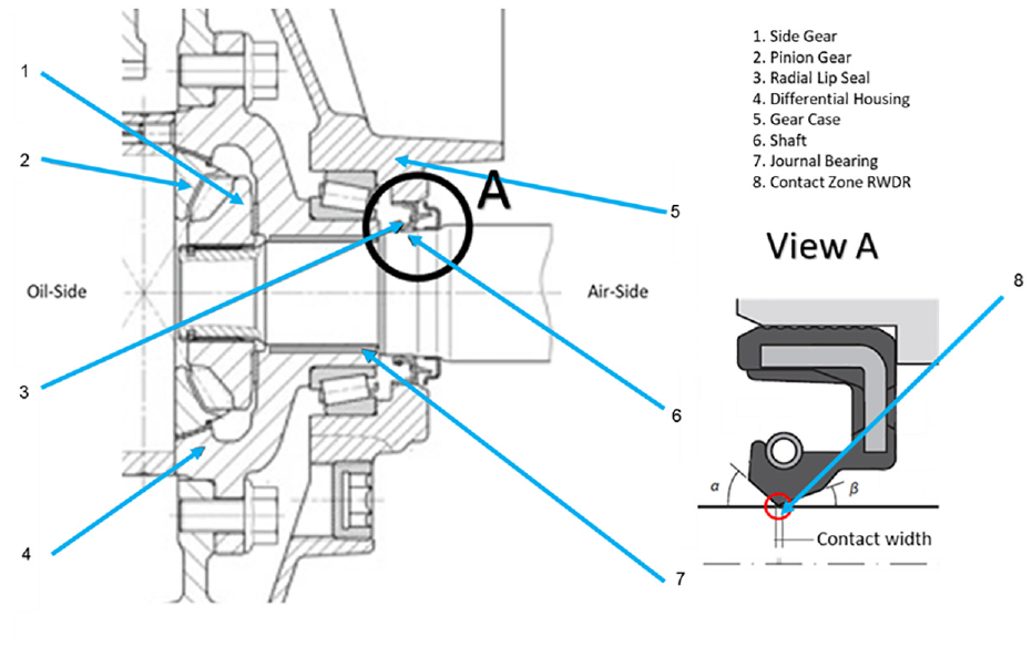
Assembly arrangement of RWDR in vehicular differential system of a typical passenger vehicle.
The system in Figure 1 comprises a side gear (1), a pinion gear (2), a radial lip seal (3), the vehicular differential housing (4), a gear-case (5), shaft (6) and a journal bearing (7). The shaft is form-fitted to the inner spline of the side gear via outer splines. The shaft is supported in the differential housing by a journal bearing. The sealing system is formed by a radial lip seal and the ground sealing seat of the shaft. The construction of the radial lip seal comprises an inner elastomeric component, a stiffening ring and a tension spring. The outer stiffening ring is pressed into the bore of the gearbox housing, statically pressing the radial lip seal against the differential housing. The inner elastomeric component consists of two sealing lips and a membrane.
The sealing lip of the rotary shaft seal, the subject of the current study, has a typical contact-width of 0.1–0.2 mm with the shaft surface, a contact angle α on the front side of approximately 45° and a contact angle β on the rear side of approximately 20°. In the case of the rotary shaft seal, the sealing lip is elastically suspended via a membrane, thus the sealing lip and the mating surface overlap. This arrangement creates a fitment pressure between the seal and shaft surface. The pressure is reinforced by a tension spring with a defined tensile force.
Figure 2(a) shows the main components of the test-rig. Through its flexible and modular design, the test-rig can be adapted to any vehicular geometry with minimal effort. All significant drivetrain components can easily be integrated into the experimental setup. All parts are mounted on an adjustable T-slot plate (9). The radial shaft seal is located in a specific flange (5) and sits on the sealing seat of the tested shaft (3). The shaft is supported by a vehicle-specific journal bearing mounted onto an adaptable flange (6). The tank of lubricant (7) is filled with the transmission fluid. A secondary test shaft support is provided by a vehicle-specific bracket (4). Position (6) shows the digital drive motor, connected to the rotating driveshaft via a clutch (2). Any leaked lubricant is collected outside the tank of oil.
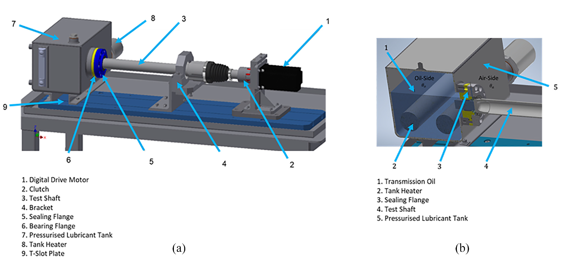
(a) Schematic representation of the test-rig design and (b) section through the sealing system.
Figure 2(b) shows a cross-sectional view through the sealing system. The lubricant filling-level (1) can be monitored continually. Both the tank heaters (2) are placed into the lubricant tank and interact with the integrated sensors. A crucial element of the test-rig is the exchangeable sealing-system (3), comprising a flexible two-part flange at the oil-side connected to a partially hollow shaft (4). Both these can be easily attached to the lubricant tank (5). The modular assembly of the test equipment ensures the ability to alternate between various vehicle sealing systems.
An image of the test-rig used in the current study is shown in Figure 3. The standard bracket is replaced by the OEM version to closely mimic the original mounting in the actual test vehicle. Furthermore, the rig is instrumented with various sensors. A circulation pump ensures constant lubricant recirculation to maintain a homogenous temperature level in the system.
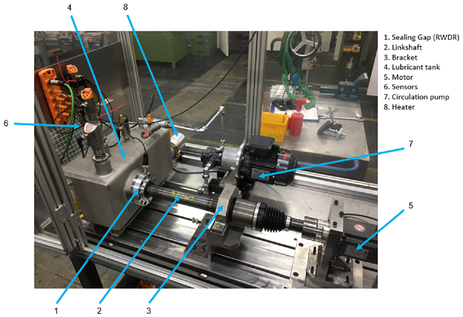
The test-rig.
The lubricant that percolates through the seal-shaft interface is collected using a blotting paper that can be weighed. The amount of leaked oil can then be measured precisely after any given test-cycle. The test-rig is equipped with various sensors measuring lubricant pressure, oil level and bulk lubricant temperature in the tank in real-time. The rotational shaft speed, the temperature in the close vicinity of the sealing point (arc of contact) and the resistive torque between the sealing lip and the shaft seat are also recorded. Two heating elements (8) are installed in the tank of lubricant, enabling precise adjustment and control of the sump temperature. Additionally, the temperature of ambient air is recorded and can be adjusted by an air conditioning unit. The control of the test-stand is ensured via programmable digital control, operated by means of an HMI (Human-Machine Interface).
Figure 4 shows a detailed view of the gearbox interface between the radial lip seal and the test shaft’s sealing seat. An original journal bearing (1) from the studied vehicle is mounted onto the bearing flange (2), supporting the bearing seat (3) of the test specimen (N.B. a vibration shaker is attached to simulate on-road vehicle ride’s transmitted vibration, not included in the current study). To prevent the lubricant from leaking from the sump, two static sealing rings (4) are mounted onto the RWDR flange (5) and the bearing flange. The sealing system, comprising the RWDR (6) and shaft sealing-seat, separating the oil-side and airside. A temperature sensor (7) monitors the oil temperature in the immediate vicinity of the sealing lip. Due to the relatively small distance between the sensor tip and the radial shaft seal, measurement of temperature is only possible from the immediate sealing zone. A measuring bar, consisting of a platinum thin film paired with a protective probe forms the needle body of the sensor.
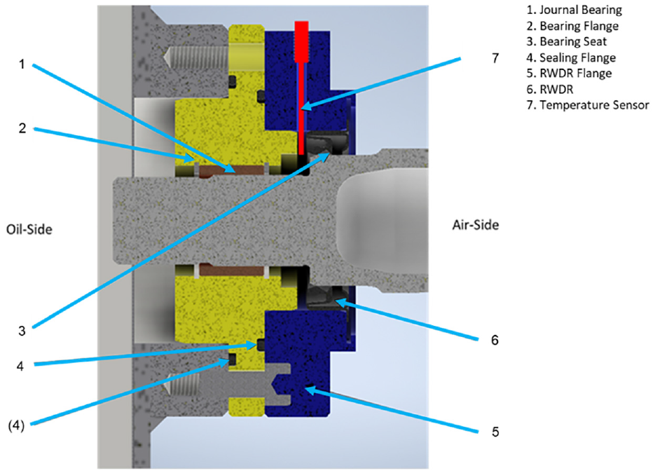
Seal conjunction at vehicular differential location in the test rig.
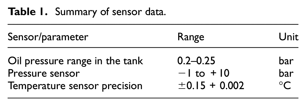
The principle of temperature measurement is based on the physical effect of the proportional change in electrical resistance at different temperature levels. With a constant electrical current supply, any drop corresponds to a change monitored by an integrated temperature transmitter. To ensure reliable detection of small temperature differences in the fluid surrounding the sealing lip of the rotary shaft seal, a class A sensor is used (Figure 5). The use of this type of sensor leads to a measurement accuracy of ±0.15 + 0.002°C as described in DIN/IEC 751 34 and DIN EN 60751 35 for class A and class B platinum temperature sensors. The lubricant temperature can be read directly via an integrated display. By using a programmable HMI, all the measured values can be visualised in real-time.
Figure 5(a) shows a control unit (1), 36 mounted to each sensor tip (2)–(3), ensuring uniform data acquisition and evaluation of different signals such as temperature, pressure or fluid level. Through an I/O-link as described by Drath and Rentschler, 37 the output signals of each sensor control unit acts as a communication interface between the sensors mounted in the test-rig and a central I/O-link master. 38 The sensor arrangement in the test-rig is shown in Figure 5(b). Position (1) shows the I/O-link master, which was used to network, process and transmit all the relevant sensor signals in a consistent manner to the HMI.
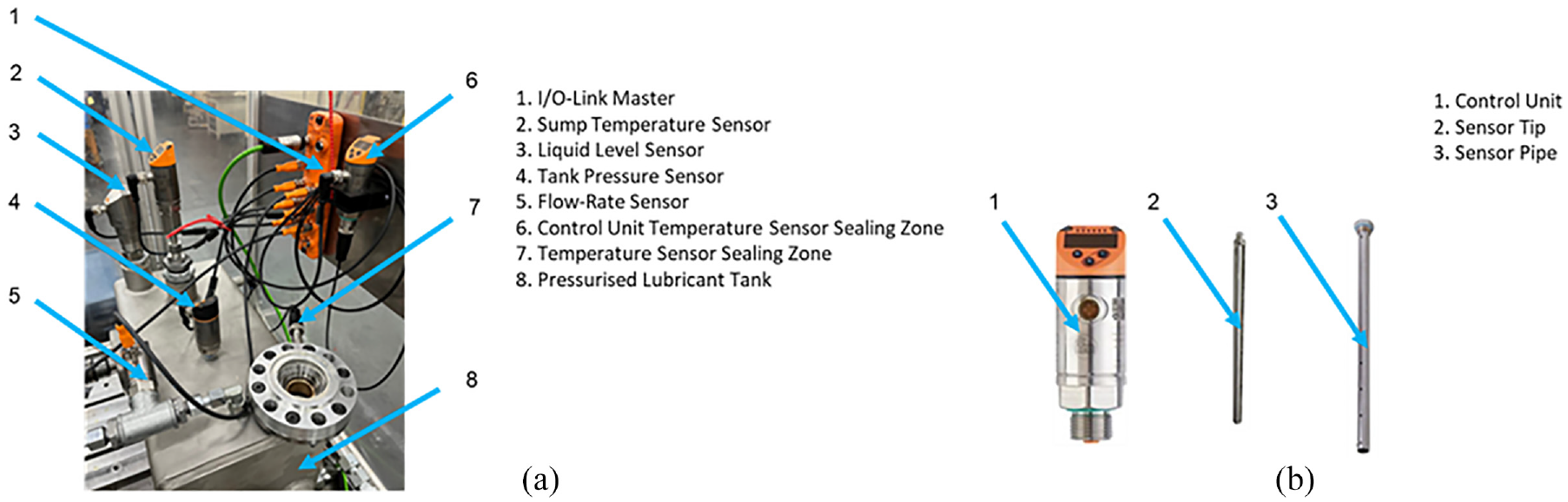
(a) Control unit with sensor arrangements and (b) different sensor tips.
A sensor control unit was used on each sensor tip (6), which transmits the relevant detected signals to the I/O-link master. The sensor shown at position (2) monitors the transmission fluid temperature in the sump (8). A specific liquid level sensor tip (3) 39 is used to constantly control the liquid level in the test-rig sump.
Due to a maximum possible fluid temperature of 65°C, a sensor with a coaxial probe is employed. The coaxial probe is composed of an outer tube and inside a centred measuring rod. The possible adjustment range of 150–2000 mm is flexibly adapted to the lubricant tank with a selected length of 150 mm. For this purpose, a minimum distance of 10 mm to the bottom of the lubricant tank is required. The height of the lubricant is measured by guided bidirectional microwaves. Electromagnetic pulses are emitted along the measuring probe, impinging on the medium stored in the vessel. Then, the pulses reflect back to the level measuring sensor. The microwaves are emitted at nanosecond intervals. As mentioned by Annuar et al. 40 the sensor system calculates the liquid level based on the time taken for the pulse to travel a certain distance.
To monitor the predefined pressure range of 0.2–0.25 bar in the lubricant tank, a parameterised pressure sensor (4), with a measurement range of −1 to + 10 bar is installed. The electronic pressure sensor can process two different measuring strategies: the switching state hysteresis, or the switching state window. Regarding the measuring task in the tank of lubricant, the hysteresis method is not applicable due to higher inertia and instability with changing pressure levels. The window method is advantageous due to the faster response times as the sensor switch is activated at the exact moment when the pressure value exceeds an upper tolerance. The same reaction is triggered when the pressure falls below a lower tolerance level. Consequently, the switch is also activated as soon as the pressure value is within the desired range. A summary of sensor characteristics is listed in Table 1.
Summary of sensor data.
A flow rate sensor (5) is placed to measure the flow velocity in the lubricant circuit of the test-rig. The flow sensor 41 operates according to a calorimetric measuring principle, simultaneously determining the flow rate and the lubricant temperature. The minimum flow rate should be maintained to ensure a homogeneous temperature level in the circulating lubricant. Secondly, the fluid temperature near the circulation pump can be measured. This additional function protects the pump from overheating the lubricant in case of any heating system malfunction. With the measuring assumption noted by Neto et al., 42 there is a constant temperature difference between a temperature sensor tip, periodically heated by a heating element and the surrounding unheated stationary medium. Only when the surrounding unheated medium begins to flow around the sensor a temperature difference occurs due to the absorption of thermal energy. The temperature difference increases proportionally to the higher flow velocity. To measure the lubricant temperature in the immediate vicinity of the sealing lip, a temperature sensor with a thin needle 43 is used (position 7 in Figures 4 and 5(b)).
Analytical thermal model
As already noted, contact temperature has a significant effect on the lubricant leakage from radial lip seals mainly through affected lubricant viscosity. In addition, excessive heat in the contact can reduce the lifespan of the lip seal itself. Therefore, it is important to be able to predict the contact temperature under various operating conditions with a reasonable degree of accuracy. It is, however, difficult to directly measure the temperature in the shaft-lip seal contact due to the very small contact dimensions (typically a few hundreds of micrometre square at most). In addition, any thermal probe in the contact can alter the actual state of the contact from its original configuration, particularly when there is an aim to investigate the correlation between temperature and surface topographical parameters. Therefore, the temperature of the contact is measured at some location in its vicinity as described in the previous section.
Details of a developed analytical model are described here. Some elements of the model are based on the original work of Feldmeth et al. 19 However, their original model is expanded and further enhanced for the purpose of the current study. The results from this model will be compared with the experimental measurements.
Determining the contact temperature
A schematic representation of the modelled sealing system including the various directional heat flow rates along the shaft is shown in Figure 6. Due to the proximity of the journal bearing to the sealing lip and the combined structure that holds them in place, it is assumed that the total heat generation rate,
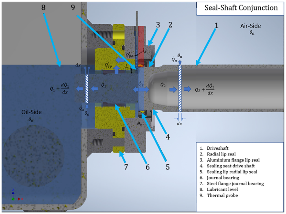
Schematic representation of the developed heat transfer model.
In addition, the contribution due to convection through leaked lubricant is expected to be negligible due to the small leakage flow rate. Therefore, it is expected that the generated heat due to friction in the contact,
Principle of conservation of energy dictates a thermal balance as:

where,
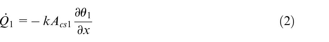

where, k is the thermal conductivity of the shaft material and
For an infinitesimal element of shaft, shown in Figure 6, the thermal balance results in the following relationships:


where,


where,
where,
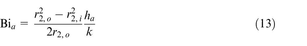
It is convenient to express the derived differential equations, based on the Biot number, which is essentially the ratio of thermal resistance inside the shaft body to that at its surface in each direction with the characteristic length being the ratio of the shaft’s volume to its surface area.
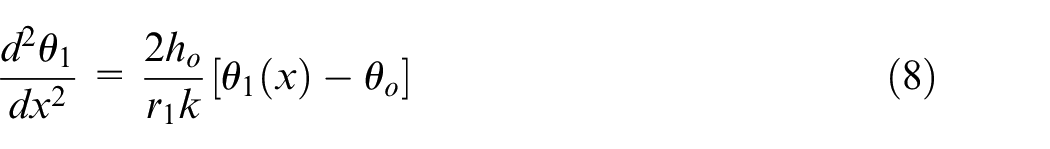
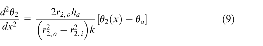
Thus, the differential equations take the following form:

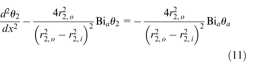
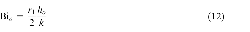
where, the Biot numbers for the oil and air sides are:
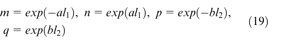
The resulting non-homogenous incomplete ordinary linear second order differential equations with constant coefficients have the solutions of the form:


where:
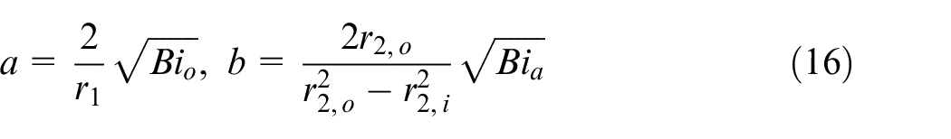
The constants

Implementing the boundary conditions yield:
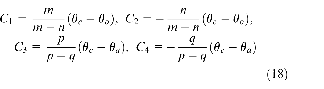
where:
Since the friction generated heat is essentially dissipated through air and oil adjacent to the shaft surface, the thermal balance can be stated as:
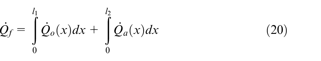
Replacing for the heat transfer rates from equations (6) and (7) results in:
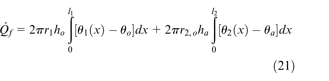
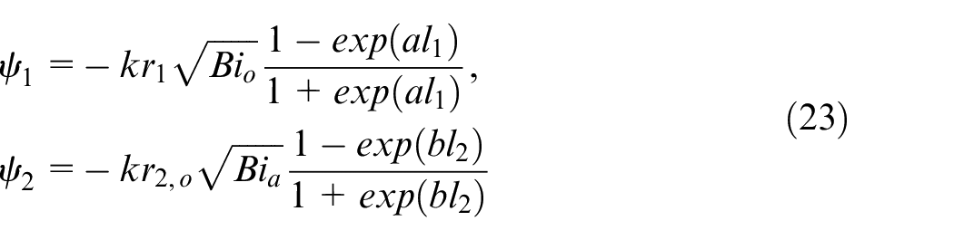
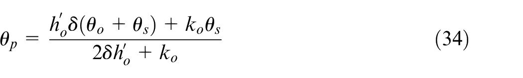
The temperature distributions can now be replaced from equations (14) and (15), and after carrying out the integration, equation (21) can be rearranged to obtain the contact temperature as:
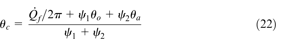
where:
Therefore, the temperature distribution along the shaft and in both directions can now be determined from equations (14) and (15).
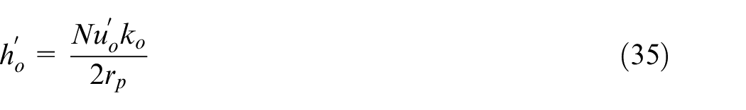
Determining the convective heat transfer coefficients
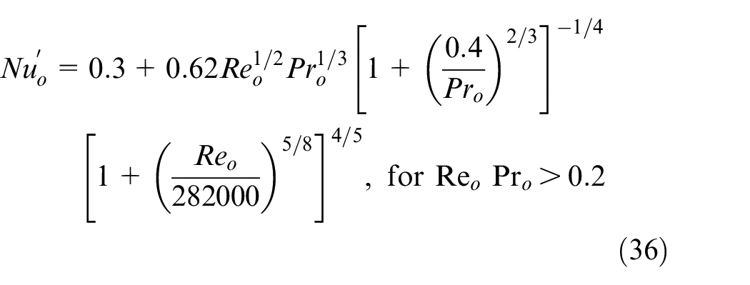
According to Wong, 44 the Nusselt number, including the effect of both natural and forced convections due to shaft rotation can be stated as:
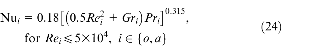
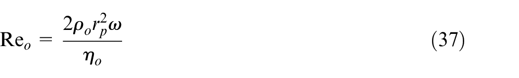
where, the indices o and a denote oil and air respectively. The corresponding Reynolds, Prandtl and Grashof numbers are:
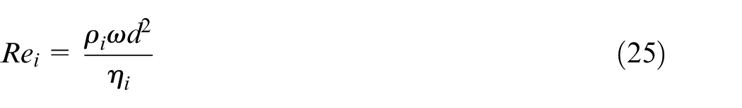
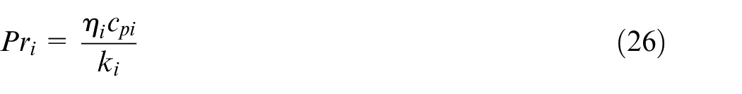
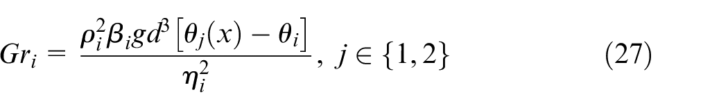
where,
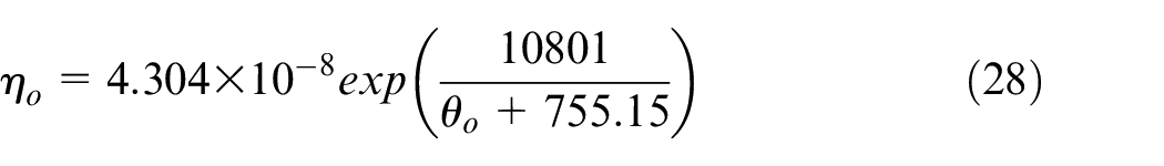
The variation of viscosity of oil with temperature is measured and the corresponding Vogel model is devised 45 :
The relationship between the viscosity of air and temperature is given by:

To examine whether the conditions studied here adhere to the requirement for the Reynolds number as stated in equation (24), variations of Reynolds number calculated for both air and oil side against a range of shaft speeds are shown in Figure 7. The validity of equation (24) for the air side can be justified for a range of speeds up to at least 3000 rpm, which is in line with the conditions studied here. These results also show that the conditions for the lubricant, with higher viscosity, would also remain well below the threshold Reynolds number specified in equation (24) for even higher speeds.
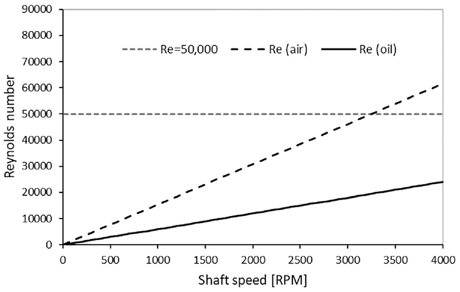
Variation of Reynolds’ number for oil and air interfaces with the shaft speed.
Figure 8 shows the contribution from natural convection for the calculated Nusselt numbers for both air and oil sides with an assumed temperature difference of 50°C between the fluid and the solid body. It is clear that the contribution of natural convection reduces significantly with increasing shaft speed. This is more so for the case of lubricant than air. Therefore, when considering the developed analytical thermal model for the cases where the shaft speed is below 500 rpm the effect of natural convection should be considered. It must be noted that if the temperature difference changes then the speed at which the effect of natural convection becomes important will also alter.
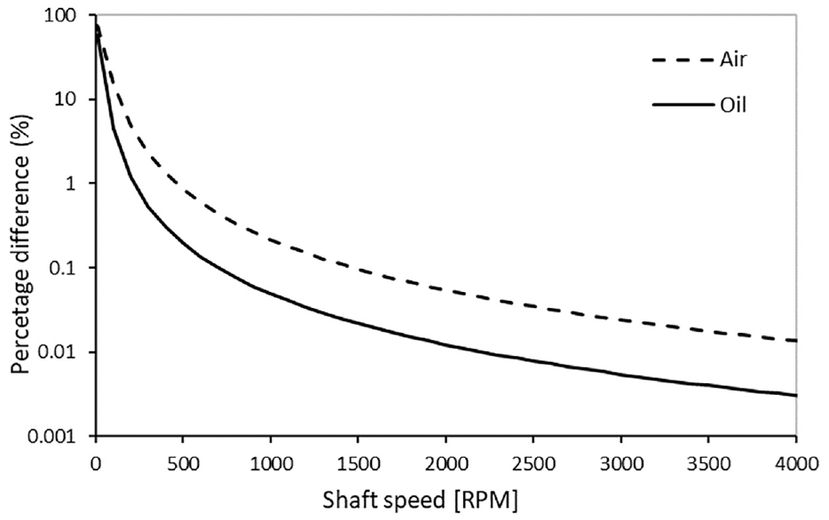
Percentage difference between the calculated Nusselt numbers with and without natural convection.
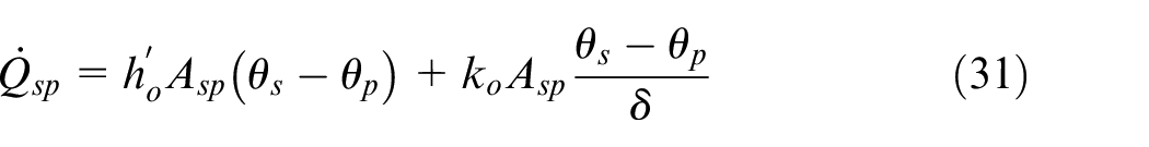
Determining the temperature at the location of the thermal probe
The thermal balance equation for the thermal probe can be written as:

where, the convected and conducted heat rates from shaft to the probe are:
The heat convected away from the probe to the environment (oil) is:

In the relationships above,

Thus, the temperature of the probe is obtained as:
The heat transfer coefficient for a cylinder is given by:
where, considering the thermal probe as a cylinder, the Nusselt number for turbulent crossflow of fluid over the surface of a cylinder is given by 46 :
where, the Reynolds number for the probe, exposed to the flow driven by the rotation of the shaft, is given as:
Results and discussion
The measured average torque and temperature for 50 Corundum ground and 50 CBN ground shafts are made. The variations of measured parameters with surface roughness characteristics of the used shaft are examined and compared with the predicted temperatures from the analytical model.
Measured friction torque
An example of the measured torque, rotational speed and temperature for the duration of an operation is shown in Figure 9. The rotational speed is kept constant during the operation. The break-in point (i.e. the culmination of running-in condition) is considered to be at the instance where the initial high torque drops to a minimum value. From this point onwards the torque remains largely settled (i.e. end of the transient response: no significant variations). The torque break-in point is considered to be at 337 min for the given example in Figure 9. In addition, the measured temperature at the immediate vicinity of the seal contact also stabilises relatively early during the test and remains steady thereon. To determine the average torque and temperature for each tested shaft, the initial transient part is excluded.
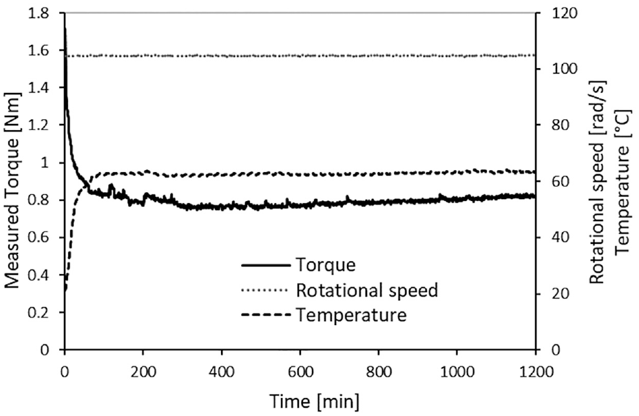
An example time history of key measured data from the test rig during operation.
The measured torque includes the frictional torque generated in the contact between the seal and the shaft, as well as the supporting bearings. To determine the frictional torque in the seal contact, a set of tests were conducted where the seal was removed. Therefore, the measured torque was expected to be representative of all the other frictional torques; generated by the bearings in the system. In total 100 shafts were tested, and the frictional net seal torque was determined. Figure 10 compares the net lip seal torques of the 50 CBN and 50 Corundum ground shafts.
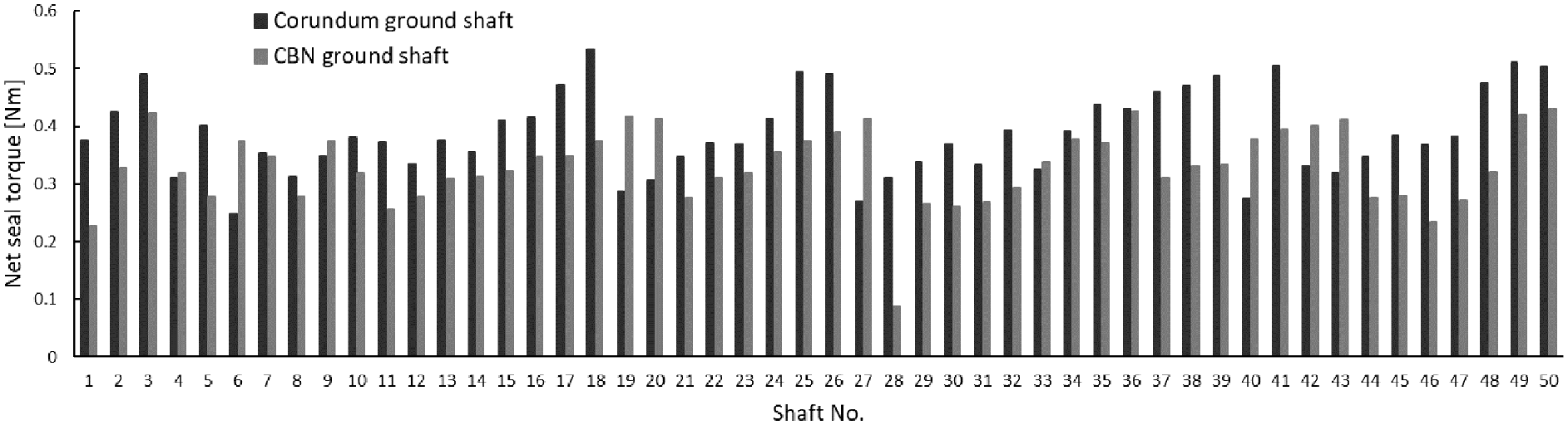
Net seal torque for Corundum and CBN ground shafts.
Measured temperature results
The measured average temperature values for the Corundum and CBN ground shafts are shown in Figures 10 and 11. The temperature at the location of the thermal probe is above the temperature of the lubricant in the sump for all the shafts. This indicates that in all cases, there has been some generated heat during the operation that has transferred to the thermal probe and caused its temperature to rise.
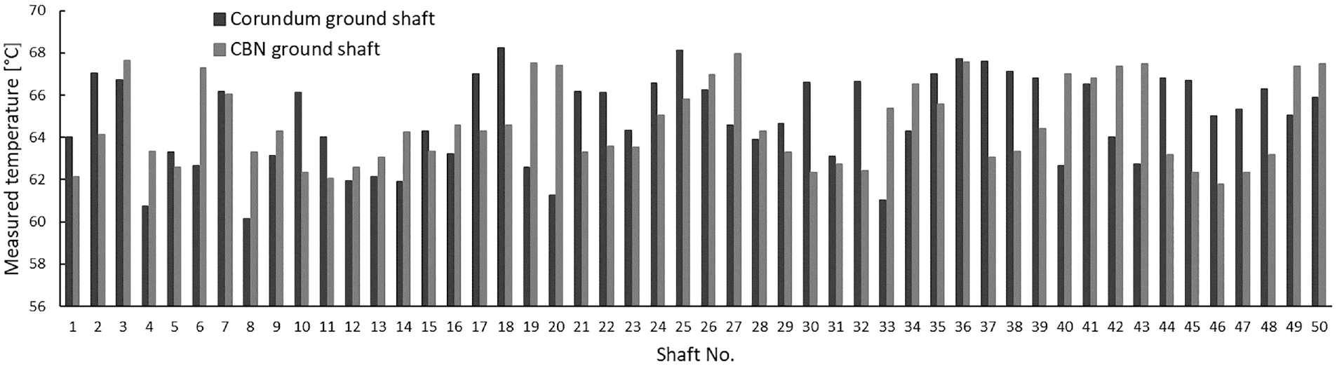
Measure temperature values for Corundum and CBN ground shafts.
In a previous study, Nomikos et al. 30 investigated the correlation between the measured leakage and the surface topographical characteristic data including, Ra, Rz and the shaft lead angle. Usually, standards define a range of acceptable values for these parameters and the shaft manufacturers strive to adhere to them. Those are used in various industries to ensure the quality and consistency of surface finishes. In Nomikos et al. 30 the possibility of existence of an appreciable correlation between the measured leakage and the skewness of the shaft surface roughness was observed. Therefore, it would be interesting to examine whether there would be any correlation between the measured temperature by the thermal probe and the surface roughness parameters. However, it must be noted that there is potentially a contribution from the journal bearing to the generated heat in the contact. This can potentially affect the generated heat and the measured temperature. Since the loading of the journal bearing and the operating conditions remains the same for all tests, under fully flooded hydrodynamic conditions the changes in the roughness of the shafts are not expected to have a noticeable effect on the generated friction in the journal bearing contact. Therefore, any variation of measured temperature with the roughness of the shaft should be influenced by the lip seal conjunction.
Correlation between the measured temperature and surface topography parameters
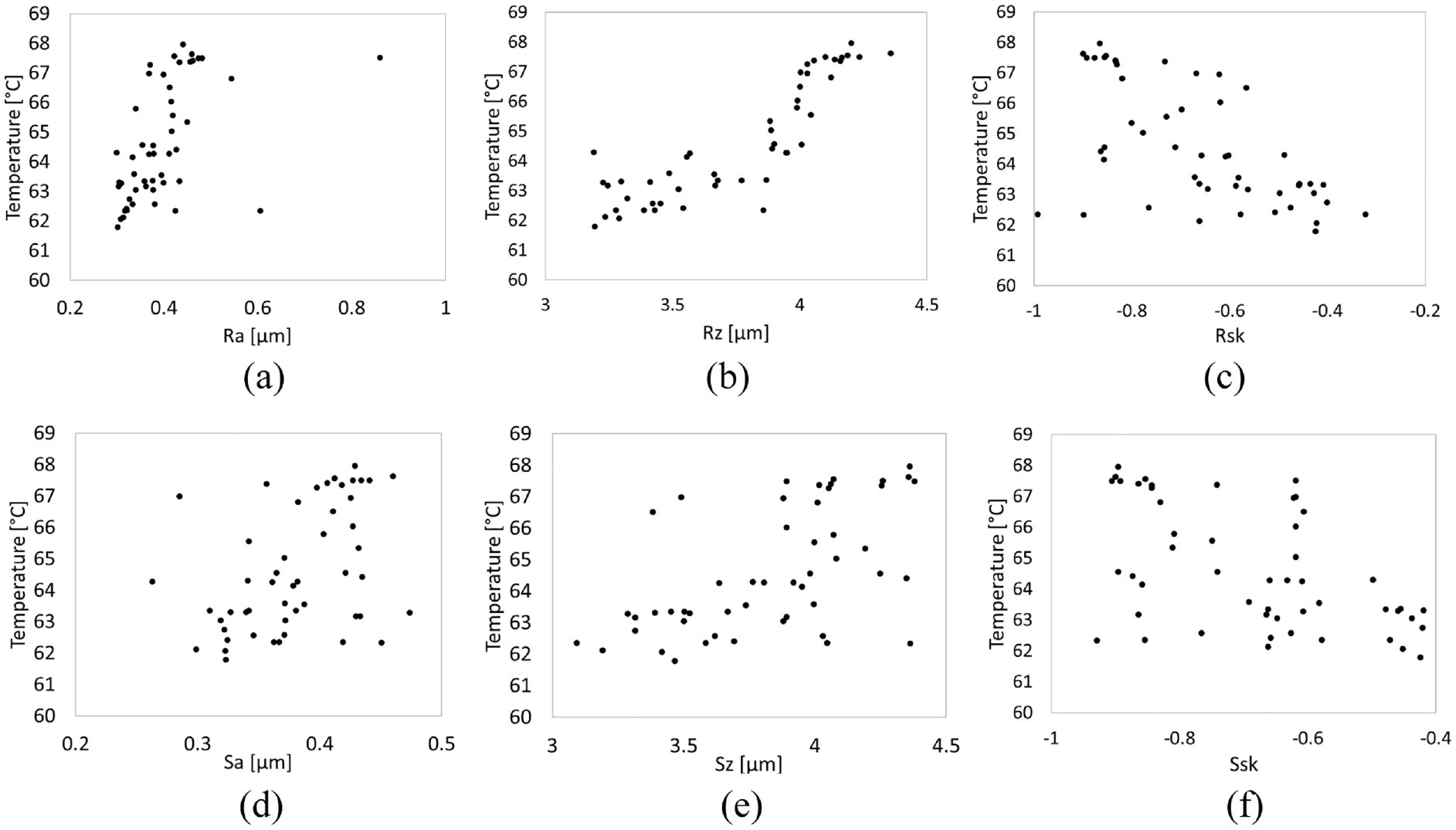
A comparison of the measured temperatures and surface parameters at the seal seat for the corundum-ground shafts is shown in Figure 12. Here the surface parameters Ra, Rz, Rsk, Sa, Sz and Ssk are considered. A correlation between the measured temperatures and surfaces is not apparent.
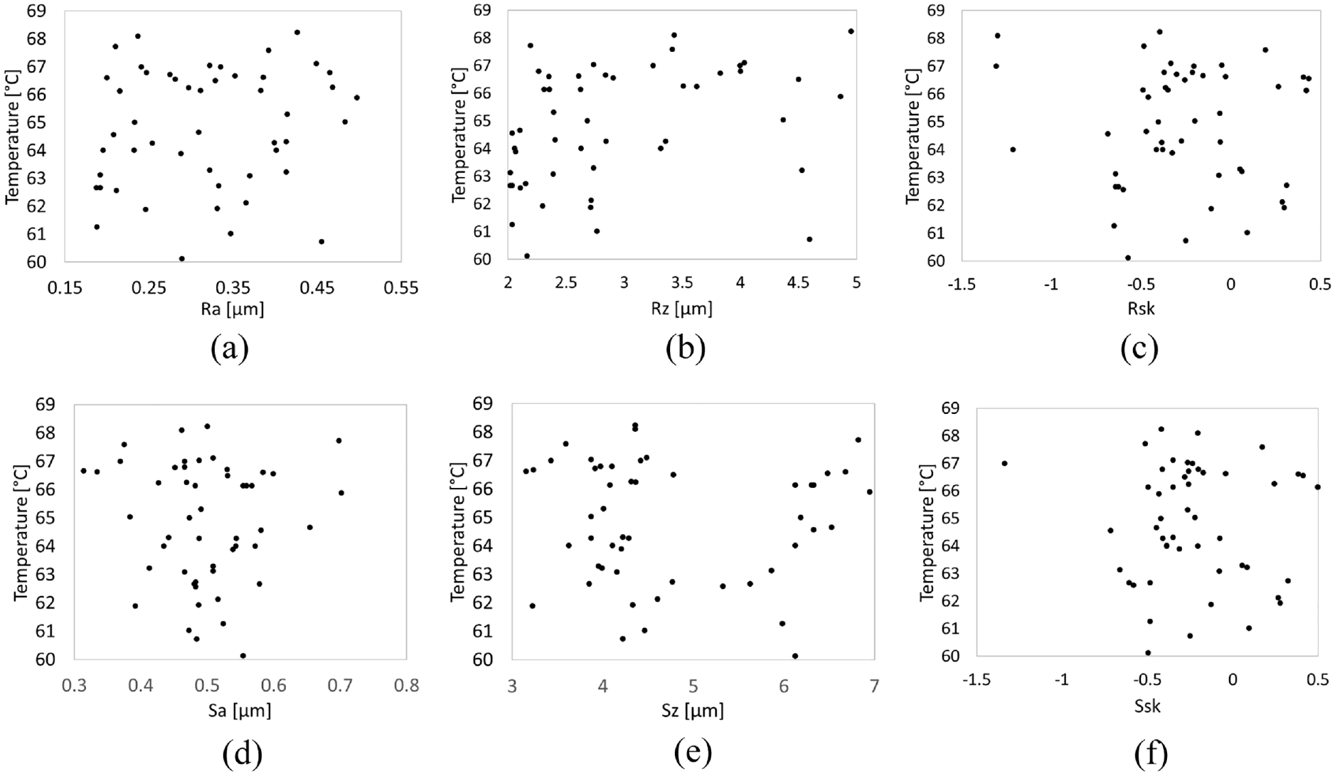
Measured temperature for corundum ground shafts against different shaft surface roughness parameters: (a) Ra, (b) Rz, (c) Rsk, (d) Sa, (e) Sz and (f) Ssk.
The variation of measured temperature roughness parameters for CBN ground shafts is shown in Figure 13.
Measured temperature for CBN ground shafts against different shaft surface roughness parameters: (a) Ra, (b) Rz, (c) Rsk, (d) Sa, (e) Sz and (f) Ssk.
Through applying Pearson’s correlation, it can be confirmed that there are not any significant correlations between temperature and surface roughness for corundum-ground bearing seats (see Table 2). In the case of the CBN-ground specimens, it can be stated, that there are some correlations between temperature and surface roughness parameters.
Pearson correlation coefficients for corundum and CBN ground shafts.
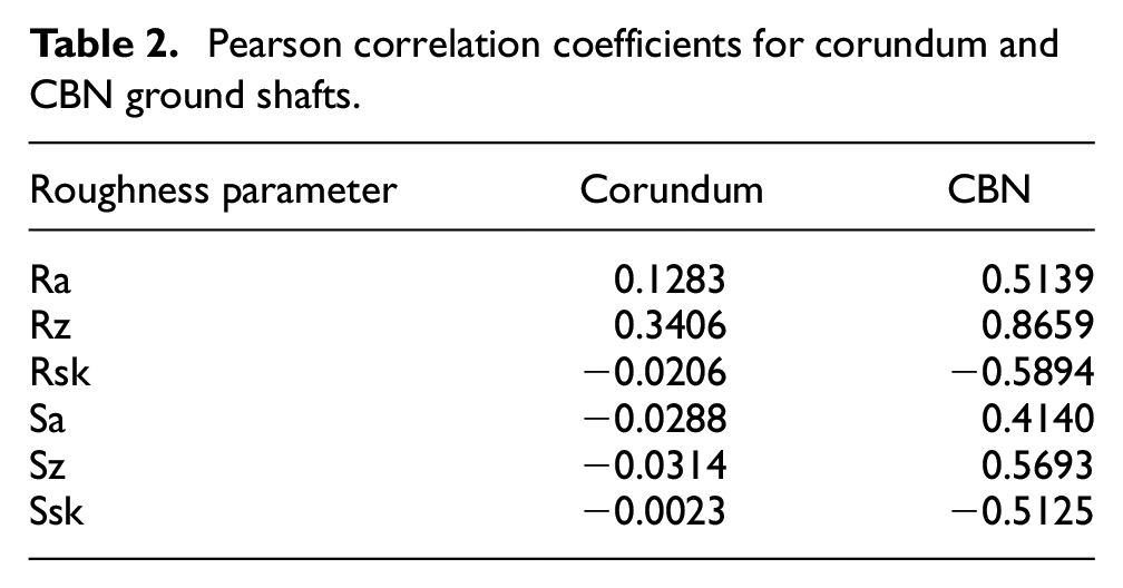
Out of all the investigated roughness parameters in Table 2 the correlation between the measured temperature and Rz is most noticeable. Higher values of Rz for shaft surface topography tend to result in higher temperatures. This can also be visually verified from Figure 13(b). In this case the temperature has the least correlation with the Sa parameter and the correlation with the other parameters, except Rz, are not significant. Virtually no leakage form CBN shafts was observed in Nomikos et al., 30 the stronger correlations between the roughness parameters and temperature in the case of CBN ground shafts is quite interesting.
The relationship between the measured temperature by the thermal sensor in the immediate vicinity of the seal and the resistive torque between the lip seal and the shaft surface are shown in Figure 14. In both cases a general trend of increasing temperature with torque is observable albeit more clearly in the case of CBN ground shafts. Calculating Pearson correlation coefficient results in a value of 0.567 for the corundum ground shafts and 0.707 for the CBN ground shafts. This indeed confirms the stronger correlation between the measured temperature and torque in the case of CBN shafts.
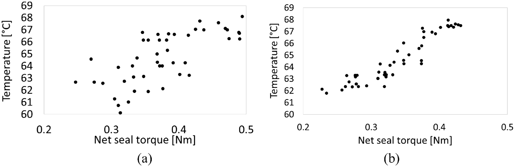
Measured temperature versus net seal torque for (a) corundum and (b) CBN ground shafts.
The examination of the measured net frictional torque against the Rz roughness values clearly shows that there is a stronger correlation between the torque and Rz in the case of CBN ground shafts than for the case of corundum ground shafts (Figure 15). In fact, the Pearson correlations coefficient for the corundum ground shafts against Rz roughness parameters is 0.773 whilst for the CBN counterparts it is 0.877. Therefore, the stronger relationship observed between the measured temperature for the CBN ground shafts and the Rz roughness parameter can be attributed to the stronger correlation found between the frictional torque and the Rz parameter. This indicates the potential dominant role and influence of the Rz roughness parameter on the generated frictional torque in radial lip seal contacts, and thus the generated contact temperature. In addition, the results also indicate that the correlation between Rz and temperature is weaker than its correlation with frictional torque. There are, of course, a larger number of physical parameters that influence the contact friction such as viscous shear of the lubricant film, whose viscosity is affected by temperature. Therefore, the correlations found should be considered as intertwined within the nature of parametric relationships.
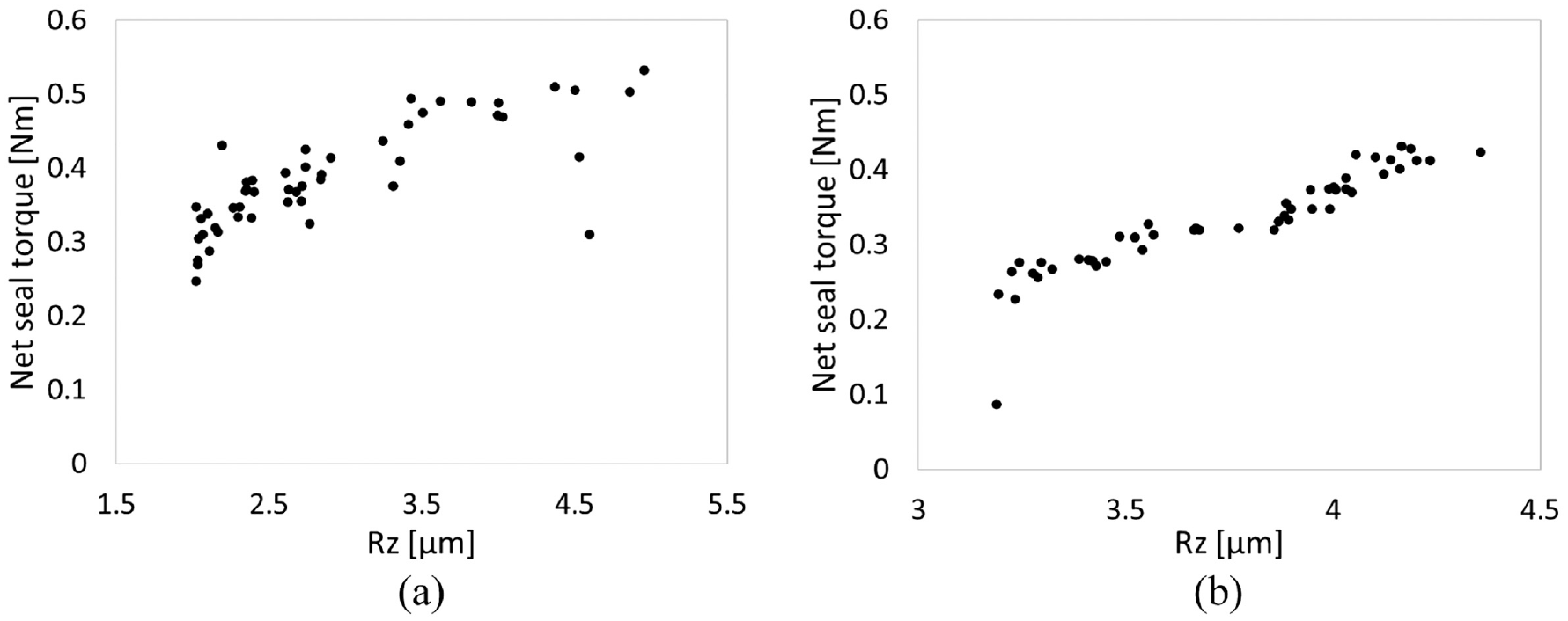
Measured net seal torque versus Rz roughness parameter for (a) corundum and (b) CBN ground shafts.
Use of detailed numerical methods which allow for inclusion of measured surface topographies may enable better understanding of correlations between measured temperature and Rz roughness parameter in the case of CBN shafts. However, further examination of the results for measured torque against other surface roughness parameters provides a further insight. As shown in Figure 16, a near linear correlation exists between the measured torque and shaft surface Rsk values in the case of CBN ground shafts. With increasing Rsk the torque also tends to rise. By comparing the results in Figures 15(b) and 16(b), it can be concluded that the rise in the Rz value in the case of CBN ground shafts is due the roughness profile being shifted towards higher negative skewness values. Therefore, a rise in the Rz value in the case of CBN ground shafts is associated with the surface topography having a greater concentration of deeper roughness valleys or troughs, as opposed to the roughness peak heights. This can explain the reason for higher measured seal torque in the case of corundum ground shafts in comparison to their CBN counterparts, having similar Rz values as can be seen in Figure 15(a) and (b). Thus, the near linear rise in the contact temperature with the Rz value in the case of CBN ground shafts is due to having a greater concentration of deeper troughs, whilst in the case of corundum ground shafts there is no such a correlation between the Rz and Rsk.
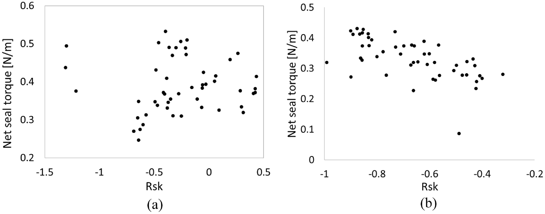
Measured net seal torque versus Rsk roughness parameter for (a) corundum and (b) CBN ground shafts.
Predicted temperatures
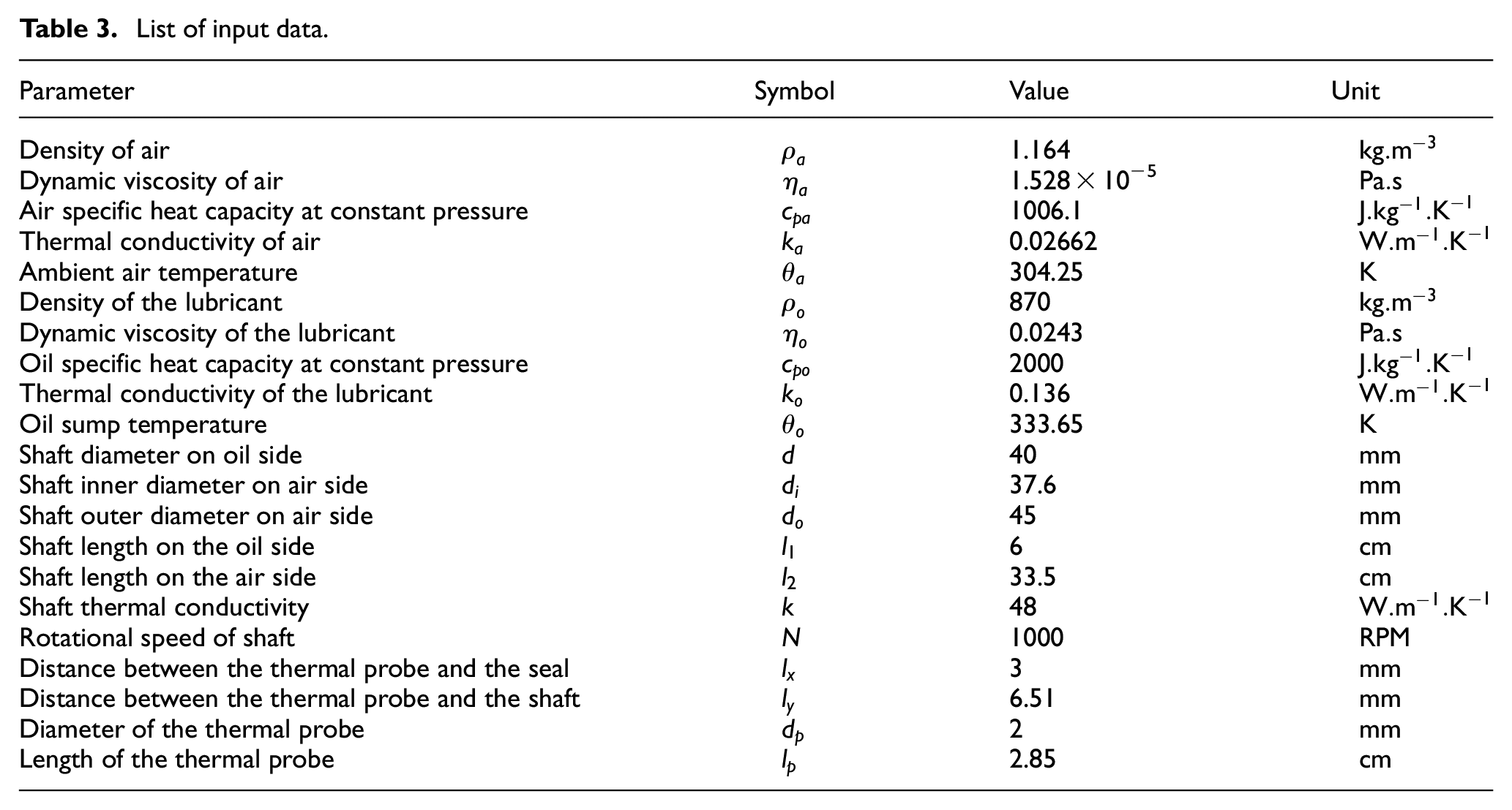
The measured temperature data is based on the recordings from the thermal probe in the immediate vicinity of the seal and shaft contact. The analytical model is developed in order to provide an estimation of the actual temperature in the contact. Table 3 list the data used in the development of the analytical model.
List of input data.
The predicted and measured temperatures at the thermal probe for Corundum and CBN ground shafts are shown in Figure 17. In addition, the predicted results for the seal-shaft contact temperatures are also shown. It can be seen that the predicted temperatures conform well with the measured data, particularly for the case of CBN ground shafts as shown in Figure 17(b). These results confirm the validity of the thermal model. Consequently, the predicted values for the contact can be regarded as reliable. From the results presented in Figure 17 it can be observed that for both corundum and CBN ground shafts the predicted contact temperature is higher, by several degrees Celsius, than the measured or predicted temperature at the probe. It must be noted that the trendlines in the Figure 17 are only provided for ease of tracking the data for each case. It must be noted that each individual data point is independent of the other data points in the provided results.
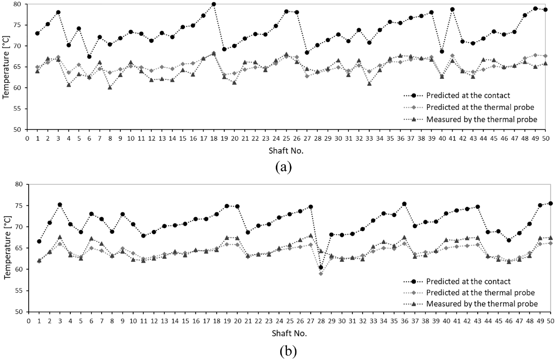
Predicted temperatures at the seal and shaft contact and measured temperature at the thermal probe location for(a) Corundum and (b) CBN ground shafts.
Predicted variations of temperature along the shaft towards the oil chamber and on the air side for both Corundum and CBN ground shafts are shown in Figure 18. The predicted temperatures drop more on the air side. However, this drop in temperature takes place at much longer distance along the shaft than on the oil side. The advantage of the current model is its ability in providing the level of temperature rise in the shaft at different locations. Therefore, if there is any need to add other components such as bearings along the shaft, the base operational temperature will be known for design purposes. The model can also act as a useful tool when developing a thermal network type model for the whole vehicular drivetrain for thermal management of the powertrain system; an example is highlighted by Sivayogan et al. 47
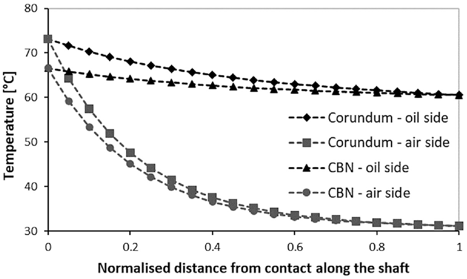
Examples of predicted shaft axial temperature variation for corundum and CBN ground shafts.
Conclusions
The paper reports on the use of a developed bespoke test-rig for measurement of temperature in the radial lip seal contact. The test-rig uses actual OEM parts from donor vehicles. The aim is to investigate potential correlations between the measured temperatures and surface topographical parameters of the shafts. Placing a thermal probe directly in the contact, apart from the technical challenges involved, could not provide the desired results. An analytical thermal model is therefore, developed to allow for predicting the actual contact temperature. The model is also validated by comparing the measured data with its predictions in the vicinity of the lip seal contact. The results from the analytical thermal model indicate the contact temperature in the sealing gap can be at least around 10%–15% higher than that measured at the location of the thermal probe, for the studied cases.
The measured temperature data from the test-rig shows little correlation between the measured surface topographical parameters and generated temperature in the case of Corundum-ground shafts. In the case of CBN-ground shafts a correlation is found between the Rz roughness parameter and temperature. In addition, a stronger correlation between the measured temperature and frictional torque is observed in the case of the CBN-ground shafts. It was shown that the stronger correlation between the frictional torque and Rz roughness parameter in the case of CBN-ground shafts could explain the correlation between measured temperature and Rz roughness parameter. Further investigations into the interaction of the lubricant with the surface roughness features and emergent performance parameters are required in order to provide an in-depth insight into the underlying physical mechanisms involved in the observed correlation.
Footnotes
Appendix
Declaration of conflicting interests
The author(s) declared no potential conflicts of interest with respect to the research, authorship, and/or publication of this article.
Funding
The author(s) disclosed receipt of the following financial support for the research, authorship, and/or publication of this article: The authors acknowledge the financial contributions of Neapco Germany towards work carried out in this project.