Current non-pneumatic wheel (NPW) designs with non-helical honeycomb spokes generally show too high cornering stiffness and thereby rapid saturation of the cornering force, which may lead to inferior handling and directional control of the vehicle, particularly under high operating speeds. The design concept of NPWs with symmetric helical honeycomb spokes is thus proposed in this paper. Three-dimensional (3D) finite element (FE) models of a honeycomb NPW with symmetric helical spokes configurations of different cell and helix angles were developed in order to fundamentally study its multi-axis and cornering stiffness properties under a constant normal load. The validities of the developed NPW models with 0° helix angle and three different cell angles were demonstrated through comparisons of predicted wheel responses with results available in published studies. 3D simulations were conducted under two design constraints in terms of identical cell-wall thickness and identical load carrying capacity. The results suggest that increasing helix angle results in significantly greater in-plane shear stiffness of the honeycomb spokes and thus could effectively yield higher longitudinal and vertical stiffness of the NPW. An increase in helix angle also causes lower lateral stiffness for the wheel designs with 15.8° and 31.5° cell angles resulting from increases in the out-of-plane compliance of the spokes, apart from the notably lower cornering stiffness, particularly when it is increased to 30° and 45°. The cell-wall thickness, however, shows positive influences on multi-axis stiffness of the honeycomb wheel but negative effects on its cornering stiffness. The design concept of helical honeycomb spokes could offer better vehicle performances than the current designs in terms of braking/traction and handling characteristics. These are particularly important for promoting applications of the NPW in high-speed vehicles.
A pneumatic tire is a toroid cord-rubber composite structure filled with pressurized air. This design has shown the ability to satisfy multiple performance demands of the ground vehicles such as comfortable ride, adequate traction for braking and driving maneuvers, and sufficient steering control and directional stability.1 The vehicles, however, could loss directional control in case of tire bursting or rapid air leakage, leading to potentially severe body injuries and property losses, particularly under high speeds scenarios. Therefore, a number of design concepts centering about airless or non-pneumatic wheels (NPWs) have been proposed in order to eliminate the safety risks related to the inflation pressure as well as the routine maintenances confronted with the conventional pneumatic tires.2,3
The reported NPW design concepts in general comprise a circular composite beam connected to the wheel rim via a number of solid spokes, which are discretely and uniformly distributed along the wheel perimeter, apart from the rubber tread.4–6 These NPW designs differ primarily in their spokes structures, the majority of which include the cellular spokes as in the honeycomb NPWs,4 the radial flexible spokes used in Tweels5 and the hinge spokes employed in the mechano-elastic wheels.6 In these NPW designs, the load applied on the rim is mostly suspended to the circular composite beam by the spokes away from the wheel/road contact region.5,7 This load carrying mechanism is analogous to that of the pneumatic tires, in which the load is primarily supported by the tensioned carcass cords anchored around the beads. Therefore, these designs are also expected to exhibit relatively lower vertical stiffness, lower mean contact stress and lower wheel mass per unit load carried, when compared to the traditional rigid wheels.5 Moreover, the spokes and the core layer of the composite beam used in the honeycomb NPWs and Tweels could be constructed from mouldable thermoplastic polyurethane, which shows relatively low hysteresis loss under cyclic loading and thereby lower rolling resistance and less fuel consumption.7,8 This could reduce greenhouse gas emissions of the vehicles, resulting in improved air quality, particularly in densely populated urban regions. Furthermore, NPWs are considered more recyclable than the pneumatic tires, which often end up in landfills and could take hundreds of years to decompose.9 In addition, the increased durability of the NPWs as well as their relatively simple manufacturing process could significantly reduce the environment impact of wheel production.10 These NPWs could thus be considered as environmentally friendly designs with improved fuel economy.
A number of recent studies have demonstrated that honeycomb NPWs with hexagonal cellular spokes of positive cell angles could provide sufficient load carrying capacity,11–13 low wheel/road contact stress with relatively uniform distribution,13 good ride quality,13 and low rolling resistance.11 Therefore, some studies evaluated chosen performance measures of honeycomb NPWs with certain hexagonal spokes configurations, using FE analyses. These include modal properties of the fully constrained NPWs with and without ground contact as well as vibrational characteristics and temperature distribution of the steady-state rolling wheels.8,14,15 The non-contacting NPW with fixed spindle revealed lowest natural frequency of 33.2 Hz corresponding to the torsion mode (rotational deformations about the wheel axis), while the pneumatic tires in general exhibit this in the lateral mode.16,17 Moreover, excessive amplitude peaks were observed in the response spectra of the rolling wheel, which occurred under excitation frequencies related to its forward speed and number of the discrete spokes. Furthermore, the core layer of the composite beam contributed about 70% to the total energy loss of the rolling wheel. In addition, a number of studies investigated the manufacturing of the honeycomb NPWs using molding18 and 3D printing.19,20
On the other hand, some studies have explored the effects of variations in geometric and material properties of wheel components on multiple performance characteristics of the honeycomb NPW, using finite element (FE) methods. The cell angle revealed negative influences on load carrying capacity or (equivalent) vertical stiffness of the NPW together with minimal effects on peak stresses observed in its tread and spokes.4,21,22 The NPW design with a higher cell angle thus necessitates spokes of greater cell-wall thickness so as to achieve identical load carrying capacity as its counterpart with a relatively low cell angle. This could lead to higher masses of the spokes and thereby increased rolling resistance of the wheel, apart from lower stresses in the spokes.4,22 Moreover, the cell angle showed only slight influences on the wheel/road contact area as well as the peak contact stress.21,23,24 Papageorgiou et al.25 performed a sensitivity study to evaluate influences of the cell dimensions on vertical stiffness, mass and peak contact stress of the wheel together with peak stresses in its outer ring and spokes. The results showed that tuning of these geometric parameters could yield improved performance measures of the wheel.
The response characteristics of the non-rolling and rolling honeycomb NPWs, when subjected to the normal loads, have been extensively investigated in the abovementioned studies, while only limited knowledge exists on those resulting from horizontal forces and moments excitations, which significantly affect braking/traction and steering performances of the vehicles. A recent study reported multi-axis and cornering stiffness properties of three honeycomb NPWs with varying cell angles but identical load carrying capacity, which was realized by tuning their corresponding cell-wall thickness, using the FE methods.7 The results suggested that longitudinal stiffness of honeycomb NPWs associated with relatively low cell angles are substantially lower than that corresponding to the chosen reference pneumatic tire with identical load carrying capacity and similar dimensions. The honeycomb NPWs, on the other hand, revealed considerably higher lateral and cornering stiffness than those of the reference pneumatic tire, which was attributed to their higher out-of-plane stiffness. Increasing cell angle, however, could help yield comparable longitudinal stiffness as that of the reference pneumatic tire, while its influences on lateral and cornering stiffness were comparatively slight. When a free-rolling pneumatic tire is subjected to a side force, it deforms and follows a straight line path at an angle with respect to wheel center plane or heading direction, which is defined as side slip angle.1 The cornering stiffness, defined as slope of the cornering force versus the side slip angle curve near zero side slip, is considered as a determining performance measure for directional control and stability of the ground vehicles. The NPWs have shown too high cornering stiffness leading the cornering force to saturate rapidly at very small side slip angles (≈1.5°), which can cause side sliding of the vehicles under maneuvers involving higher cornering force demand. This would also lead to adverse effect on handling and directional performance of the vehicle. Conversely, too low a cornering stiffness would lead to excessive side deformations of the wheel in order to reach the cornering force required for negotiating a turn. Similarly, the too low longitudinal stiffness of the NPWs with relatively small cell angles can lead to extremely large in-plane (vertical-longitudinal) shear deformations. These could cause higher stresses in the wheel resulting in reduced service life as well as poor braking/driving performances, apart from undesired sense of ride discomfort under longitudinal slip conditions. Therefore, it is vital to seek proper combinations of design parameters for the honeycomb NPWs, which could yield multi-axis and cornering stiffness properties comparable to their pneumatic counterparts.
Efficient parametric analyses using Taguchi and response surface methods have been conducted to study the effects of multiple design variables on multi-axis and cornering stiffness characteristics of honeycomb NPWs so as to establish design guidance.21,26 These considered spokes of different cell angles and two-factor interactions of important design parameters, namely, the thicknesses of the tread, core layer and the cell-wall, apart from the initial elastic moduli of their corresponding constituent materials. The results suggested that NPWs necessitated a higher cell angle in order to achieve similar longitudinal stiffness as the pneumatic tires of comparable sizes, irrespective of the other design factors considered. Moreover, variations in the design factors corresponding to honeycomb cell and tread could help achieve smaller lateral stiffness of the NPW, although the lateral stiffness was still notably higher than those of their pneumatic counterparts. This was owing to the considerably higher out-of-plane rigidity of the in-plane configuration of the honeycomb structures. In addition, tuning of the design factors, particularly those corresponding to core layer and tread, could help obtain comparable cornering stiffness as that of the pneumatic tires. However, these designs in general are coupled with thicker core layer and tread, which tends to lower longitudinal stiffness of the wheel and increase its mass and thus rolling resistance.
This study proposes a novel design concept for the honeycomb spokes, called “symmetric helical honeycomb spokes,” which could offer higher longitudinal stiffness for the NPWs, particularly those with the lower cell angles, together with additional reductions in their cornering stiffness. These could enhance the applicability of NPWs in high speed passenger cars. The effects of the proposed symmetric helical spokes on the stiffness properties of a honeycomb NPW are assessed considering spokes configurations of varying cell and helix angles. These include multi-axis stiffness of the stationary NPW as well as its cornering stiffness under 10 km/h rolling speed, when subjected a constant normal load (3 kN). For this purpose, comprehensive 3D FE models were developed for the honeycomb NPW with different symmetric helical spokes configurations so as to obtain their multi-axis force/moment-deformation and cornering force-side slip angle relations. The validities of the developed FE NPW models with 0° helix angle and different cell angles was then demonstrated through comparing the models’ responses including overall vertical deflections and cornering stiffness of the wheel as well as peak stresses in the cellular spokes with the reported results. The influences of cell and helix angles on the stiffness properties of the wheel were subsequently analyzed under two design constraints: (i) identical cell-wall thickness and (ii) identical load carrying capacity, so as to evaluate the relative merits of the symmetric helical spokes.
FE modeling of the honeycomb NPW
Three-dimensional (3D) FE models were developed for a honeycomb NPW, considering three different spokes configurations of varying cell angles (), in the order of 15.8°, 31.5° and 47.1°, respectively. These values were chosen to conform to those reported in Zheng et al.7 and Jin et al.,22 where some results are available for the verifications of the developed FE wheel models. The helix angle () associated with the spokes configurations of these three wheel models were subsequently increased from 0° to 45° in increments of 15°. This permitted analyses of the influences of on multi-axis and cornering stiffness properties of the wheel, while considering different .
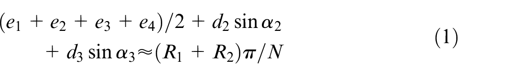
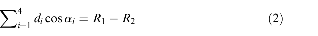
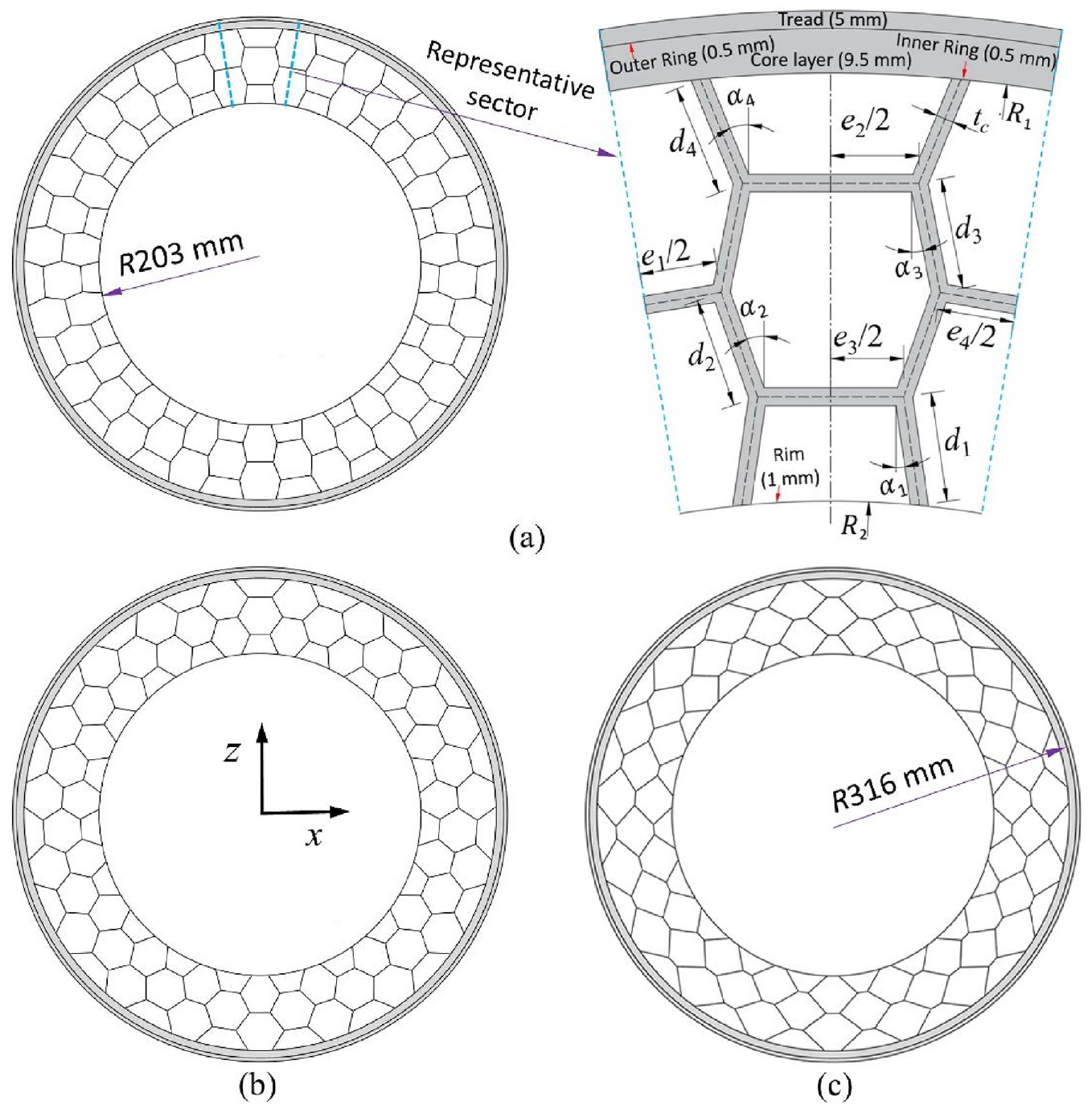
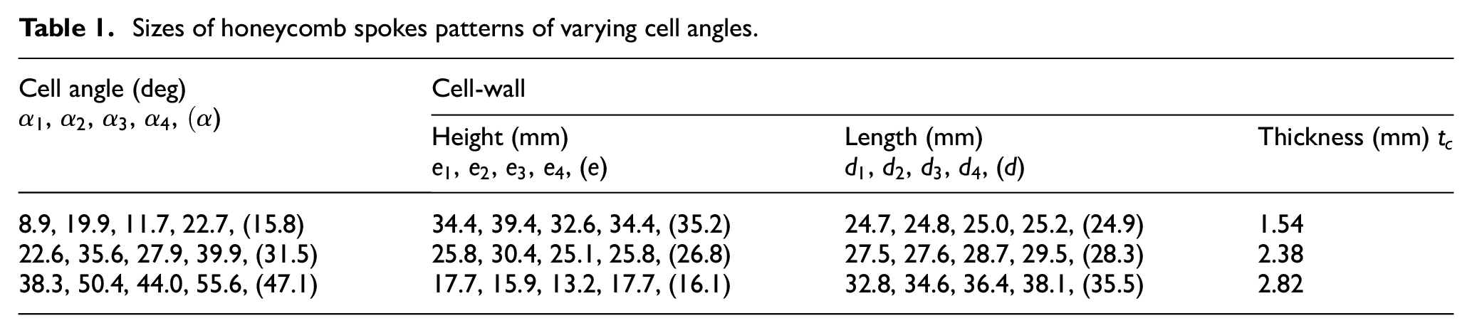
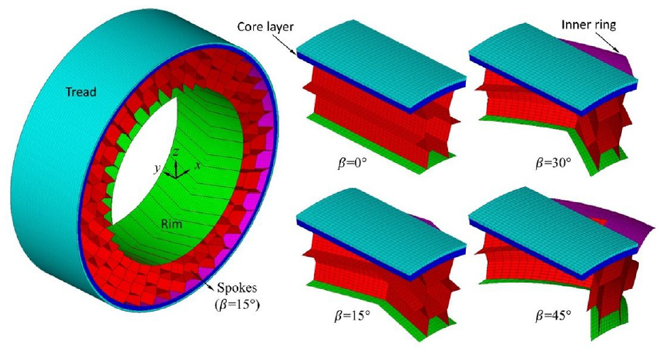
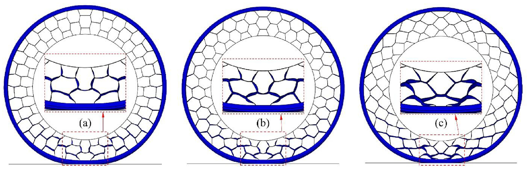
Figure 1 illustrates the NPW with three honeycomb spokes configurations (=0°) of different . Each wheel design is composed of the aluminum rim, cellular polyurethane spokes, sandwich/composite beam and the rubber tread. The sandwich/composite beam, also referred to as the shear ring, comprises two high strength steel rings sandwiching a polyurethane core layer. The dimensions of the wheel as well as its components including the spokes were taken as those of the designs reported in.7 These dimensions also roughly conformed to those reported in the study.22 Therefore, the radii of the wheel and the rim as well as the wheel width were confirmed as 316, 203 and 205 mm, respectively, as partly seen in Figure 1(a) and (c). Moreover, thicknesses of tread, two rings, core layer and rim were fixed 5, 0.5, 9.5 and 1 mm, respectively. It should be noted that the rim with negligible deformations was considered as a rigid body in the developed NPW FE models. Furthermore, the dimensions corresponding to the spokes of different in terms of cell-wall heights (), lengths () and thickness () are summarized in Table 1. In this table, , e and d represent the means of , and (i=1,..,4), respectively, which relate to the radii of the inner steel ring (=300.5 mm) and rim (=203 mm) as well as the number of spokes (N) along the wheel perimeter, as:
Honeycomb NPW with three spokes patterns of varying cell angles (): (a) = 15.8°, (b) = 31.5° and (c) = 47.1°.
Sizes of honeycomb spokes patterns of varying cell angles.
Cell angle (deg),,,,)
Cell-wall
Height (mm),,,, ()
Length (mm),,,, ()
Thickness (mm)
8.9, 19.9, 11.7, 22.7, (15.8)
34.4, 39.4, 32.6, 34.4, (35.2)
24.7, 24.8, 25.0, 25.2, (24.9)
1.54
22.6, 35.6, 27.9, 39.9, (31.5)
25.8, 30.4, 25.1, 25.8, (26.8)
27.5, 27.6, 28.7, 29.5, (28.3)
2.38
38.3, 50.4, 44.0, 55.6, (47.1)
17.7, 15.9, 13.2, 17.7, (16.1)
32.8, 34.6, 36.4, 38.1, (35.5)
2.82
It should be mentioned that is consistent with those reported in Zheng et al.7 and Jin et al.22
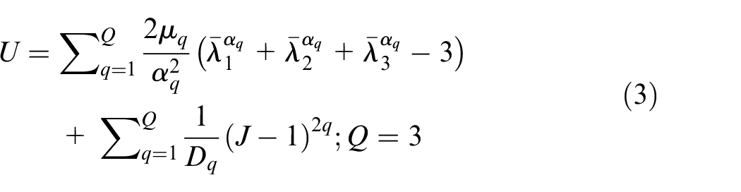
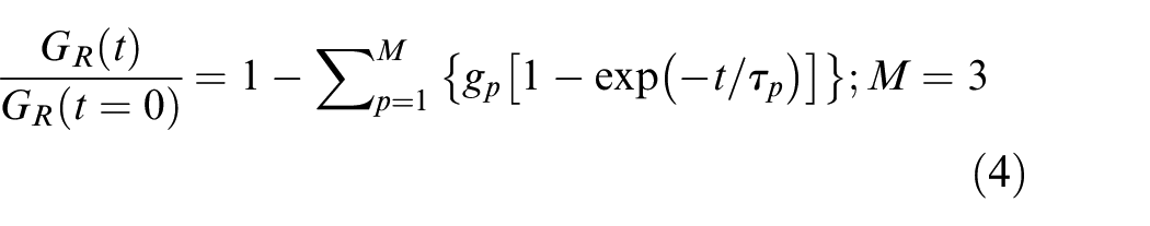
The mechanical behaviors of the elastic steel and aluminum were modeled using linear elasticity theory, while those corresponding to the hyper-viscoelastic polyurethane and rubber were described using Ogden strain energy potential as well as Prony series, as:
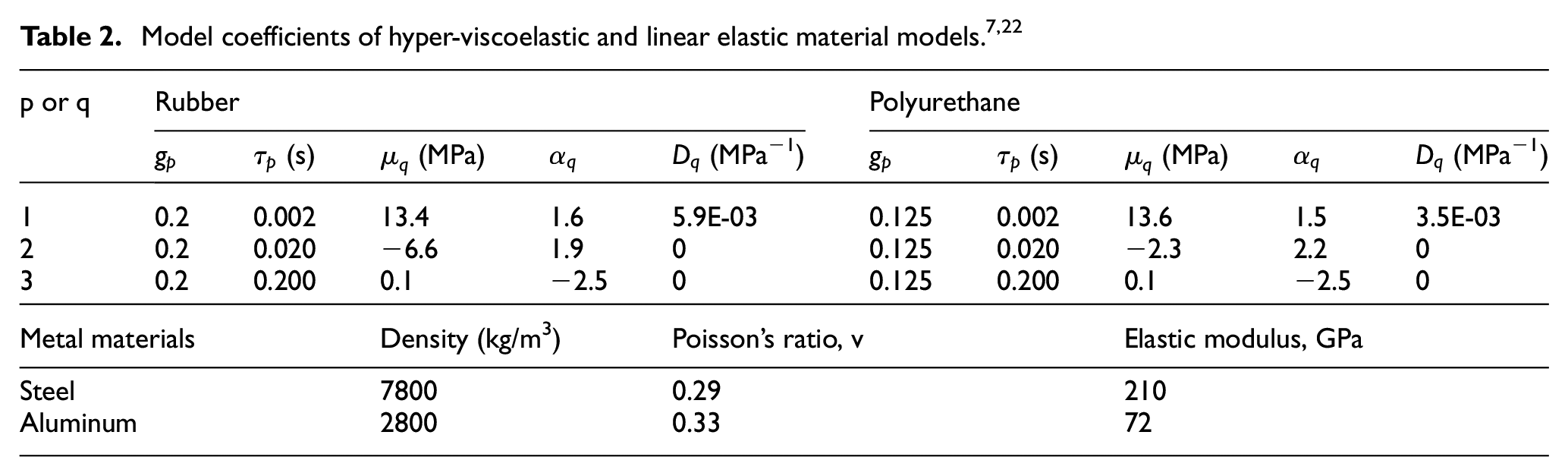
where U denotes the strain energy density, while , and are model parameters that affect the initial shear and bulk moduli of the materials. J represents elastic volume ratio, and , and are deviatoric principal stretches. represents the time varying shear relaxation modulus, while and (p = 1,.., M) are pth Prony series parameters. These material model parameters were taken as those reported in,7,22 which were identified using stress-strain and strain- or stress-time relations obtained from measurements,27 as presented in Table 2 together with Poisson’s ratios and Young’s moduli for the elastic materials.
Model coefficients of hyper-viscoelastic and linear elastic material models.7,22
p or q
Rubber
Polyurethane
(s)
(MPa)
(MPa−1)
(s)
(MPa)
(MPa−1)
1
0.2
0.002
13.4
1.6
5.9E-03
0.125
0.002
13.6
1.5
3.5E-03
2
0.2
0.020
−6.6
1.9
0
0.125
0.020
−2.3
2.2
0
3
0.2
0.200
0.1
−2.5
0
0.125
0.200
0.1
−2.5
0
Metal materials
Density (kg/m3)
Poisson’s ratio, v
Elastic modulus, GPa
Steel
7800
0.29
210
Aluminum
2800
0.33
72
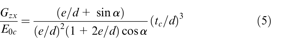
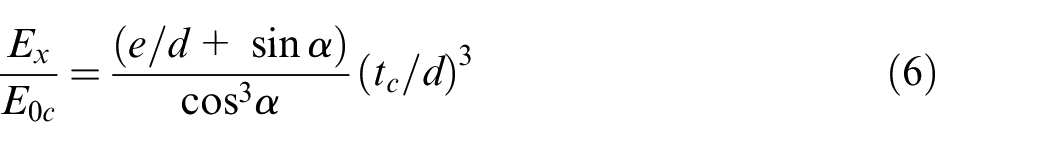
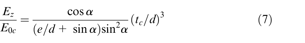
In the linear region, the in-plane (x-z plane in Figure 1) effective shear and elastic moduli of a 2D honeycomb cell, which relate to its mean dimensions (, d, e and ) as well as the initial elastic modulus () of its constituent material (polyurethane), could be approximately evaluated using the following relations4,28:
where denotes the effective shear modulus of the 2D spoke, while and are its effective elastic moduli in x- and z- directions, respectively. These effective moduli of the 2D spoke significantly influence the in-plane stiffness properties of the wheel.
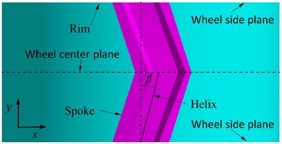
The FE models of the NPW with honeycomb spokes configurations of varying and were constructed. As an example, Figure 2 depicts one periodic or full wheel model with 15° helix angle together with four sector models with varying , considering =15.8°. The 2D cross-sectional elements of the tread, outer ring and the core layer of a representative sector (Figure 1(a)) were initially copied and dragged along the y-direction from the side plane of the wheel to its center plane, while those of the inner ring, spokes and the rim were duplicated and extruded along the helices of varying , as seen in Figures 2 and 3. This could ensure that the elements of the inner ring are connected to those of the rim by the spoke elements via shared nodes. The other components, however, were assembled together and adhered to the inner ring using surface-to-surface tie constraint. These elements were subsequently duplicated and reflected with respect to the wheel center plane to build the sector or partial models. Each of these sector models was copied and revolved about the wheel axis so as to generate corresponding full model of the entire wheel, using the symmetric model generation feature incorporated in ABAQUS software.29 This approach allowed for efficient modeling of the dynamic interactions between a steady-state rolling wheel and the non-deformable terrain.30–32
Full wheel model with 15° helix angle () and four partial models with different , considering 15.8° cell angle.
Spoke developed on wheel rim considering = 15.8° and = 15°.
More detailed information about the development of the three FE wheel models for non-helical cell configuration (=0°, =15.8°, 31.5° and 47.1°) in terms of element selections, wheel/ground contact and interactions as well as grid convergence studies have been recently presented in Zheng et al.7,21 The dynamic and static friction of coefficients were taken as 0.75 and 0.80, respectively, so as to represent the sliding and sticking interactions of the wheel with the dry asphalt road.1 It should be noted that the nearly optimal element sizes, which were determined from grid convergence studies, could ensure converged wheel responses with minimized computational cost. The out-of-plane and in-plane wheel responses considered in grid convergence studies included the peak stresses in the cellular spokes and the overall wheel vertical deflections under various normal loads, apart from the wheel cornering force at 10 km/h forward velocity and 0.5° side slip angle. Similar element sizes were also applied to the wheel models with other spokes configurations of =15°, 30° and 45°.
Method of analyses
The stiffness properties considered in this study include the multi-axis stiffness and the cornering stiffness of the honeycomb wheel under stationary and rolling conditions, respectively. To derive these stiffness values, the contact of each NPW model with the fully constrained rigid road was initiated by displacing the wheel vertically. A gradually increasing vertical force was subsequently applied to the rim center until the desired normal load level (3 kN) was achieved. Unbalanced contact forces and thus potential convergence difficulties could be avoided using this two-step loading approach.29 The ratio of the normal load (3 kN) and the resulting overall vertical deformation of the NPW is defined as its vertical stiffness (). Subsequently, the rigid road was translated along x- or y-axis or revolved about z-axis (Figure 2) so as to yield longitudinal and lateral force-deformation as well as yaw moment-deformation properties. The static coefficient of friction was taken as 0.80, as stated above. The longitudinal () and lateral () stiffness of the wheel were assessed within relatively small deflection ranges, in the vicinity of 0–1 mm for both the directions. In a similar manner, the yaw stiffness () was estimated within 0–0.2° yaw rotation range.
When a straight-line rolling honeycomb wheel is subjected to a side slip angle, it deforms and rapidly reaches the steady-state motion. The governing equations of motion of this rolling wheel FE model could be solved by means of explicit or implicit time integration methods so as to derive its transient (time-dependent) responses.29 These direct-integration methods, however, in general necessitate extremely small time increment size or a large number of iterations so as to accurately predict cornering force responses of the wheel.33–35 These could thus cause excessive computational demands, particularly for the large size FE models. Moreover, these methods need repeated simulations for each side slip angle to obtain corresponding steady-state cornering force, resulting in considerable additional computational cost.
In this study, an alternate approach is adopted to derive steady-state cornering force and deformation responses of the rolling NPW model under side slip conditions directly without consideration of its prior transient states. This was realized using the steady-state transport analysis feature in ABAQUS/standard.29,36 Unlike the above-stated transient analyses, this approach uses a frame of reference fixed to its axis of revolution (y-axis) and traveling with the wheel. This allowed for representation of the wheel rotation, in a Eulerain manner, by the transport of the constituent materials through the stationary mesh, while deformations of the wheel could be described using the Lagrangian approach. Moreover, the cornering force response of the NPW model at each incremental side slip angle corresponds to a steady-state solution. Therefore, the cornering forces corresponding to varying side slip angles can be derived using only one steady-state transport simulation. In addition, this efficient approach could offer improved accuracy when predicting cornering force characteristics under large side slip conditions.33
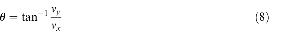
Following the static loading of the honeycomb NPW model, a constant forward velocity was specified for the above-stated traveling frame of reference, while an angular velocity was assigned to the transporting materials. This represents the constant forward speed motion of the wheel with braking/driving torque around its revolution axis. Tuning this angular velocity could yield zero torque, which corresponds to the straight-line free rolling solution. Subsequently, an additional lateral velocity, which gradually increases during the analysis, was specified for the traveling frame of reference in order to obtain cornering force responses at different side slip conditions. The side slip angle () represents the angle between the directions of travel and the wheel heading, which relates to forward () and lateral () velocity components of the wheel, as:
It should be noted that owing to the considerable difference between stationary and rolling frictional stresses, the abovementioned static load simulation was repeated, however, with zero friction coefficient, which was subsequently increased to 0.75 for the steady-state transport analyses. These could ensure smooth transition of frictional stresses and therefore eliminate potential convergence problems.29,33 Moreover, the nonlinear governing equations of both stationary and rolling wheel models were solved using Newton-Raphson’s method. Furthermore, the default convergence criteria which could offer relatively accurate solutions at each iteration or increment was used in this study.29
Model verifications
The validities of the developed FE models for the three honeycomb NPWs with spokes of three different cell angles (=15.8°, 31.5° and 47.1°) but without the helix (=0°) were initially verified by comparing their static responses with those corresponding to the reported designs,22 which employed same material properties as well as similar wheel and components dimensions. The peak difference in the dimensions of each wheel in the present study and its counterpart of identical cell angle, as reported in Jin et al.,22 is about 6%, with the exception of the cell-wall thickness. The cell-wall thickness of each design was tuned to yield about 190 kN/m vertical stiffness () to conform to that of a reference pneumatic tire (205/55R16). The vertical stiffness of the reported wheel designs22 (≈202 kN/m), however, was slightly higher. It should be stressed that the static responses presented in22 were also obtained using the FE methods. These FE models, however, were validated through comparisons of dynamic deformations of the cellular spokes with those observed in a prototype honeycomb wheel of comparable structure.22 These static responses included peak stresses in the cellular spokes and overall wheel vertical deflections, considering normal loads varying from 2 to 4 kN.
Additional models’ verifications were also conducted by comparing their cornering force responses obtained under rolling conditions with those of the reported designs,7 which used identical wheel dimensions and material properties. The dynamic responses of each wheel model with different and normal loads (2–4 kN) were derived using the steady-state transport analysis feature, considering 10 km/h constant forward velocity and side slip angles varying from 0 to 5°. The cornering force gradient within relatively small side slip angle range (0–0.2°) is defined as cornering stiffness () of the NPW. It should be pointed out that the cornering force responses reported in Zheng et al.7 were obtained using the explicit time integration techniques. In Zheng et al.7 identical boundary and loading conditions were imposed on the FE models of the honeycomb NPWs and a pneumatic tire. The validity of the FE model of the pneumatic tire, however, was demonstrated by comparing predicted and measured load-deflection and cornering force characteristics. This added the validity for the FE models of the honeycomb NPWs in Zheng et al.7 which offer data for verifications of the wheel models in the present study.
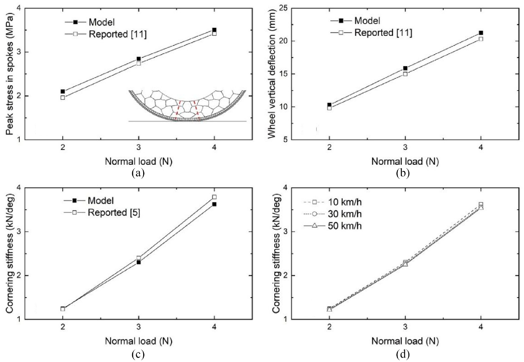
For example, Figure 4(a) and (b) depict comparisons of model-predicted and reported static responses, considering 31.5° cell angle. Reasonably close agreements are observed between model-predicted and reported overall vertical deflections of the wheel and peak stresses in the cellular spokes, with maximum differences of 5.8% and 7.2%, respectively, for the normal load range considered. These deviations may be due to small differences in components dimensions of the wheels, as stated above. Moreover, the peak stresses in Figure 4(a) invariably occurred in the cellular spoke close to center region of the wheel/road contact patch, irrespective of considered. This is primarily owing to their considerably higher strain resulting from compression deformations, as compared to the spokes away from the contact patch, which undergo tension deformations along the radial direction of the wheel. The results in Figure 4(c) suggest close agreements between reported and predicted cornering stiffness () for the normal load range considered, with less than 4.1% difference, which occurs for the 4 kN wheel load. The differences may be attributable to the fact that the cornering force characteristics of the reported designs were derived using verified FE models with explicit time integration technique. Similar levels of agreements were also noted for the NPW FE models with =15.8° and 47.1°. Therefore, these wheel models could be viewed as valid with regard to the available information, and be employed to investigate the dependences of wheel’s stiffness properties on the proposed symmetric helical spokes by varying its helix angle.
Comparisons of model-predicted: (a) peak stress in the spokes, (b) overall vertical deformation, (c) cornering stiffness of the NPW with reported data and (d) Influences of forward velocity on wheel cornering stiffness (cell angle: 31.5°; normal loads: 2–4 kN).
In order to investigate the dependence of the cornering stiffness properties of the honeycomb wheel on the forward velocity, steady-state transport simulations were conducted for these three wheel models, considering additional two forward velocities (30 and 50 km/h). For instance, Figure 4(d) depicts variations in of the wheel model (=31.5°) with varying forward velocities, under different normal loads. Less than 2.4% decrease in , which occurred at higher wheel normal load of 4 kN, was observed with increasing forward velocity, as in the case of the pneumatic tires.1 The results obtained for the NPW FE models with =15.8° and 47.1° also revealed similar trends. Therefore, the forward velocity was limited to only 10 km/h for subsequent studies on cornering stiffness properties of the rolling wheels.
Results and discussion
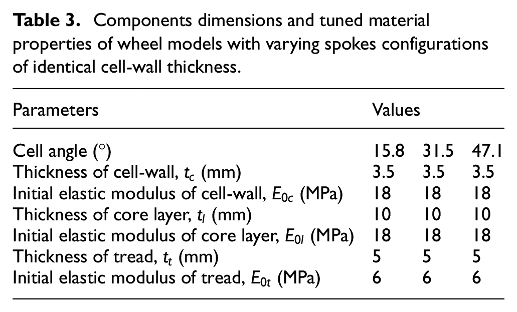
FE simulations were conducted for honeycomb wheel models with symmetric helical spokes of different cell () and helix () angles so as to explore their influences on multi-axis and cornering stiffness properties of the wheel, under a constant normal load (3 kN). These wheel designs with different spokes configurations were initially assigned with identical cell-wall thickness (). It needs to be noted that in the absence of helix angle (=0°), the reported material properties for the polyurethane and the rubber (Table 2) resulted in extremely high cornering stiffness of about 2300 N/deg for the three wheel models (=15.8°, 31.5° and 47.1°) under 3 kN normal load and 10–50 km/h forward speeds, as partly seen in Figure 4(d). This could lead to rapid saturation of the cornering force under relatively low side slip angles, and lateral slippage of the wheel and thus potential loss of directional control of the vehicle under higher side slip angles.7 The material model parameters of the polyurethane and the rubber (Table 2) were thus tuned, without varying the dimensions of the wheel and its components (expect ), which are summarized in Table 3. It should be mentioned that the tuned initial elastic modulus of the tread (6 MPa) falls in the practical design range for passenger car tires.30,34 Moreover, these modified parameters could yield the target vertical stiffness of 190 kN/m for the wheel design with =15.8° and =0°, which conforms to that of the reference pneumatic tire.30
Components dimensions and tuned material properties of wheel models with varying spokes configurations of identical cell-wall thickness.
Parameters
Values
Cell angle (°)
15.8
31.5
47.1
Thickness of cell-wall, (mm)
3.5
3.5
3.5
Initial elastic modulus of cell-wall, (MPa)
18
18
18
Thickness of core layer, (mm)
10
10
10
Initial elastic modulus of core layer, (MPa)
18
18
18
Thickness of tread, (mm)
5
5
5
Initial elastic modulus of tread, (MPa)
6
6
6
FE simulations were subsequently repeated for the wheel models with identical load carrying capacity or (equivalent) vertical stiffness, which was achieved by tuning of corresponding spokes. This design constraint has been used in Ju et al.4 and Jin et al.,22 which represents the coupling effects of together with on wheel stiffness properties. The simulation results obtained for NPW FE models with identical cell-wall thickness and identical load carrying capacity are discussed below.
The multi-axis stiffness and cornering stiffness characteristics of the wheel models with identical were initially obtained so as to evaluate their dependence on and associated with the symmetric helical honeycomb spokes, as discussed in the subsequent subsections.
Multi-axis stiffness characteristics
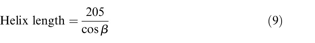
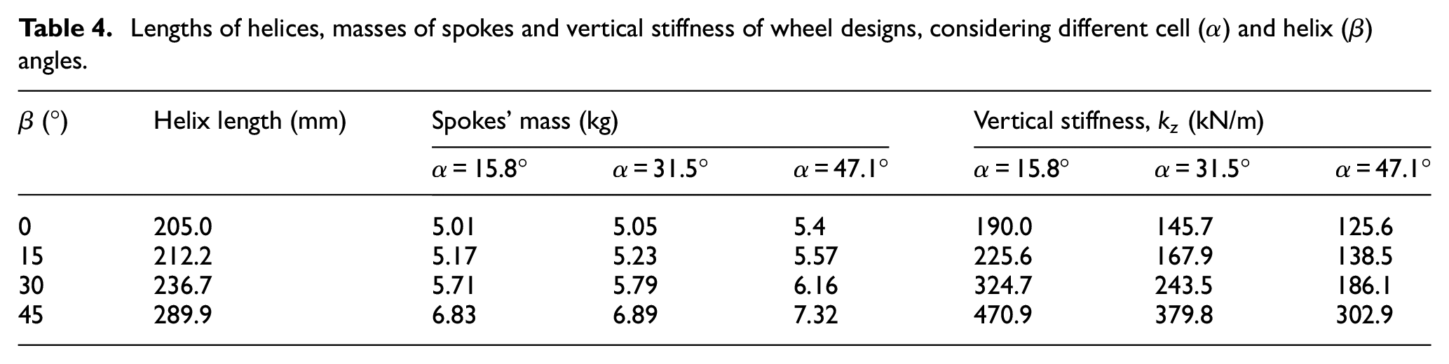
The honeycomb wheel with 12 different spokes configurations of varying cell (=15.8°, 31.5° and 47.1°) and helix (=0°, 15°, 30° and 45°) angles were initially assigned with constant cell-wall thickness (=3.5 mm), as stated above. The vertical, longitudinal, lateral and yaw stiffness of the honeycomb wheel models were evaluated using the methods described in Section 2.1. The vertical stiffness () of these wheel designs under a constant normal load (3 kN) are summarized in Table 4 together with the mass of each spoke configuration and the length of its associated helix (Figure 3), which relates to and the width of the rim (205 mm) as:
Lengths of helices, masses of spokes and vertical stiffness of wheel designs, considering different cell () and helix () angles.
(°)
Helix length (mm)
Spokes’ mass (kg)
Vertical stiffness, (kN/m)
= 15.8°
= 31.5°
= 47.1°
= 15.8°
= 31.5°
= 47.1°
0
205.0
5.01
5.05
5.4
190.0
145.7
125.6
15
212.2
5.17
5.23
5.57
225.6
167.9
138.5
30
236.7
5.71
5.79
6.16
324.7
243.5
186.1
45
289.9
6.83
6.89
7.32
470.9
379.8
302.9
As it would be expected, increasing the helix angle yields notable increases in the length of the helix (equation (9)), total mass of the spokes and of the wheel, irrespective of the value considered. More evident increases are observed corresponding to higher , particularly when it is increased from 30° to 45°. Moreover, the relative increases in are considerably higher, when compared to those corresponding to masses of the spokes and thus the wheel. For instance, increasing from 0° to 45° results in 147.1% increase in of the wheel model with =15.8°, while the corresponding increases in the spokes mass is 36.3%. It should be noted that the mass of the other components of the honeycomb wheel is about 10 kg.
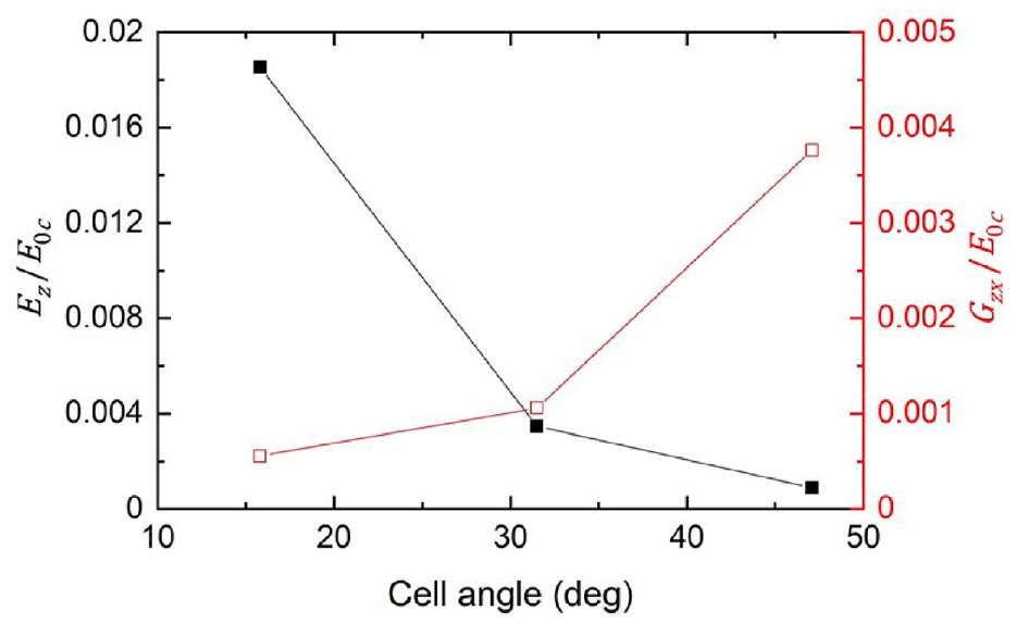
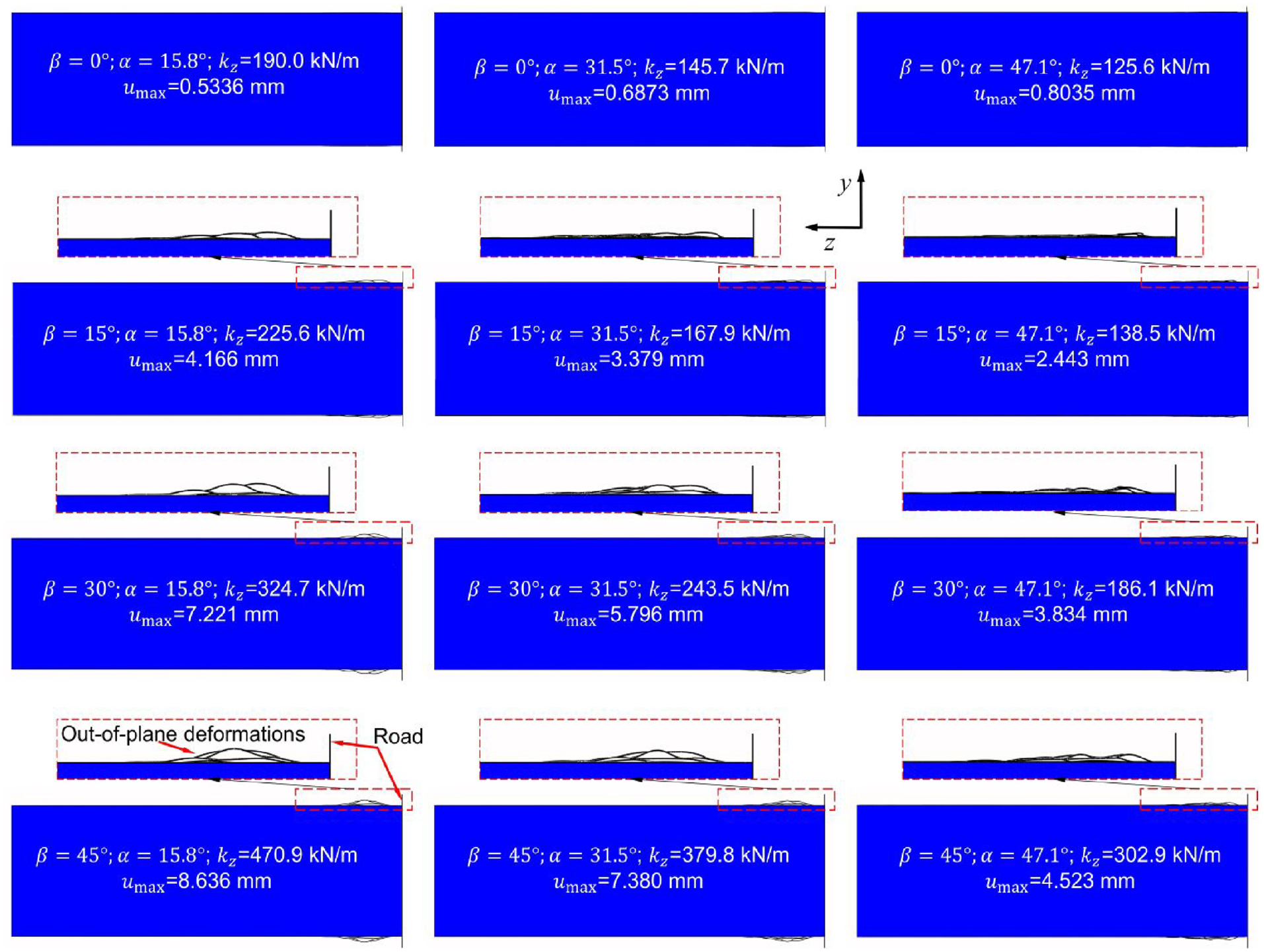
An increase in cell angle from 15.8° to 31.5°, on the other hand, results in 23.5% reduction in of the wheel model with =0°, as seen in Table 4. A further increase to 47.1°, however, leads to relatively smaller reduction in (13.8%). This negative and nonlinear effect of on is consistent with its influence on the radial effective elastic modulus (), as seen in equation (7), of the 2D spoke normalized to the initial elastic modulus of its constituent material (), which significantly affects of the wheel, as depicted in Figure 5. Figure also shows variations in the normalized shear modulus () as a function of . Both the normalized radial elastic () as well as shear () moduli were calculated using equations (5) and (7), considering =3.5 mm and mean dimensions (, e and d) of the 2D spoke presented in Table 1. Similar variations in with varying are also observed for the wheel with spokes configurations of =15°, 30° and 45°. This is attributable to the fact that the normal load acting on the rim center is suspended to the shear ring by the spokes away from the vicinity of wheel/road contact region,7 which invariably show negligible out-of-plane deformations for all values considered, as depicted in Figure 6. The peak deformation () of the spokes along the y-direction of the wheel is also presented in this figure. Moreover, increasing from 15.8° to 31.5° yields only slightly higher mass of the spokes, irrespective of value considered, while a relatively higher increase (≈6.5%) in the mass is observed when is increased to 47.1°. This is consistent with the influence of on the summation of cell-wall lengths and heights of a sector or partial 2D honeycomb spoke (Figure 1(a)), considering identical for each spokes configuration and the constant wheel width, as partly seen in Table 1.
Influences of the cell angle on the normalized radial () and shear () effective moduli of the 2D honeycomb spoke with = 0°.
Deformations of the honeycomb NPW with spokes configurations of varying helix () and cell () angles (normal load = 3 kN).
Parametric studies of the wheel designs with =0°, reported in,21 suggested that increasing the initial elastic moduli or thicknesses of the tread, core layer and the honeycomb cell-wall, from 40% to 200%, yielded less than 40% increase in of the wheel. It can thus be concluded that is a more dominant design parameter concerning , when compared to the design parameters considered in Zheng et al.,21 including . This is of particular importance for designing wheels with high load-carrying capacity for applications in heavy-duty vehicles. It should also be mentioned that increasing causes relatively small increase (≤12.5%) in mass of the wheel and may thus exhibit only slightly higher rolling resistance. Therefore, the NPW designs with symmetric helical spokes may be considered as improved substitutes of the pneumatic tires in heavy goods vehicles.
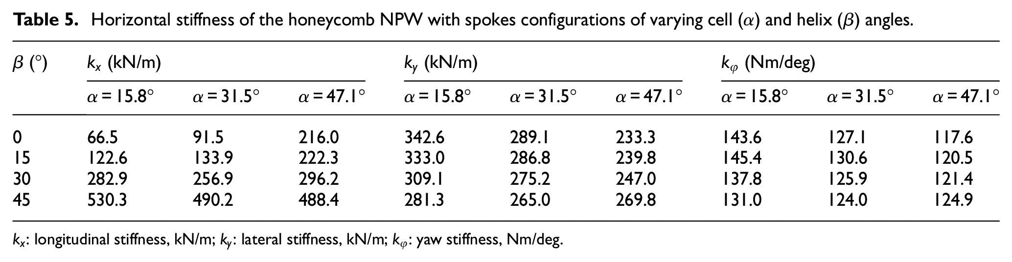
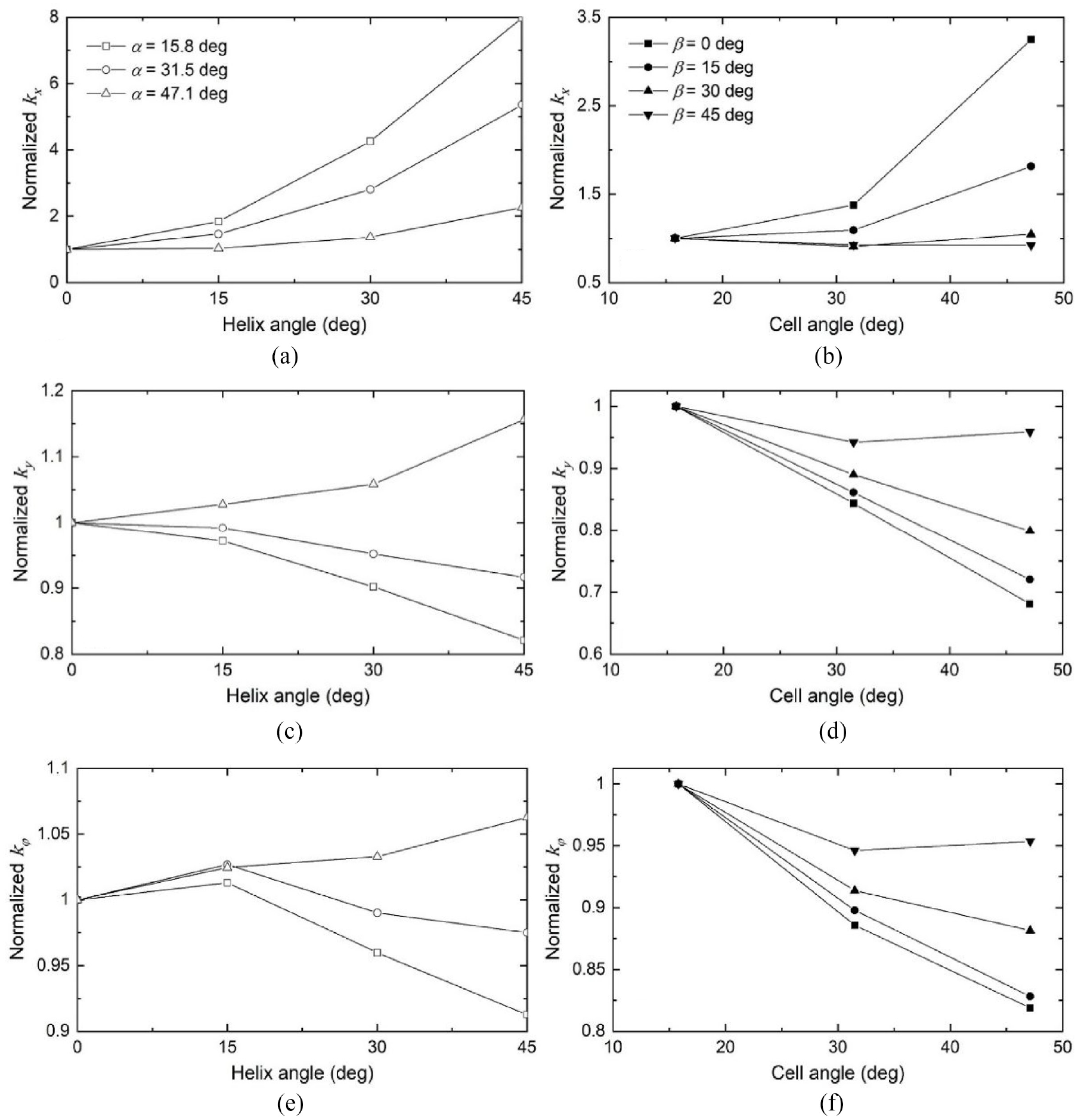
The horizontal stiffness values of the honeycomb wheel in terms of longitudinal, lateral and yaw stiffness are summarized in Table 5, considering 12 spokes configurations of different and together with 3 kN normal load. The simulation results for each of the three stiffness properties were subsequently normalized with respect to those of the wheel design with spokes configurations of =0° or =15.8° so as to clearly reveal their dependence on helix or cell angles, as illustrated in Figure 7.
Horizontal stiffness of the honeycomb NPW with spokes configurations of varying cell () and helix () angles.
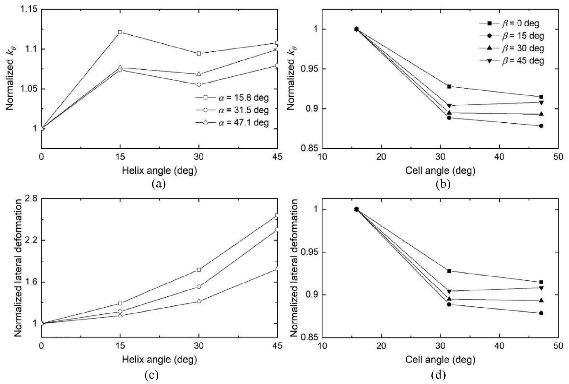
Influences of helix and cell angles, and , on the normalized wheel stiffness: (a and b) longitudinal, ; (c and d) lateral, ; (e and f) yaw, .
The wheel designs with 15.8° and 31.5° cell angles show too low under 3 kN normal load, in the 66.5–91.5 kN/m range, when =0°, as seen in Table 5. These stiffness values are much smaller than those of most passenger car pneumatic tires, which generally exceed 200 kN/m.21,37 Too low may cause large wheel deformations and stresses under relatively high longitudinal slip conditions, resulting in potentially undesired sensation of discomfort under driving/braking maneuvers as well as reduced service life of the NPW. Increasing , however, could help achieve notable increase in , which is particularly evident when for lower , as shown in Figure 7(a). This is partly attributable to the higher helix length, and in-part to the fact that the spokes of the loaded honeycomb wheel show higher increases in their out-of-plane deformations near the wheel/road contact region at lower , which may generate more resistances to subsequent in-plane shear deformations, as depicted in Figure 6. Increasing could also yield higher for the wheel models with =0°, as seen in Figure 7(b). Moreover, more considerable increase is observed when is increased from 31.5° to 47.1°. This nonlinear and positive trend is consistent with the influence of on the normalized (in-plane) shear elastic modulus () of the 2D spoke, which significantly affects of the wheel, as seen in Figure 5. Furthermore, the cell angle also shows positive influence on when is increased to 15°, although with less increase as compared to the case of =0°. A further increase in to 30° and 45° causes only slight variations in of the wheel, when increasing . These indicate that becomes insignificant with respect to when high out-of-plane deformations occur in the spokes. In addition, the spokes configurations with =15° and 30° or =47.1° and 30° could be considered as proper designs with regards to of the wheel. It should be noted that could also be tuned by varying initial elastic moduli and thicknesses of the honeycomb cell-wall and the core layer,21 although their corresponding influences are generally smaller than those of and .
Lower is obtained with an increase in for the wheel models with =15.8°, as depicted in Figure 7(c). This is due to the fact the spokes of higher exhibit more out-of-plane deformations under 3 kN normal load (Figure 6), and therefore are considered less resistant to additional lateral deformations resulting from shear loads in the y-direction. As expected, relatively less decrease in was observed when increasing to 31.5°, owing to the decreasing out-of-plane deformations in the spokes (Figure 6). This negative influence of , however, switches to positive with a further increase, within the cell angles range considered. This is likely due to the different deformation patterns observed in wheel spokes of different , when subjected to shear loading along the y-axis. For example, Figure 8 depicts the deformations of the wheel spokes with =0° and =15.8°, 31.5° and 47.1°, respectively, considering 3 kN normal load and 5 mm lateral displacement. In this figure, the spokes with =15.8° and 31.5° reveal bending deformations near the contact region, while those with =47.1° show both bending and out-of-plane shear deformations, which could be attributed to their relatively higher mean cell-length (Table 1).
Deformation patterns of the spokes corresponding to loaded NPW models with 0° helix angle and: (a) cell angle = 15.8°, (b) cell angle = 31.5° and (c) cell angle = 47.1° (normal load = 3 kN, lateral displacement = 5 mm).
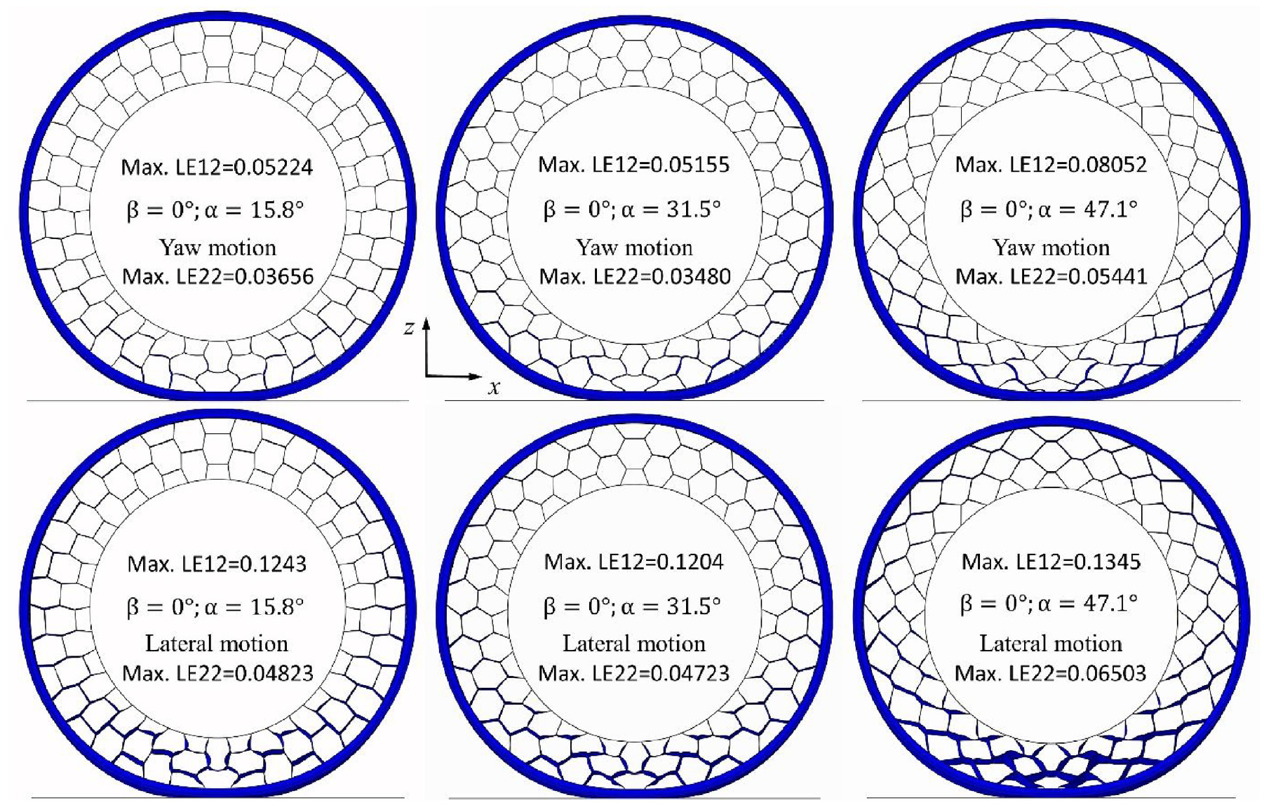
Similar but smaller influences of were observed with regards to the yaw stiffness , when compared to those on of the wheel, as illustrated in Figure 7(c) and (e). This indicates that the yaw moment responses of the wheel models with different spokes configurations are primarily determined by their lateral stiffness properties. Moreover, the comparatively smaller influences (≤9%) of on are attributed to relatively smaller contributions of cellular spokes to yaw deformation of the honeycomb wheel as compared to its lateral deformation. This is evidenced from the out-of-plane deformations of the wheel models under yaw and lateral motions, presented in Figure 9, considering =0° and =15.8°, 31.5° and 47.1°, respectively. This could also be quantitatively evidenced by the peak logarithmic normal (LE22) and shear (LE12) strains associated with the nodes of the spokes (shell) elements, as illustrated in Figure 9. “1” denotes the direction perpendicular to “2,” which coincides with the y-direction of the wheel. Both “1” and “2” directions lie in the plane of the shell element.29 It should be noted that the both the yaw moments and lateral forces of these wheel models approach the road friction limit. In addition, increasing from 0° to 15° causes slightly higher for the wheel models with =15.8° and 31.5°. This is likely due to the positive influence of on (Figure 7(a)), although its contributions to yaw stiffness property is relatively small.
Out-of-plane deformations of the spokes corresponding to loaded NPW models under yaw and lateral motions, considering 0° helix angle and 15.8°, 31.5° and 47.1° cell angles (normal load = 3 kN, yaw rotation angle = 5°, lateral displacement = 10 mm).
Increasing from 15.8° to 47.1° causes 32% and 18% reductions in and of the wheel models with =0°, respectively, as illustrated in Figure 7(d) and (f). These reductions are attributable to the decreasing (negative) effect of on out-of-plane stiffness properties of the wheel spokes.21 Moreover, the comparatively smaller influence of on is owing to the relatively smaller contributions of cellular spokes to yaw deformations of the honeycomb wheel as compared to its lateral deformations. Furthermore, these negative influences tend to diminish for the design with higher and tend to saturate when is increased to 45°. These suggest that becomes less important in view of and , when the honeycomb spokes undergo higher out-of-plane deformations, as seen in Figure 6. This saturation tendency is consistent with its influence on , as illustrated in Figure 7(b).
Cornering stiffness characteristics
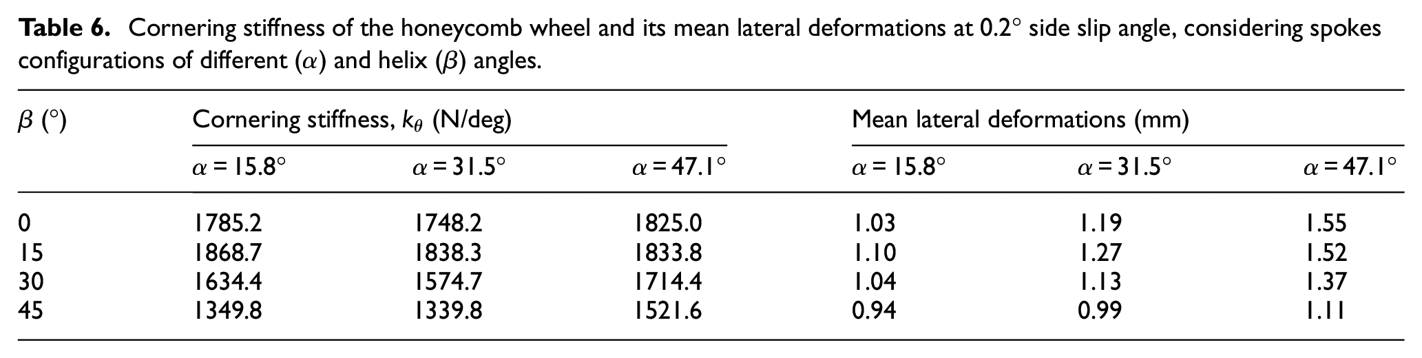
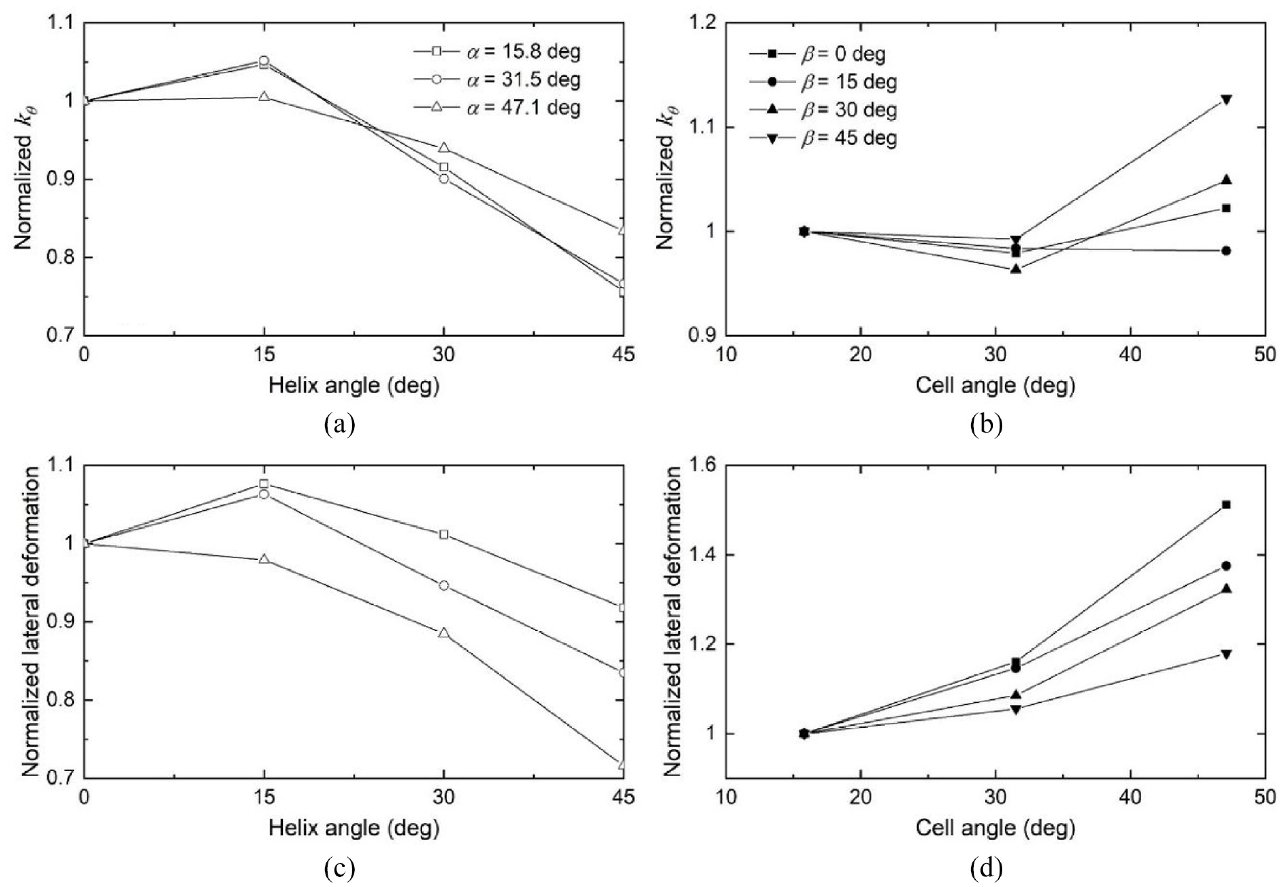
Table 6 summarizes cornering stiffness () of the honeycomb wheel models with 12 different spokes configurations, considering 3 kN normal load and 10 km/h forward velocity, together with their mean lateral deformations at 0.2° side slip angle (). It should be mentioned that was evaluated within relatively small side slip angle range (0–0.2°), as stated above. Moreover, a lower speed was selected for simulations since the effect of speed on the cornering stiffness is known to be small, as stated in Section 2.2. This permitted simulations in a more computationally effective manner. In order to clearly show the influences of cell and helix angles on , the stiffness results in this table were subsequently normalized to those of the wheel models with =0° or =15.8°, as shown in Figure 10(a) and (b).
Cornering stiffness of the honeycomb wheel and its mean lateral deformations at 0.2° side slip angle, considering spokes configurations of different () and helix () angles.
(°)
Cornering stiffness, (N/deg)
Mean lateral deformations (mm)
= 15.8°
= 31.5°
= 47.1°
= 15.8°
= 31.5°
= 47.1°
0
1785.2
1748.2
1825.0
1.03
1.19
1.55
15
1868.7
1838.3
1833.8
1.10
1.27
1.52
30
1634.4
1574.7
1714.4
1.04
1.13
1.37
45
1349.8
1339.8
1521.6
0.94
0.99
1.11
Influences of helix and cell angles, and , on normalized: (a and b) cornering stiffness, ; (c and d) mean lateral deformation.
It should be noted that of a rolling wheel is related to its mean lateral deformation within the contact area as well as , which is obtained under stationary conditions (Table 5). This is due to the fact that the cornering force at a sufficiently small side slip angle, where the rubber tread sticks to the ground with minimal slippage, could be approximately estimated as the product of its mean lateral deformation and .38 For instance, the cornering force estimated for the wheel model with =15.8° and =0° is 351.3 N at 0.2° side slip angle, which is slightly smaller but in reasonable close agreement with the simulation result, in the order of 357.1 N. Therefore, Figure 10(c) and 10(d) present the influences of and on mean lateral deformation of the rolling wheel (Table 6) normalized with respect to those with =0° or =15.8° so as to reach a better understanding of their effects on .
Opposing influences of are observed with regards to and mean lateral deformation of the wheel, when is increased from 0° to 15°, for each value considered, as seen in Figures 7(c) and 10(c). For instance, the wheel model with =15.8° revealed 7.6% increase in its mean lateral deformation but only 2.8% decrease in . This causes only slight increases in of the wheel models with different , ranging from 0.5% to 5%, as shown in Figure 10(a). A further increase in from 15° to 45° causes notably lower mean lateral deformation and for the wheel models with =15.8° and 31.5°. The wheel model with =47.1°, however, keeps showing opposite variations in these two performance measures. These lead to relatively smaller influences of on of the wheel model with =47.1°, when compared to those with 15.8° and 31.5° cell angles, as observed in Figure 10(a). It should be stressed that increasing from 0° to 45° could yield 24%, 23% and 17% reductions in of the wheel models with =15.8°, 31.5° and 47.1°, respectively.
An increase in invariably causes higher mean lateral deformation for the wheel models with varying , as seen in Figure 10(d). This positive influence diminishes with increasing helix angle. Opposite trends, however, are observed in the influences of on of the wheel, as shown in Figure 7(d). Therefore, varying in general results in only slight variations in , as depicted in Figure 10(b), although the wheel model with =45° exhibits about 13% increase in its cornering stiffness.
It is clearly seen that in the absence of , the wheel designs show very high cornering stiffness, , in the range of 1748.2–1825.0 N/deg (Table 6), when compared to that of the reference pneumatic tire (≈830 N/deg). This could lead to inferior direction control of the vehicle, particularly under high operating speeds and relatively large side slip angles. Moreover, these designs need to be coupled with higher in order to achieve proper (Table 5 and Figure 7), resulting in reduced design space. Introducing “symmetric helical honeycomb spokes” could thus effectively lower cornering stiffness, ranging from 1339.8 to 1521.6 N/deg, as well as substantially higher longitudinal stiffness, , which could be easily tuned comparable to those of the pneumatic tires. It should be mentioned that cornering stiffness could be further reduced by tuning the cell-wall thickness and the design parameters related to the core layer and the tread.26
The abovementioned static and dynamic simulations were repeated for the 12 honeycomb wheel models with identical load carrying capacity, which was achieved by tuning their corresponding cell-wall thickness () in order to yield same vertical deflection under the 3 kN normal load. It should be mentioned that 15.80 mm vertical deflection was initially chosen, which could yield 190 kN/m vertical stiffness () as that of the above-stated reference pneumatic tire.30 This vertical deflection, however, caused convergence difficulties for the wheel model with =15.8° and =45° in static loading simulations, resulting from its much higher out-of-plane deformations in the honeycomb spokes near the wheel/road contact area. This could be evidenced from the out-of-plane deformations presented in Figure 6, although the wheel model with =15.8° and =45° shows highest and least vertical deflection. Therefore, a relatively smaller vertical deflection, in the order of 11.54 mm, was chosen which could ensure converged solutions for each wheel model and thus the study of wheel stiffness properties over a broad helix angle range. It should be noted that the chosen vertical deflection and the 3 kN normal load resulted in =260 kN/m for each wheel model.
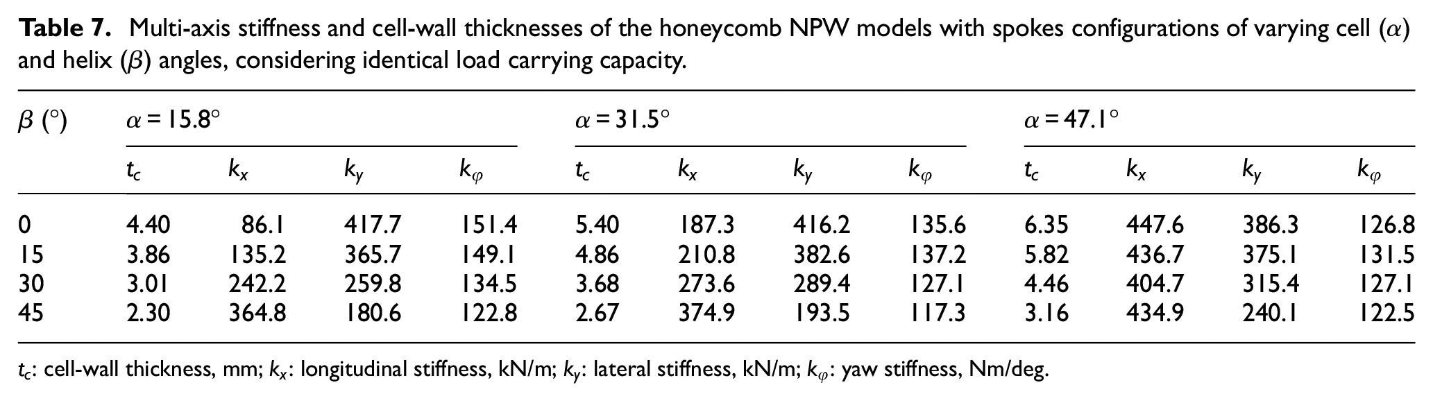
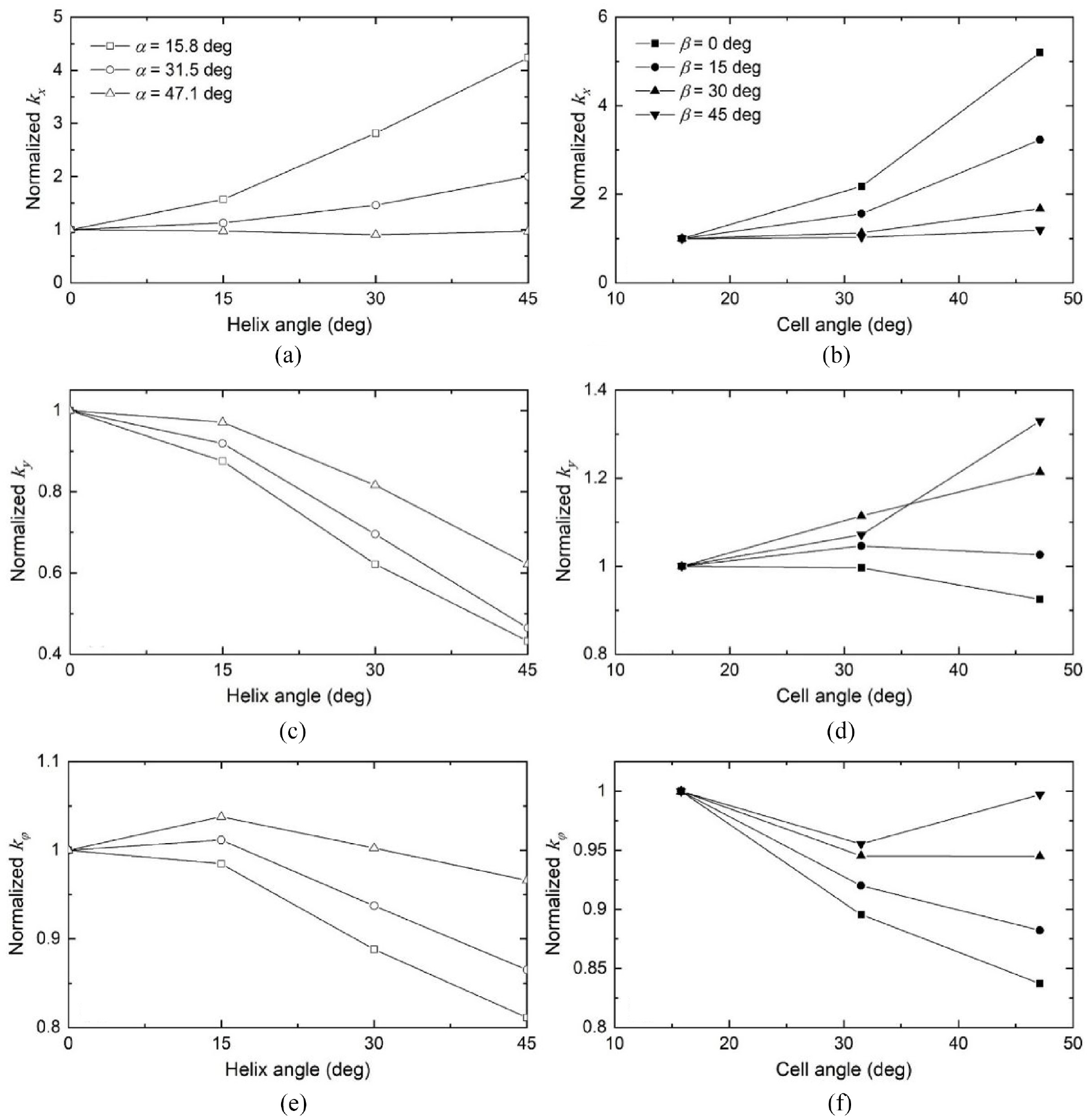
Table 7 summarizes the longitudinal (), lateral () and yaw () stiffness of the honeycomb NPW models with different spokes configurations, together with their corresponding . In this table, the wheel model with higher or lower invariably necessitated smaller so as to yield the chosen load carrying capacity or vertical stiffness (260 kN/m). These indicate positive and negative influences of and on of the wheel, respectively, which are consistent with those observed in Table 4. The longitudinal, lateral and yaw stiffness results were subsequently normalized with respect to those of the wheel models with =0° or =15.8°, which are presented in Figure 11.
Multi-axis stiffness and cell-wall thicknesses of the honeycomb NPW models with spokes configurations of varying cell () and helix () angles, considering identical load carrying capacity.
Variations in normalized stiffness with varying helix and cell angles ( and ) considering same load carrying capacity: (a and b) longitudinal, ; (c and d) lateral, ; (e and f) yaw .
Considerably smaller variations in , in the range of −10% to 324%, were observed with varying when compared to those (0-698%) corresponding to the honeycomb NPW designs with same =3.5 mm, for the values range considered, as seen in Figures 7(a) and 11(a). This is attributable to lower value of (Table 7) associated with the wheel models with higher in order to achieve identical load carrying capacity, which causes lower normalized shear effective modulus (, equation (5)) of the honeycomb spokes and thus reductions in of the wheel. Similarly, increasing results in more evident variations in (Figure 11(b)), when compared to the results presented in Figure 7(b). This is owing to the increase in for the wheel models with spokes configurations of higher (Table 7), which results in additional increase in .
Lower with 54-57% reductions were obtained for the wheel models with =15.8° and 31.5°, when increasing from 0° to 45°, as seen in Figure 11(c). These substantial decreases are partly due to the negative influences of on (Figure 7(c)), and in-part to the lower of the wheel models with higher helix angle (Table 7). Unlike the positive influences of on observed in the wheel designs with =47.1° and =3.5 mm (Figure 7(c)), lower lateral stiffness with 3-38% decreases could be achieved by tuning the helix angle, as depicted in Figure 11(c). The cell-wall thickness could thus be viewed as a more dominating parameter on as compared to the helix angle, within and values range considered. Moreover, up to 32% reductions in were obtained with an increase in of the wheel models with three different (Figure 7(d)). These reductions, however, are coupled with the increases in resulting from the higher associated with the wheel models with higher (Table 7), irrespective of value considered. Therefore, the negative effects of on of the wheel, shown in Figure 7(d), tend to diminish and switch to positive effects with an increase in , as depicted in Figure 11(d).
Similar influences of the decreasing (Table 7) were also observed on variations in corresponding to the wheel models with varying (Figures 7(e) and 11(e)), when comparing its effects on , shown in Figures 7(c) and 11(c). The influences of on , however, are much smaller than those observed on . For example, a decrease in causes about 10% additional reduction in for the wheel model with =15.8° and =45° (Figures 7(e) and 11(e)), while corresponding reduction in its is around 39%, as seen in Figures 7(c) and 11(c). This is owing to the relatively smaller contributions of cellular spokes to yaw deformations of the honeycomb wheel as compared to its lateral deformations, as mentioned above. Therefore, only limited differences were observed in variations in with varying , when comparing the results presented in Figures 7(f) and 11(f).
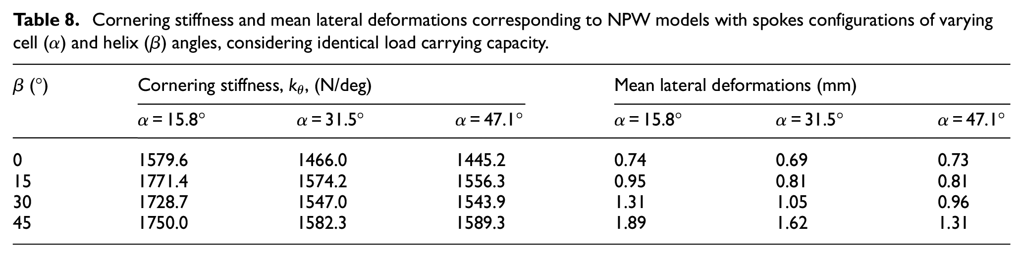
Table 8 summarized cornering stiffness, , of the 12 wheel models with different and , apart from their mean lateral deformations at 0.2° side slip angle (). The results were also normalized with respect to those corresponding to the wheel models with =0° or =15.8°, as shown in Figure 12(a) and (b).
Cornering stiffness and mean lateral deformations corresponding to NPW models with spokes configurations of varying cell () and helix () angles, considering identical load carrying capacity.
(°)
Cornering stiffness, , (N/deg)
Mean lateral deformations (mm)
= 15.8°
= 31.5°
= 47.1°
= 15.8°
= 31.5°
= 47.1°
0
1579.6
1466.0
1445.2
0.74
0.69
0.73
15
1771.4
1574.2
1556.3
0.95
0.81
0.81
30
1728.7
1547.0
1543.9
1.31
1.05
0.96
45
1750.0
1582.3
1589.3
1.89
1.62
1.31
Influences of helix and cell angles, and , on normalized: (a and b) cornering stiffness, ; (c and d) mean lateral deformation.
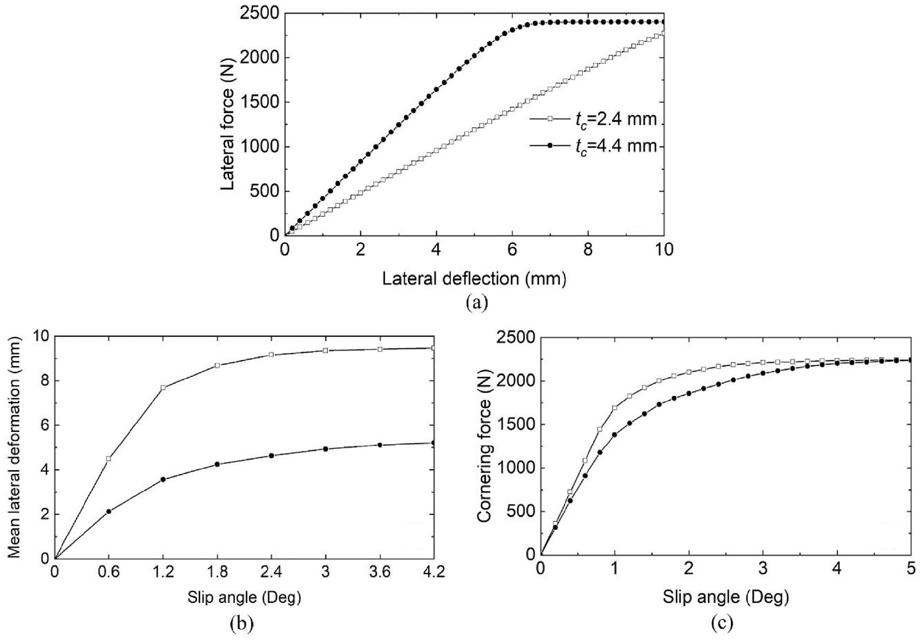
The results presented in Figure 12(a) and (b) suggest positive and negative effects of and , respectively, on of the wheel models designed with identical loading carrying capacity. The observed effects are nearly opposite to those seen for the designs with identical cell-wall thickness (Figure 10(a) and (b)). These suggest that a decrease in results in higher , which could be evidenced by its influence on and mean lateral deformation of the wheel. In order to gain a better understanding of the cornering behavior, additional simulations were performed so as to obtain variations in lateral force, mean lateral deformation and cornering force corresponding to the wheel with different . For instance, Figure 13 depicts lateral force-deflection characteristics of the stationary wheel, and mean lateral deformation and cornering force responses of the rolling wheel as a function of side slip angle, for two different (2.40 and 4.40 mm). The results were obtained for the wheel model with spokes configuration of =15.8° and absence of helix (=0°). It should be mentioned that the multi-axis and cornering stiffness values of the wheel model with =15.8°, =0° and =4.40 mm were summarized Tables 7 and 8. As it would be expected, an increase in leads to about 71% higher , from 243.5 kN/m to 416.3 kN/m, together with 48.7% lower mean lateral deformation corresponding to 0.6° side slip angle. Therefore, increasing from 2.4 mm to 4.4 mm causes about 12.2% reduction in . The negative effects of on could also be reflected by comparing the results presented in Figures 7(c) and 11(c) as well as those in Figures 10(c) and 12(c).
Comparisons of: (a) lateral force-deflection, (b) mean lateral deformation and (c) cornering force-side slip angle relations of the NPW model with varying cell-wall thickness ().
Conclusions
NPWs with non-helical honeycomb spokes configurations may cause inferior handling characteristics of the vehicle owing to their too high cornering stiffness. A novel design concept involving symmetric helical honeycomb spokes is thus proposed to lower cornering stiffness of the NPW. The stiffness properties of the honeycomb NPW are investigated together with their dependence on the helix angle and cell angle, using FE methods. The main findings are listed as follows:
3D FE models developed for NPW with honeycomb spokes configurations of 0° helix angle and varying cell angles revealed relatively close agreements with reported results. These included peak local stresses in the cellular spokes of the stationary wheel and its overall vertical deflections, apart from its cornering stiffness obtained under rolling conditions, considering 2–4 kN normal load and 10 km/h forward velocity.
The NPW designs with spokes configurations of low cell angles and 0° helix angle showed considerably smaller longitudinal stiffness, when compared to their pneumatic counterparts. This was attributed to the relatively high in-plane shear flexibility associated with the spokes. On the other hand, their high out-of-plane stiffness caused significantly higher lateral and cornering stiffness for the NPW as compared to those of the pneumatic tires of similar dimensions. An increase in the cell angle could help yield longitudinal stiffness similar to the pneumatic tires together with the lower lateral stiffness. This, however, resulted in notable reduction in vertical stiffness of the NPW, apart from limited variation in its cornering stiffness.
Increasing the helix angle could yield greater in-plane stiffness of the cellular spokes and thus higher longitudinal and vertical stiffness of the NPW, apart from lower lateral and yaw stiffness, particularly for the lower cell angle considered. The increased longitudinal stiffness is expected to offer better ride quality under high longitudinal slip conditions. This could also lead to notably lower cornering stiffness, particularly when the helix angle is higher than 15°, resulting in improved handling performance of the vehicle. The cell-wall thickness also showed negative effects on wheel cornering stiffness.
The NPWs with symmetric helical spokes of 45° helix angle could be used in heavy duty vehicles owing to their extremely high load carrying ability with relatively low mass.
The novel design concept could be considered as improved design in view of vehicle braking/traction, handling and ride performances, particularly for high-speed passenger cars.
Footnotes
Appendix
Acknowledgements
Support from Ministère de l’Économie et de l’Innovation (MEI), ALIGO innovation (Axelys), Shanshan Chen and Ran Guo is gratefully acknowledged.
Declaration of conflicting interests
The author(s) declared no potential conflicts of interest with respect to the research, authorship, and/or publication of this article.
Funding
The author(s) received no financial support for the research, authorship, and/or publication of this article.
ORCID iD
Zhou Zheng
References
1.
ShokouhfarSRakhejaSGindyME. Development of a rolling truck tyre model using an automatic model regeneration algorithm. Int J Veh Syst Model Test2016; 11(1): 68–95.
2.
ZhengZRakhejaSSedaghatiR. Modal properties of honeycomb wheels: A parametric analysis using response surface method. Eur J Mech Solids2023; 97: 1–16.
3.
FuHLiangXChenK, et al. Study on key mechanical properties of the flexible spoke non-pneumatic tire considering thermo-mechanical coupling. Adv Eng Softw2022; 173: 1–12.
4.
JuJKimDMKimK. Flexible cellular solid spokes of a non-pneumatic tire. Compos Struct2012; 94(8): 2285–2295.
5.
RhyneTBCronSM. Development of a non-pneumatic wheel. Tire Sci Technol2006; 34(3): 150–169.
6.
ZhaoYQZangLGChenYQ, et al. Non-pneumatic mechanical elastic wheel natural dynamic characteristics and influencing factors. J Cent South Univ2015; 22(5): 1707–1715.
7.
ZhengZRakhejaSSedaghatiR. A comparative study of static and dynamic properties of honeycomb non-pneumatic wheels and a pneumatic wheel. Proc IMechE Part D: J Automobile Engineering2021; 235(14): 3631–3646.
8.
YooSUddinMSHeoH, et al. Thermoviscoelastic modeling of a nonpneumatic tire with a lattice spoke. Proc IMechE Part D: J Automobile Engineering2017; 231(2): 241–252.
9.
AliMMaarijMHussainA. Design and structural analysis of non-pneumatic tyres for different structures of polyurethane spokes. J Eng Appl Sci2022; 69: 1–21.
10.
ZangLWangXYanP, et al. Structural design and characteristics of a non-pneumatic tire with honeycomb structure. Mech Adv Mater Struct2022; 29(25): 4066–4073.
11.
Aboul-YazidAMEmamMAAShaabanS, et al. Effect of spokes structures on characteristics performance of non-pneumatic tires. Int J Automot Eng2015; 11: 2212–2223.
12.
RugsajRSuvanjumratC. Study of geometric effects on nonpneumatic tire spoke structures using finite element method. Mech Based Des Struc2022; 50(7): 2379–2399.
13.
ZhangZFuHLiangX, et al. Comparative analysis of static and dynamic performance of nonpneumatic tire with flexible spoke structure. Stroj Vestn-J Mech E2020; 66(7-8): 458–466.
14.
LeeCJuJKimD. Vibration analysis of non-pneumatic tires with hexagonal lattice spokes. In: ASME international design engineering technical conferences & computers & information in engineering conference, Chicago, Illinois, USA, 12-15Aug2012, paper no. DETC2012-70538, pp.483–490. New York: ASME.
15.
LeeCJuJKimD. The dynamic properties of a non-pneumatic tire with flexible auxetic honeycomb spokes. In: ASME international mechanical engineering congress & exposition, Houston, Texas, USA, 9-15Nov2012, paper no. IMECE2012-88199, pp.605–615. New York: ASME.
16.
BurkeAMOlatunbosunOA. New techniques in tyre modal analysis usingMSC/NASTRAN. Int J Veh Des1997; 18(2): 203–212.
17.
ShokouhfarSRakhejaSGindyME. Modal analysis of a rolling truck tyre subjected to inflation pressure and vertical deflection. Int J Veh Syst Model Test2016; 11(2): 116–141.
18.
HeHXingYWangR, et al. Optimization design of cooling system for injection molding mold of non-pneumatic tire. Therm Sci Eng Prog2023; 42: 1–10.
19.
SardinhaMReisLRamosT, et al. Non-pneumatic tire designs suitable for fused filament fabrication: an overview. Procedia Struct Integr2022; 42: 1098–1105.
20.
AndriyaNDuttaVVaniVV. Study on 3D printed auxetic structure-based non-pneumatic tyres (NPT’S). Mater Manuf Process2022; 37(11): 1280–1297.
21.
ZhengZRakhejaSSedaghatiR. Multi-axis stiffness and road contact characteristics of honeycomb wheels: A parametric analysis using Taguchi method. Compos Struct2022; 279: 114735.
22.
JinXHouCFanX, et al. Investigation on the static and dynamic behaviors of non-pneumatic tires with honeycomb spokes. Compos Struct2018; 187: 27–35.
23.
KimKKimD. Contact pressure of non-pneumatic tires with hexagonal lattice spokes. SAE Technical Paper 2011-01-0099, 2011.
24.
KimKKimSJuJ, et al. Contact pressure of a non-pneumatic tire with three-dimensional cellular spokes. In: ASME mechanical engineering congress & exposition, Denver, Colorado, USA, 11-17 Nov 2011, paper no. IMECE2011-64233, pp.283–293. New York: ASME.
25.
Ganniari-PapageorgiouEChatzistergosPWangX. The influence of the honeycomb design parameters on the mechanical behavior of Non-Pneumatic tires. Int J Appl Mech2020; 12(03): 2050024.
26.
ZhengZRakhejaSSedaghatiR. Cornering stiffness characteristics of honeycomb wheels: A parametric analysis using response surface method. Compos Struct2022; 288: 115418.
27.
JuJVeeramurthyMSummersJD, et al. Rolling resistance of a nonpneumatic tire having a porous elastomer composite shear band. Tire Sci Technol2013; 41(3): 154–173.
28.
GibsonLJAshbyMFSchajerG, et al. The mechanics of two-dimensional cellular materials. Proc Roy Soc Lond A1982; 382: 25–42.
LiangCWangGZhengZ. An effect study of passenger car radial tire contour design theory on tire force and moment properties. SAE Technical Paper 2016-01-0446, 2016.
31.
OlatunbosunOABolarinwaO. FE simulation of the effect of tire design parameters on lateral forces and moments. Tire Sci Technol2004; 32(3): 146–163.
32.
GeHQuezadaJCHouerouVL, et al. Multiscale analysis of tire and asphalt pavement interaction via coupling FEM–DEM simulation. Eng Struct2022; 256: 1–13.
33.
RaoKKumarR. Simulation of tire dynamic behavior using various finite element techniques. Int J Comput Methods Eng Sci Mech2007; 8: 363–372.
34.
WeiCOlatunbosunOA. Transient dynamic behaviour of finite element tire traversing obstacles with different heights. J Terramechanics2014; 56: 1–16.
35.
ChoJRKimKWJeonDH, et al. Transient dynamic response analysis of 3-D patterned tire rolling over cleat. Eur J Mech A-Solid2005; 24(3): 519–531.
36.
WeiCOlatunbosunOA. The effects of tyre material and structure properties on relaxation length using finite element method. Mater Des2016; 102: 14–20.