
Abstract
There is an ever-increasing stringent directive for environmental protection, even for the previously rather negligible lubricant leakage from vehicular drivetrains. Leakage from transmissions and differential units are no longer permitted and can lead to excessive warranty costs. Additionally, the trend in component downsizing, including for sealing systems has indirectly altered the leakage behaviour of transmissions. To guarantee leakage-free operation, it is important to establish standardised methods of manufacturing processes, particularly for surface topography of shafts. The paper investigates the leakage from two different shaft machining processes: corundum and cubic boron nitride (CBN) grinding. The performance of passenger car transmission sealing system is ascertained with the development and use of a novel detailed representative fully instrumented test rig. A test protocol is set up to assess the performance of shafts during break-in period and correlate shaft topographic data with its measured performance. The results show that the measured oil leakage correlates well with the shaft surface skewness whilst no particular trend is observed with Ra, Rz and shaft lead angle values, which form the basis of most current standards used in industry. Overall, it was observed that shafts with negative skewness in their roughness profile produced lesser leakage. A basic analytical predictive method is also developed which corroborates with the measured data.
Introduction
In vehicular differentials and transmissions, as in many other applications, leaking seals can lead to environmental pollution, also resulting in excessive warranty claims.1,2 The performance of a sealing system, comprising a gearbox, rotary shaft seals and a driveshaft is significantly influenced by several internal and external factors during various vehicle manoeuvres. 3 These influential factors/conditions are shown in Figure 1. Among them surface quality of the seal, 4 design of the radial shaft seal and the operating behaviour of the transmission fluid are the most prominent.
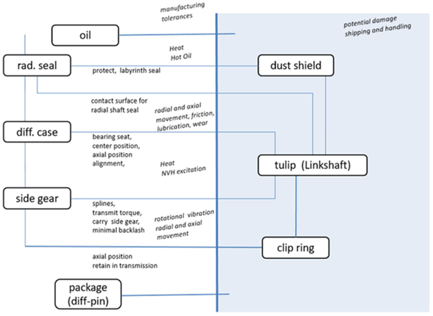
Influential factors in a vehicular transmission sealing system.
Much attention has been paid to the surface topography and texture of mating surfaces of radial lip seals. 5 Some specific studies, linking surface topography to leakage, operational reliability and pumping have included the effect of wear tracks, 6 shaft surface roughness 7 as well as non-Ra roughness parameters, 8 which have been shown to exhibit better correlation with the seal leakage performance.
A more systemic approach was proposed by Buhl 9 who used a model, considering all the components of a sealing system, including the radial shaft seals, in which the shaft surface and the containing fluid were affected by the mechanism of pumping. Buhl’s investigation distinguished between active and passive lubricant flows within a sealing system. The direct active flow is affected by the shaft and lip seal surface topographies, whilst the indirect conveyance of the fluid is considered to be as the result of formation of any counter face conveyable structures to the sealing lip. Nevertheless, from a practical point of view, it is immaterial whether any counter face itself provides a directed fluid flow. However, according to Baumann 10 the lead structures on the shaft counter face are usually responsible for early failures of radial lip seals or can result in an increasing lubricant leakage rate. Baumann 10 described an axial pumping effect caused by the rotation of the shaft in the sealing ring. In such a case, the liquid flow is conveyed either into the sealing system or out of it. As the result, the sealing lip would leak and ultimately tend to run dry. Baumann concluded that the leakage rate depends significantly on the rotational speed of the shaft. This was confirmed experimentally and verified by an empirical analytical model.
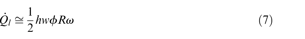
In the case of vehicular transmissions, generally the radial lip seals are mounted stationary in the gearbox housing. At the inner side of the seal, a rotating shaft seat is in contact with a non-rotating sealing lip. Between the contacting surfaces, a thin film of lubricant is formed of the transmission fluid with the rotation of the shaft. Poll and Gabelli 11 have obtained the thickness of the lubricating film by adding metallic particles to the lubricant and measuring the impedance of the lubricant layer. The impedance varies with the film thickness as the ratio of electrical voltage to the current intensity alters. For comparative purposes an analytical model was also developed to verify the experimental measurements. The idea of such an investigation was to relate the film thickness with the seal running condition. The extreme cases of untoward large film thickness, indicating impending leakage or very thin film indicating dry running were to be avoided.
The contact between radial leap seal and the shaft is subject to complex dynamic interactions and processes in real applications. These include the existence of radial vibrations, 12 due to effects such as shaft whirl. Measurements from a real vehicle by Nomikos et al. 13 indicate that likelihood of leakage increases with speed, coinciding with the resonant response of the system. This highlights the importance of vibration on radial lip seal performance. In addition, to the external dynamic sources, the interaction of real rough surfaces of radial lip seal and shaft is also transient in nature as noted by Salant, 14 also investigated through use of FEA methods by Hajjam and Bonneau. 15 This transient nature of lip seal and shaft contact conjunction gives rise to continual changes in surface topography, thus a spread of measured results for lubricant leakage. Vionnet 16 has also highlighted the importance of centrifugal instabilities as the driving force in the leakage from the radial shaft seals. Therefore, the flow through the gap is fully determined by axial pressure gradient induced by Taylor vortices on the oil side and by a quasi-hydrostatic air side pressure distribution. In addition, continuous wear of the radial lip seals is an important factor. The possibility of wear in such contacts can be high due to the existence of very thin gaps in the seal contact. Grun et al. 17 showed numerically the dominance of areas with positive wear orientation, indicating that the lip seal would be leakage proof. Burkhart et al.18,19 showed that there is a clear relationship between seal and shaft wear and that the shaft wear is caused also by a complex interaction between the lubricant and elastomer material.
Owing to the complexity of varying the seal running conditions, in-situ measurements and experimental evaluations are quite time consuming and usually prohibitively expensive. Therefore, available experimental results have been used to benchmark various numerical/analytical predictive methods and validate the same. 20 The numerical analysis methods have included various assumed regimes of lubrication, as well as the inclusion of roughness effects of the seal and/or the shaft.8,21–24
It has transpired that the sealing reliability of a gearbox is affected most significantly by the shaft’s surface texture and its lead angle (the machined lead angle). This finding is corroborated by much experiential observations in practice, so much so that standards such as DIN 3761-9, 25 ISO 6194-1 26 and RMA OS-1-1 27 have been set as guidelines for the determination and implementation of surface topography of radial shaft seals and the shaft lead angle. Clearly, conformance to these standards has manufacturing implications. Therefore, it is vital to determine the sealing performance, based on some measures of surface topography. The underlying supposition is that in practice, depending on the prevailing dominant operating conditions for a sealing system, there may exist an optimum surface topography. A suitable statistical measure of the topography may then be used to ascertain conformance of a manufactured/machined surface to the perceived optimum performance as well as to the aforementioned standards. Clearly, average surface roughness (Ra) is not an adequate measure of optimal topography for seals and shafts as noted by Qu, 8 who investigated various non-Ra statistical measures. It is clear that a lower value of the average roughness may affect the lubricant supply to the sealing lip or make it to bed-in incorrectly. On the other hand, rougher surfaces may promote excessive wear of seal lip and promote leakage. Kozuch et al. 23 showed through use of a hydrodynamic model that a shaft with a negative surface roughness skewness of its asperity heights tends to reduce the lubricant mass flow rate through the rotary lip seal subject to axial motion as a consequence of unwanted vibrations in a vehicular system. 13 Akkök 28 developed an elastohydrodynamic lubrication model of radial lip seals, using average flow Reynolds equation with flow factors for non-Gaussian surfaces based on surface roughness kurtosis and skewness. It should be noted that most engineering surfaces have asperity height distributions which are non-Gaussian. 29 Therefore, specific flow factors for these should be determined for measured surfaces29,30 rather than use of original Patir and Cheng 31 flow factors. Akkök 28 showed that for the same Root Mean Square (RMS) surface roughness and kurtosis, the leakage rate decreases for all values of skewness for tightly assembled seals. It is clear that analyses similar to Kozuch et al. 23 and Akkök 28 using a more in-depth statistical parameters integrated with a hydrodynamic or elastohydrodynamic analyses would form the basis for effective predictive models. To develop and validate such predictive analytical tools it is essential to generate sufficient rig-based experimental measurements under representative repeatable conditions. For vehicular transmission systems, there has been only very few such studies.
There have been several concepts in the development of test-rigs to study seal leakage. One of the oldest concepts was reported by Schuck 32 for testing of rotating eccentric and polygonal shafts. Another test-rig concept was introduced by Buhl, 9 who contrary to Schuck 32 kept a constant transmission fluid level by a permanent inflow through the driveshaft. Ruhl and Sauer 33 and Peteri and Sauer 34 introduced yet another approach, allowing oscillations of a hydropul cylinder in the rotating shaft as a measure of leakage. The leakage-induced hydraulic pulses help the analysis with full frequency spectrum of a rotary sealing ring without changing the shaft rotation. In a further step, Peteri and Sauer 34 improved their test-rig by adding a laser vibrometer to monitor the movement of the sealing lip relative to the shaft. The main approach of the leakage test-rig of Ruhl and Peteri 35 was to test rotary seal rings for a broad range of operating conditions and without any limitation regarding the used materials. A quick replacement of the test parts was not intended, and the used shaft was not comparable to those used in actual vehicular transmission shafts.
In the current study, in order to overcome the limitations of the aforementioned test-rigs and determine a more realistic behaviour of the test parts, a new test-rig is developed to operate with assembled parts used in an actual vehicle. The operation mode of the radial shaft seals, in combination with the sealing seat manufactured with different surface topographies, are compared using typical drive cycles of the investigated vehicle. The main aim is to establish whether a definitive link between a non-Ra surface topographical measure and seal leakage can be determined. It is also intended to provide much needed experimental data of vehicular transmission seal leakage for validation of models in the research arena.
Test-rig design
Figure 2 presents a schematic of the developed test-rig. The radial shaft seal test specimen resides in the flange (6) of a sump of lubricant, which represents the transmission housing. It forms the sealing system in combination with the sealing seat of the driveshaft (3). The shaft is driven by an electric motor (1), which generates the desired representative operating conditions of a vehicular gearbox. The driveshaft is supported by a bearing, mounted on the original bracket (16). The clutch (2) of the drive motor and the seat of the journal-bearing (7) are all positioned in the tank of lubricant. The sump is filled with the transmission fluid to any desired level. The sump is equipped with a heating element to bring the transmission fluid to the desired representative operating temperature. To record the measurement data, the test-rig is instrumented with several sensors, including a torque transducer and a number of thermocouples/thermistors.
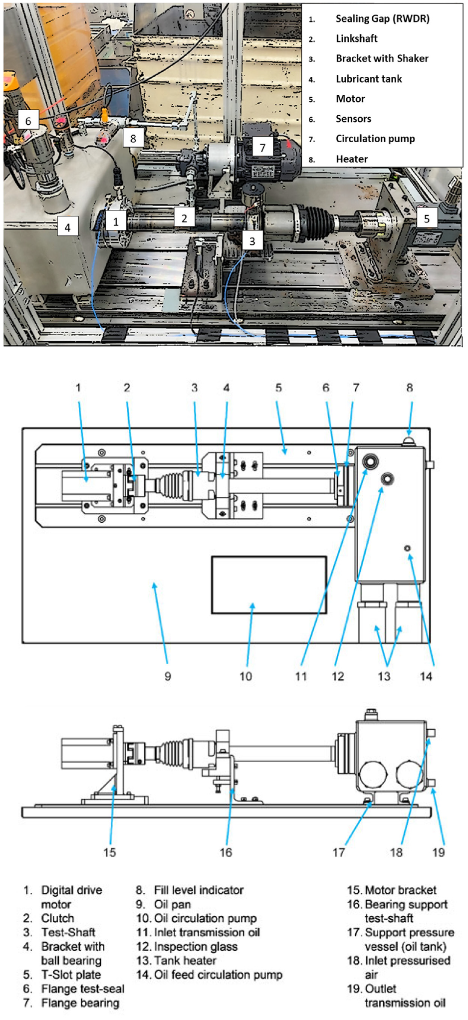
The developed test-rig and its schematic representation.
There are several prerequisites in order to carry out a realistic test, including maintaining a constant rotational speed of the electric motor, as well as predefined acceleration and deceleration ramps, representative of in-field vehicle manoeuvres. Furthermore, various constant lubricant operating temperatures with a steady fluid level should be maintained throughout an entire test run, as also noted in the standard DIN 8589-14. 36 The tank of lubricant is a welded pressure vessel, made from stainless steel. To measure the liquid level, an IFM LR2050 continuous-level (guided wave radar) sensor 37 was used. This sensor consists of an outer tube and a centred measuring bar on the inside. The height of the medium is measured using guided bi-directional microwaves. Electromagnetic impulses are emitted along the measuring bar, striking any medium stored in the pressure vessel. The impulses are reflected back to the fluid-level sensor. The sensor system measures the liquid level during the time it takes for the impulse to travel a certain given distance. Maintenance of a uniform temperature distribution is assured within the sump using a tank-heating system (13) and a lubricant circulation pump (10). As the driveshaft is powered through an electric motor (1) its rotational speed is programmable. It is also readily controllable for selected acceleration ramps. The driveshaft is pivoted in a changeable bracket (15) using the parts from an original donor vehicle. The variations in the applied torque between the sealing-seat of the driveshaft and the sealing-lip are measured by an integrated torque transducer with the electric motor (1). This ensures a compact design compared with the reported test rigs by Ott 38 or Heiland. 39 Torque measurements were performed using the control set (SINAMICS V90) of the motor. The controller operates in the torque control mode. Speed is monitored with a resolution of 20 bits or 1,048,576 pulses per revolution (PPR). The measuring range is 0.16–6.37 Nm at a maximum speed of 4000 RPM. The motor is directly connected to the component to be measured. The evaluation of torque takes place through use of measured electric current and voltage. Speed and torque control are integrated in the controller. For the rated torque, the rated power and the maximum torque a tolerance of 10% must be considered.
The sump uses an oil fill level indicator (8). As shown in Figure 2, the specific inlet (11) and outlet (19) ports enable easy adjustment for the lubricant level. It is also possible to generate an operational tank pressure through a compressed air connection (18). The build-up of pressure in the sump simulates the sealing pressure which occurs in a vehicle transmission during normal operation. The pressure differential across the seal is typically in the region of 20 kPa. 40
The amount of leaked transmission fluid can be determined through weighing blotting paper placed under the outer flange on the seals air side. All the measured data are collected, recorded and displayed by the control system.
The sealing system in Figure 3 is at the core of the test-rig. The sealing flange has a comparatively simple structure, the main components of which are its inner and outer flanges (5), (11). The sealing flange is mounted in the sump (1) and can easily be replaced when the application or the technical requirements change. In principle, the main task for the inner and the outer seal rings (2), (3) is to isolate the flanges from one another in order to avoid any loss of pressure. For the specific vehicle application simulated here, a journal bearing as in the case of the actual vehicle (4) is integrated into the inner flange (5). All the flanges comprise the same materials used in the donor vehicle. The sealing point is composed of a pairwise radial lip seal (8), the driveshaft (10) and the seat (9). The outer flange (11) is equipped with a specific sensor (6), capable of measuring temperature differences in the contact zone (7) of the sealing lip. Additionally, the control system can detect both the sump temperature on the oil-side and the environmental air temperature of the test-rig chamber on the airside (Figure 3). Apart from the mechanical and electronic design of the test-rig, a new test procedure is developed and implemented with the aim of achieving realistic and repeatable results.
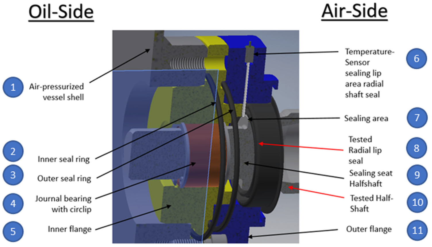
Inner structure of the sealing-flange.
Experimental procedure
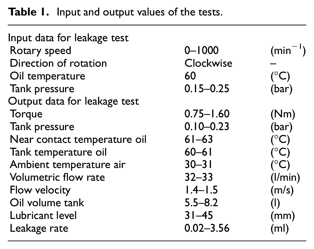
Standard cycles such as WLTP 41 are introduced for examining the combustion emissions and fuel consumption for vehicles, however, there is not any such standard cycle for examining the leakage from automotive transmissions. Therefore, the experimental procedure in this study is established, based upon the break-in cycle. The break-in-cycle introduces a repeatable running-in condition for both the shaft and the seal surfaces. During this phase the variations in applied torque over the time is recorded, with the aim of maintaining a constant rotational speed. All the important parameters are listed in Table 1, based on RMA OS 1-1 27 wherever possible. These are defined as input and output values for the test-rig operation. As also noted in the literature, the running-in period is essential for optimal rotary shaft seal operation. 42 The exact juncture, marking the culmination of the running-in stage of the sealing system can be recorded by the employed control system. 43 At this juncture, all the other measured and evaluated data are also displayed and recorded. These include the important indicator of the culmination of the running-in period, set as the Break-in-Point (BIP), which is characterised as a notable/measurable reduction in torque. This occurs owing to reduced friction because of smoothening of the counter face roughness in the shaft-seal conjunction. For the cases of the shafts, investigated in the current study, this point was achieved at different durations for each shaft.
Input and output values of the tests.
All the defined output values are recorded in real-time during testing using appropriate sensors. An overview of the output values is provided in Table 1. However, any leakage of transmission fluid is not directly recorded electronically. The amount of lubricant leakage can be accurately measured using blotting paper with a predefined weight. For this purpose, the blotting paper is placed in a special container under the outlet port of the sealing flange. Initially, the original weight of the paper was measured using a precision scale. Through the weight gained after a test-cycle the leakage can be expressed in ml of fluid. During the leakage-cycle all the measurements are stored and processed in real-time. Important measurements include variations in the rotational speed, changes in speed and torque over time and the temperature behaviour within the sealing zone. The measured torque includes the frictional torque produced between the seal and the shaft, as well as any frictional torque generated in the bearings. In order to isolate the frictional torque between the seal and the shaft, a number of shafts were run without an attached seal. This allowed measurement of an average value for the frictional torque of the bearings, which is then deducted from the measured overall torque during the leakage measurements. In addition, the oil sump temperature, the sealing pressure and the oil-level in the tank are monitored. Other parameters include the temperature of the test cell (i.e. the surrounding air) and the flow rate of the transmission fluid. To determine the flowrate and temperature of lubricant an IFM SA2000 flow sensor, 44 operating on calorimetric measurement principle, was chosen. In this measuring process, a constant temperature difference occurs between a temperature sensor tip, warmed up by a heating element periodically and the surrounding unheated stagnant medium. Only when the surrounding unheated medium starts flowing around the sensor a temperature difference occurs through absorption of thermal energy. This temperature difference increases proportionally to the flow rate. Therefore, with appropriate calibration, the flow rate can be determined through measuring the temperature difference.
Characterisation of the shafts
In the current study the leakage behaviour of link-shafts is considered of primary concern. Such shafts are inboard-joints which transfer the force from the differential to the wheel-hub in cases that the vehicle engine is not centrally located. Through the elongation of an inner joint an appropriate movement can be accommodated. An example of a link-shaft to be tested for its leakage performance is shown in Figure 4. The sequential manufacturing process is also illustrated by the flow-chart in the same figure.
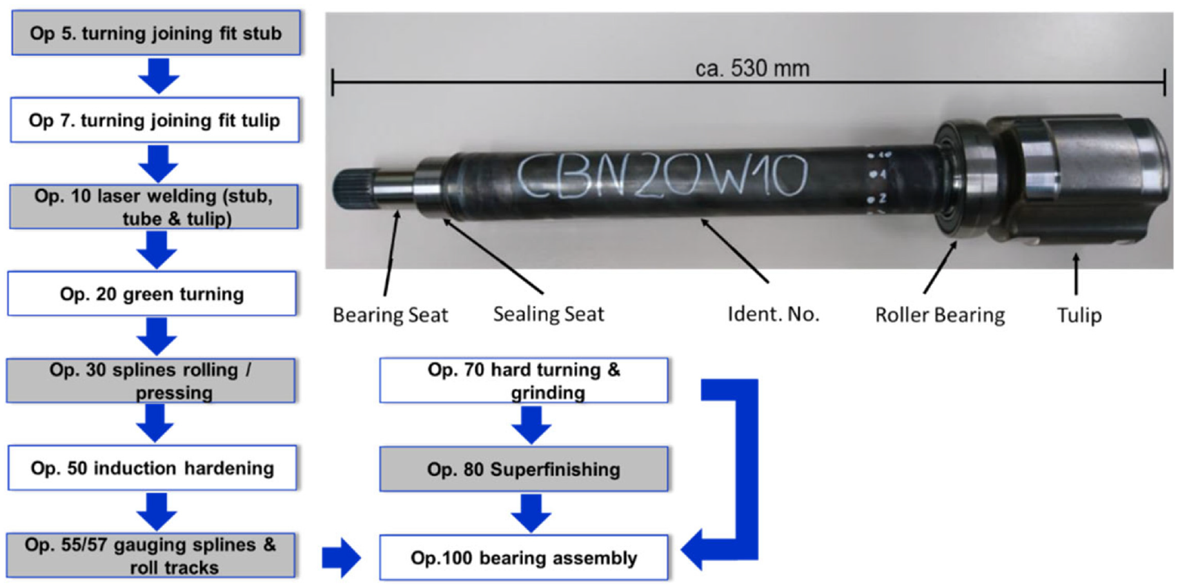
An example of CBN-ground link-shaft.
The test shaft specimen has an approximate length of 530 mm with its sealing surface turned down to a diameter of 40 mm. At one end, the shaft contains a plug-in spline, which provides the power transmission between the differential and the outboard joint. At the centre of the shaft, an identification number is incorporated, following which the sealing seat is ground by the CBN (cubic boron nitride) grinding process.
The abbreviation CBN20W10 stands for a CBN ground shaft, which is subjected to a running-in test-cycle of approximately 20 h. In total 50 CBN ground shafts and 50 Corundum ground shafts were initially planned to be tested for their leakage performance. In real vehicle application, a rolling element bearing is attached to a bracket, which is fixed to the underbody of the vehicle. At one of its ends, a tulip (more precisely, a tripod synchronous displacement joint) is situated. Through this tripod joint length compensation for any axial displacement can be accommodated.
The surface roughness of the counter face for the radial shaft seals is determined in accordance with the standards ISO 4288 and DIN 4768.45,46 This should be kept within the limits specified in RMA OS-1-1 27 with a surface topographical quality of Ra = 0.2–0.5, and Rz = 1.2–3.0 µm.
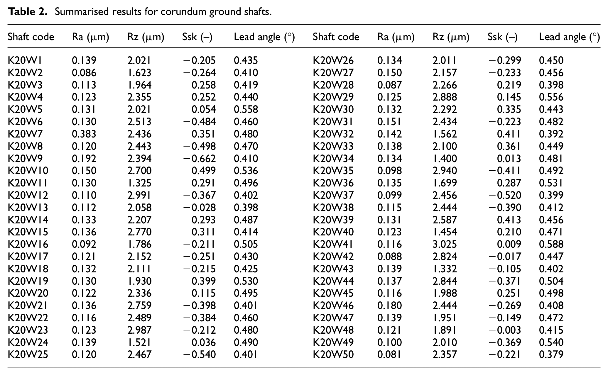
In the first column of Table 2, the topographical information including
Summarised results for corundum ground shafts.
The measured surface quality of the shaft sealing seats for
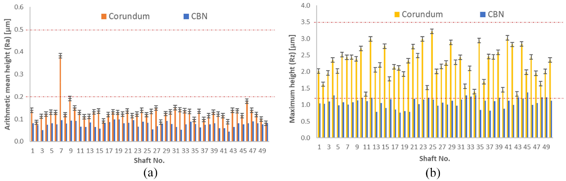
Measured (a) Ra and (b) Rz.
Radial lip seal
An example of radial shaft seals used during the experiments is shown in Figure 6. This type of seal is coated before the test-runs with a sealing paste pressed onto the test flange of the rig. This action is essential in order to ensure that no lubricant can ingress in between the outer diameter of the rotary shaft seal and the inner diameter of the test flange. The rotary shaft seal is equipped with a reinforcing ring, containing an elastomeric sealing material. Each sealing ring is greased to prevent a dry run-in start-up or stop conditions. For each test-run a new sealing ring is paired with a new shaft.
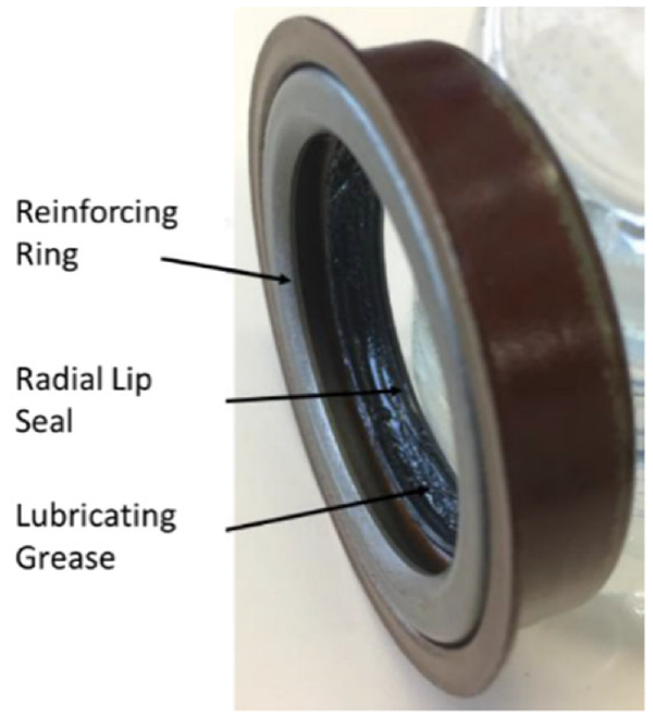
Radial lip seal ANIS-1177-1 543 933.
To measure the roughness parameters of the sealing lip, a Keyence confocal 3D laser scanning microscope was used. With this measuring device, magnifications of 2.5× to 150× are achievable. The sealing lip of the rotary shaft seal was examined at 20× magnification, with a measured (scanned) area of 532.65 µm × 710.70 µm. Prior to measurements, the sealing lip was prepared on a microscope glass slide. For this purpose, a cut-out piece of the sealing lip is affixed in an unrolled form to the microscope slide. The sealing lip is oriented under the microscope such that the surface to be measured is horizontally positioned under the laser. The scanned surface is processed in the device analysis software to evaluate the roughness parameters. In case of an uneven orientation, the surface to be measured can be straightened for correcting a possible inclination. Figure 7 shows a cross-sectional profile of the lip seal, measured using the Keyence Alicona Vision System. Using this profile, it is possible to calculate the radius of curvature of the seal lip which can then be used to obtain the seal contacting face-width.
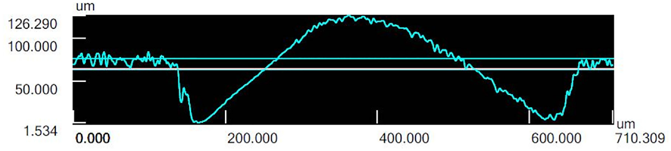
Measured lip seal profile.
Figure 8 shows the topographical features of the lip seal surface under 20×, 50× and 100× optical magnifications, measured using an Alicona infinite focus white light interferometer with a measurement resolution of 10 nm. The local undulations on the seal surface are quite visible in the acquired images.
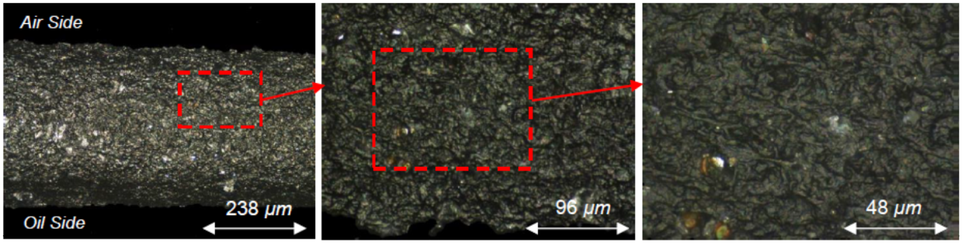
Topographical surface features of the lip seal under 20×, 50× and 100× optical magnifications.
Sealing fluid
All tests were performed with the transmission lubricant; Titan Sintofluid FE SAE 75 W, which is also used in the actual transmission of the test vehicle (simulated with the developed test-rig). The lubricant dynamic viscosity variation with temperature is shown in Figure 9. For this purpose, a U-tube viscometer was employed. To measure viscosity at different temperatures the U-tube viscometer was submerged into the tank of fluid containing an electrical heating element. After the tank temperature reaches a prescribed steady-state level, the time taken for the lubricant to flow within the U-tube viscometer between two fixed points is measured. This procedure was repeated five times at each temperature and the average value were noted. The kinematic viscosity of the lubricant was obtained based on multiplying the time taken in seconds to the viscometer constant. To measure the density of the lubricant at each temperature, the heated lubricant was poured into a 15 cm3 volumetric flask and its mass was measured.
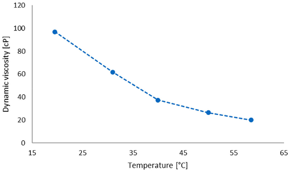
Measured dynamic viscosity of Titan Sintofluid FE SAE 75 W at different temperatures.
Experimental results and discussion
Prior to the commencement of tests, the surface topography of all the link-shaft specimens were measured, as well as their lead structures. The shaft surfaces are specified according to DIN 3760 47 and DIN 3761. 25 Characterisation of the surfaces by the topographical parameters Ra and Rz is well-established. Ra is defined as the arithmetic average of the absolute values of the asperity height deviations from the mean height line located in the evaluation length of the test sample. 48 It provides no information about the highest peaks or the deepest valleys. On the other hand, Rz is a measure of the vertical height distance from the highest peak to the deepest valley within five averaged sampling lengths. 48 It provides no information about the natural profile of a machined surface. Nevertheless, these are the most commonly used topographical parameters in practice. For the variously ground shafts (CBN or corundum), the resulting topographies (i.e. Ra and Rz) differ. During the tests it was found that the sealing performance of the link-shafts varied considerably with the method of surface finishing, based on the use of corundum or CBN tools. The CBN ground shafts showed no leakage for the duration of the tests, whilst it was possible to measure noticeable amounts of leakage for the corundum ground shafts, as almost all of them produced some degree of lubricant leakage.
The leakage from the shafts during the break-in cycle was considered for the experiments. This is also in line with the current research objective, which intends to examine any potential correlation between the measured leakage and the shaft surface topographical parameters as obtained from the production line. Since the surface topography of the shafts alter during the break-in period, the measured leakage from the break-in period is deemed more suitable for investigating the existence of any potential correlation with surface roughness parameters.
Figure 10 shows a typical example of measured torque data for the duration of operation including the data for the maintained shaft speed and measured temperature. The break-in point is considered to be the moment when the initial high torque falls to a minimum, after which the torque remains largely settled and thereupon does not show any significant variation. Based on this premise, the torque break-in point for the given example in Figure 10 is considered to be at around 337 min.
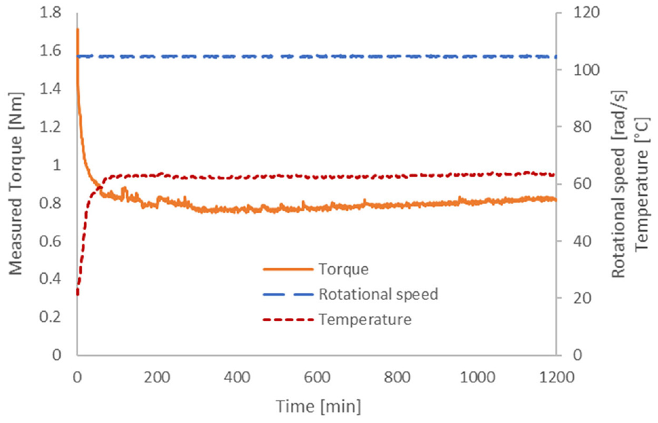
An example of monitored torque, speed and temperature variation during the tests.
The measured leakage value for each tested corundum ground link-shaft is shown in Figure 11. It is also observed that most leakage occurs during the initial break-in period, after which the leakage rate is significantly reduced. However, because the monitoring of leakage was not automated, all the shafts were exposed to a 20-h period of break-in process in order to ensure that all shaft surfaces have reached their break-in points.
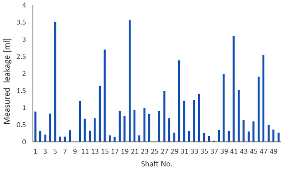
Measured leakage from all corundum ground shafts.
Based on the results for the corundum ground shafts, no specific quantitative correlation is found between the measured leakage and surface topographical parameters; Ra and Rz as well as with the lead angle, as can be seen from Figure 12(a) to (c). This can be further verified by determining the standard Pearson correlation coefficient for the presented measurements. A correlation coefficient between the measured leakage and the Ra, Rz and lead angles are obtained as 0.016, 0.174 and 0.300, respectively, indicating existence of no or very weak correlations.
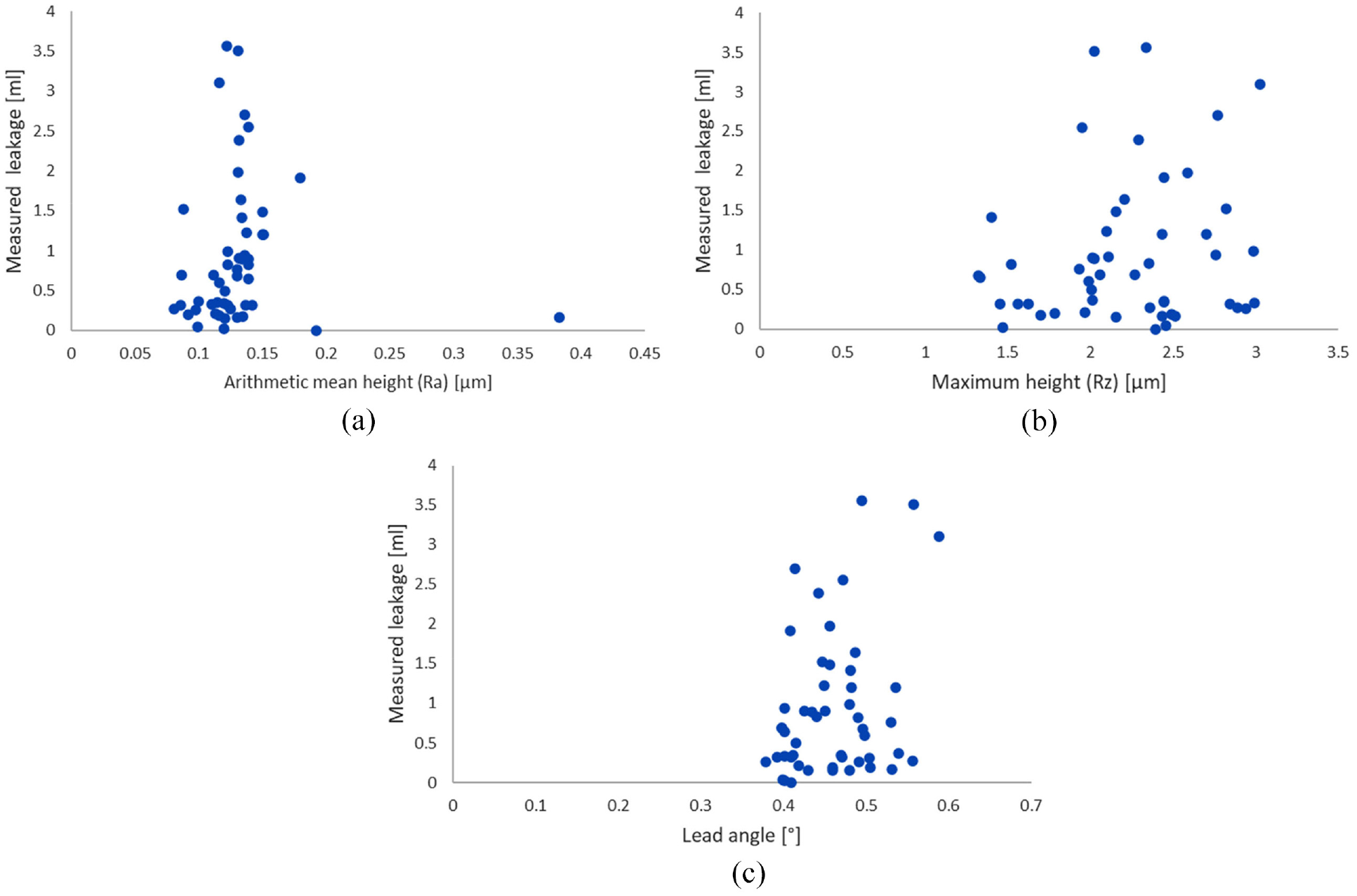
Measured leakage against (a) Ra, (b) Rz and (c) lead angle for corundum ground shafts.
These findings are in line with those of Qu 8 and Kozuch et al. 23 who considered non-Ra parameters.
Generally, plunge grinding is a preferred machining method in order to minimise the directionality of the seal counter face. Depending on the attitude of plunging, the lead angle becomes the dominant surface structure/texture which can also distinguish corundum and CBN manufacturing processes. The corundum-ground shafts show a screw-like surface structure/texture, depending on the feed of the grinding tool. On the contrary, CBN ground sealing areas have a linear direction and do not show any notable surface texture with any specific orientation. 49 Therefore, only the corundum ground shafts show periodic swirl structures or leads, which was also noted in,50,51 generating a mass flow in relation to the direction of rotation of the shaft rather similar to an Archimedean screw.
The standards suggest acceptable lead angles in the range of 0°–0.05°. As it can be seen from Figure 12(c), the lead angles for the corundum shafts exceed this range. Therefore, it is expected that the existence of such patterns can contribute to the observed leakage from those shafts. However, as it is clear from Figure 12(c), it is very difficult to establish a correlation between the measured leakage and the lead angles, particularly that the range of variation of the lead angle values is relatively limited.
This points to the use of more suitable parameters for non-Gaussian surfaces, including for correlative studies of experimentation and for numerical analysis as noted.29,30 Therefore, it was decided to identify other more suitable surface parameters which would potentially influence the tightness of a sealing system.
In contrast to Ra and Rz, the current study focuses on an important surface areal parameter; skewness, Ssk. Previous studies have suggested that skewness may be directly correlated to seals leakage performance.23,52 A 3D topographical skewness is denoted by Ssk, which indicates the degree of symmetry of the 3D surface elevations around its centre plane, determined as 53 :
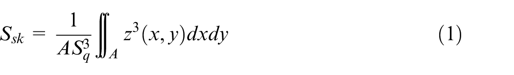
where, z (x, y) are the asperity peaks of a rough surface relative to the best fit plane or sphere.
Generally, a positive skewness value is an indication of the dominance of the peaks in a measured profile, whilst a negative value indicates the dominance of the valleys in the measured profile. In-field experience shows that the link-shafts complying with the standard specifications stated for Ra and Rz still result in leaking seals.
The results for measured leakage against skewness are shown in Figure 13. Figure 13(a) shows that there is a trend in the presented data. The calculated Pearson correlation coefficient shows a value of 0.538, indicating the existence of a reasonable correlation between the measured leakage and the shaft skewness. There is a larger spread in the leakage for shafts with positive skewness value as can be seen in Figure 13(b). In addition, Figure 13(b) shows that the overall average leakage for negatively skewed shafts is lower than that for the positively skewed shafts. It also seems that the likelihood of leakage increases for negatively skewed shafts with a reduced skewness magnitude. This is evident by comparing the average measured leakage values for shafts with negative and positive topographical skewness as shown in Figure 13(b). Conducting a t-test for the data shown in Figure 13(b), results in a t-value of 4.92, which is greater than t-value of 2.02, based on typical 5% alpha confidence level for 48 degrees of freedom obtained from t-distribution table. Therefore, the null hypothesis that there is no difference between the two average values shown in Figure 13(b) because of any standard deviation overlap can be rejected.
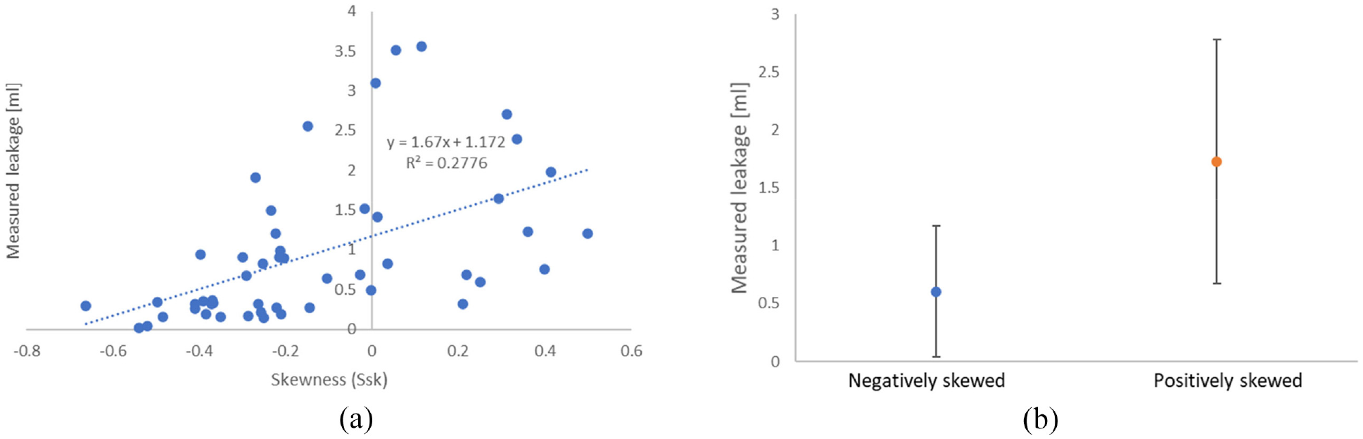
(a) Measured leakage variation with skewness for the corundum ground shafts and (b) average measured leakage for negatively and positively skewed shaft surface roughness.
The measured skewness of the corundum shafts is compared with those of their CBN counterparts, with the latter showing insignificant measurable leakage for the tests. The results for the measured skewness values are shown in Figure 14. As it can be observed, there is considerable difference between the measured skewness values for the CBN and corundum ground shafts. On average, based on the trend lines shown in the figure, the skewness values for the corundum ground shafts are more than fivefold smaller.
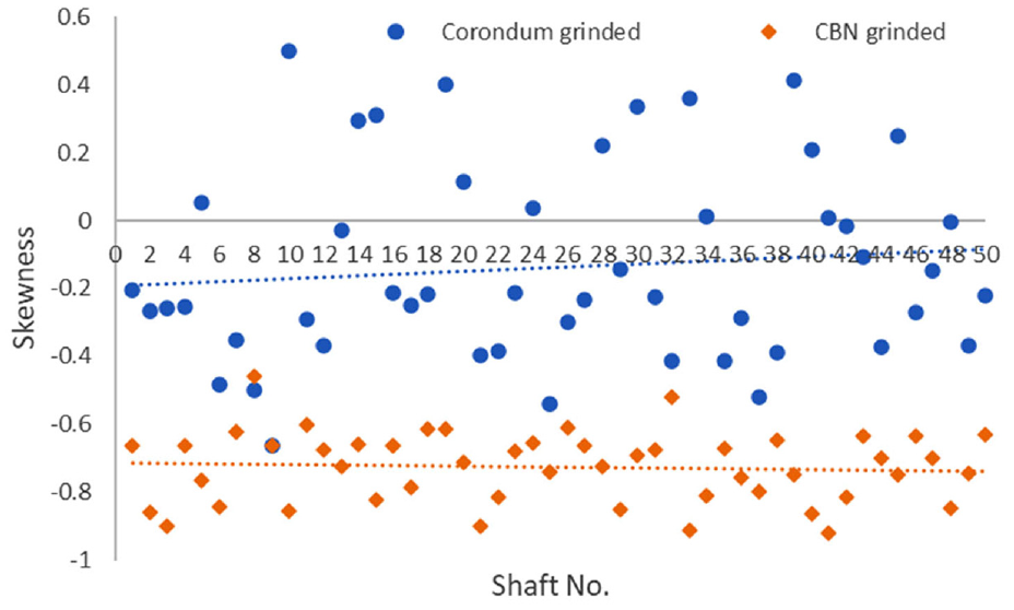
Measured skewness values for both corundum and CBN ground shafts.
Therefore, the results in Figure 14 along with the leakage data shown in Figure 13 suggest that there is a good correlation between surface roughness skewness and lubricant leakage.
Negative skewness values indicate the dominance of the troughs or valley in the surface topography, which may act as micro-reservoirs/micro-pockets retaining volumes of lubricant at high local pressures which may act as barriers against leakage. This is in line with the observations made for textured surfaces in the study of mechanical seals. 54 Therefore, the results for higher negative skewness values indicate increased lubricant retention capacity with lubricant entrapment in the contact area. These also reduce the extent of direct surface interactions, thus palliate the severity of boundary regime of lubrication in a similar manner to surface texturing of seals, bearings and other tribological conjunctions.20,55–57 However, the increased depth of valleys (i.e. the gap in the sealing conjunction), if uncontrolled can also promote increased leakage. This is also noted for some textured surfaces under various operating conditions.58,59 In the case of texturing, texture depth, shape, spacing and distribution can be used to optimise lubrication conditions, whilst minimising leakage. 60 However, the same cannot be assured for ground surfaces which have a fairly random topography. Therefore, it is important to arrive at an optimum solution, first by establishing a correlated link between a statistical measure of topography (such as skewness) and leakage, and second by specifying a surface finishing process to achieve the same.
Analytical assessment of the results
To estimate the leakage from the radial lip seal, the gap between the lip and shaft must be determined. Horve 61 has proposed the well-known Petroff equation, commonly used to calculate friction in journal bearings to approximately determine the film thickness if the frictional torque is known. The proposed model was also used by Kammüller 62 and Van Leeuwen and Stakenborg 63 for estimating the frictional torque of radial lip seals:
where,
To account for the potential contribution of the asperities in the contact to generated friction, the total torque can be written as contributions due to viscous shear of a fluid film and the asperity interactions:
where,
where,
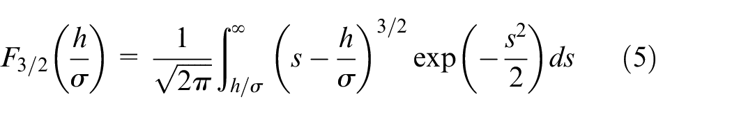
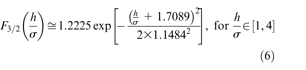
A Gaussian distribution fit of the above function provides the following convenient approximation:
Subsequently, solution of equation (3) can provide an estimation of the film thickness in the contact.
Once an estimate of the lubricant film thickness is made, the leakage flow rate can be calculated. There are two orthogonal flows inside the lip seal contact. One is along the shaft’s axial direction due to pressure gradient, whilst the other is in the circumferential direction in the form of Couette flow. Neglecting the effect of geometrical design features on some radial lip seals which allow promotion of reverse pumping, the existence of pressure gradient in the axial direction is expected to result in the leakage flow through the seal contact. This is, to some extent, analogous to the leakage of lubricant from journal bearings with the exception that the leakage taking place through the air side is of concern in this case. Thus, the flow rate can be approximated as:
where,
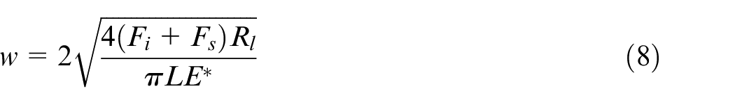
The seal contact face-width in the axial direction,
where,
With the contact face-width obtained from equation (8), equation (3) can be solved for an average contact lubricant film thickness, and subsequently the leakage flow rate can be estimated using equation (7). A list of input data for the model is provided in Table 3.
List of input data.
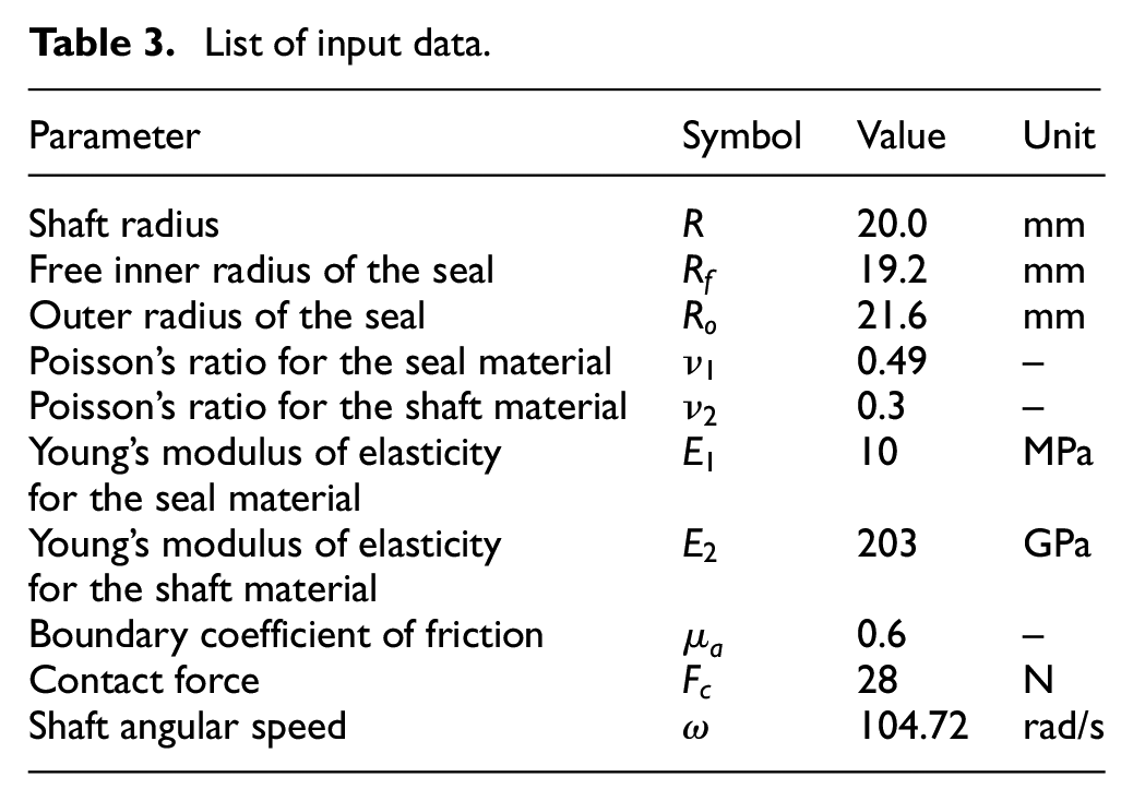
Figure 15(a) shows the ratio of boundary contribution to the total frictional torque for a range of rotational speed and film thickness values. These predictions show that overall contribution of boundary friction reduces with rotational speed and/or film thickness as expected. However, the results in Figure 15(a) also show that there is a film thickness, independent of rotational speed, where the contribution of boundary friction attains its maximum value. The value of this specific point depends on a number of parameters, but mainly on the shaft surface roughness. Existence of this peak is related to the difference in the rate at which the frictional torque due to viscous shear of the lubricant film and that of asperity interactions rise or fall with film thickness, based upon the equations used. For the studied cases here, the contributions from the boundary friction remain below 18% of the total and is expected to reduce further with increasing rotational speed. Figure 15(b), on the other hand, shows the predicted leakage mass flow rate for the same speed and film thickness range. These predictions show that if the rotational speed during the tests increases, the leakage rate would also increase accordingly irrespective of the size of the gap. However, the leakage would be higher for the shafts having a larger gap size.
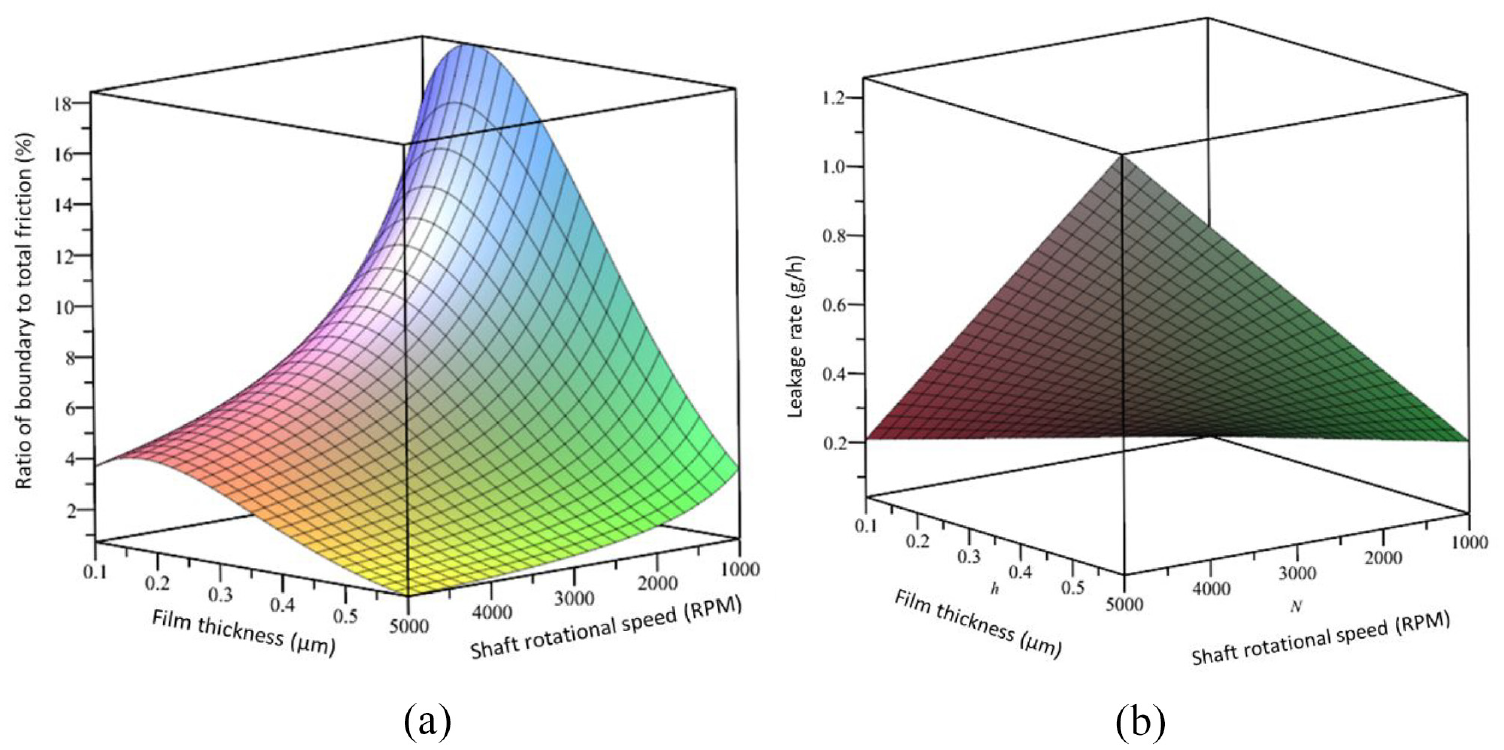
Predictions: (a) contributions from boundary friction and (b) leakage rate.
Figure 16 compares the predicted leakage using the analytical model with those directly measured. Considering the simplicity of the model used, it is noteworthy that reasonable order of magnitude agreement exists between the predicted and measured data. The best fit trend lines in Figure 16, shown for both the data sets corroborate this despite the existence of individual differences between the predicted and measured leakages for each shaft. As expected, it is difficult to make a direct comparison between the individual points as the simple model used here does not take into account many details related to the topographies of the seal and the shaft. However, it is quite remarkable that the trend lines for both set of data correlate quite well.
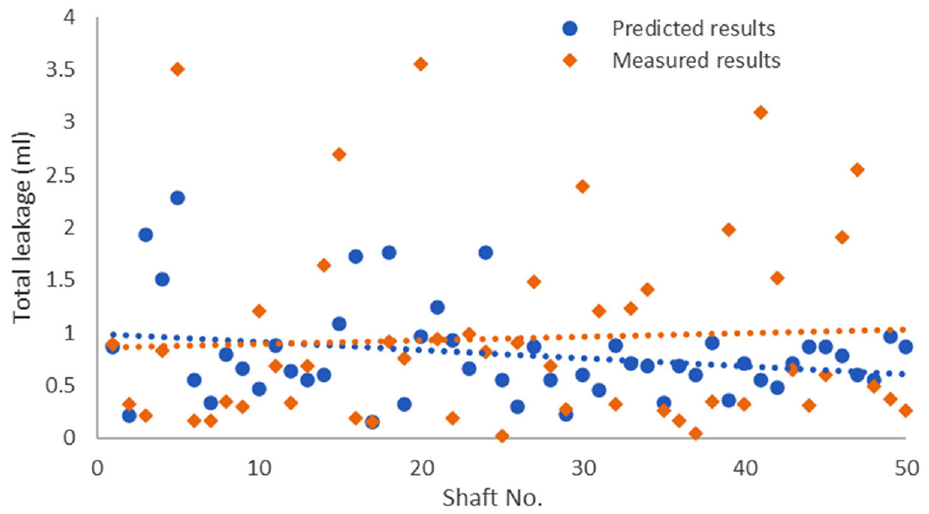
Comparison of predicted and measured leakage values for all shafts.
A more accurate examination of the effect of surface topography on the predicted leakage would require the development of detailed numerical models for lip seal-shaft contact, including surface roughness effects. This is beyond the scope of the current work. However, at this point it would be interesting to examine the influence of shaft skewness on the predicted results through a correction factor. This approach enables the determination of any positive effect that the surface skewness of shafts may have on the corroboration of the corresponding data between the experiments and analytical predictions. For this purpose, the correlation shown between the measured leakage quantities and the shaft skewness in Figure 13(a) is used. Then, the predicted leakage from equation (7) is scaled, based on the curve fit equation presented in Figure 13(a) describing the observed trends between the measured leakage and skewness of the corresponding shafts:

The results are compared in Figure 17. Figure 17(a) and (b) show that the spread of the data around the best fit trend line is significantly reduced when including the topographical correction factor, based on the shaft surface skewness. It is noteworthy that a similar attempt was made based on correction factors obtained using other surface topographical statistical measures such as the arithmetic mean surface height or the maximum height. In all such cases the spread of the data around the original trend line in Figure 17(a) was in fact increased even further. Therefore, skewness seems to be the appropriate correlative topographical parameter with seal leakage.
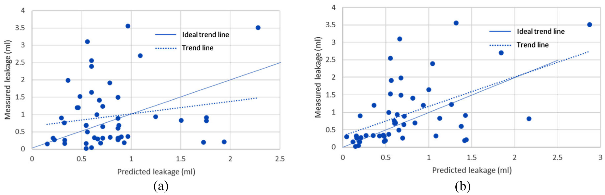
Measured leakage versus (a) predicted leakage and (b) scaled predicted leakage including shaft surface topographical skewness.
Concluding remarks
The paper investigates the influence of statistical surface topographical measures of link-shafts of vehicular transmissions upon leakage of lubricant from radial lip seals. Surface finishing manufacturing methods such as corundum or CBN grinding, commonly used for the seal link-shafts, affect the leakage from the sealing system. Differences in leakage between the various surface finishes have been noted in practice, but a fundamental combined analytical-experimental investigation has not hitherto been reported. This has been because of a dearth of experimental data and particularly representative test rigs. The paper reports on the development and use of a specifically designed and fully instrumented test-rig to investigate leakage from radial lip seals used particularly in automotive power transmission units. The test-rig uses a real link-shaft and seal from automotive transmission system and is able to subject the seal contact to actual operating conditions in terms of speeds, temperatures and oil pressure conditions, which occur in real applications. To the best of authors’ knowledge, there is no specific and widely accepted standard test protocol for assessing the performance of radial lip seals used in the automotive transmission systems, which can reflect the real working conditions. Therefore, to assess any potential relationship between the leakage and the surface topography of the shafts, the shafts were subjected to a standard break-in cycle. Two sets of shafts, machined using CBN and Corundum grinding techniques, were tested. It was observed that the CBN ground shafts promoted insignificant leakage while the corundum ground shafts were prone to leakage.
An investigation of the surface topography of the shafts showed that Ra and Rz statistical topographical measures do not correlate well with the measured leakage from corundum ground shafts, thus much of the existing standards do not fully define suitable shaft surface roughness characteristics. However, it is essential for seal manufacturers to determine suitable correlative topographical measures and representative values of the same to guide methods of surface treatment to achieve optimal sealing performance. The current study shows a good correlation between the volume of the leaked oil and the skewness of the shaft surfaces profiles. It was observed that all the CBN ground shafts exhibited negative skewness values, while the corundum ground shafts had either positive or reduced negative skewness. It was also observed that, on average, the corundum shafts with negative skewness leaked less than those with a positive skewness value. Such detailed investigation of the specific shaft roughness effects, particularly considering the surface topography skewness, has not hitherto reported in the literature.
To assess the experimental data a basic analytical model is developed and used, showing good trend-wise corroboration with the measured leakage from the test-rig. Since the analytical model does not include salient information about shaft roughness, a scaling method based on the curve-fitted linear relationship between measured leakage and shaft skewness was used, the result of which shows enhanced quantitative agreement between the predicted and measured leakage data. Clearly, with significantly improved availability of representative measured leakage data, the opportunity now exists for more detailed numerical analysis of real rough automotive radial lip seal contacts under mixed regime of lubrication. It is also hoped that the work presented here would be further expanded by including additional test samples, which would be manufactured through different machining methods. This would enable a better understanding of the effect of various manufacturing techniques on the performance of the machined shafts.
Footnotes
Appendix
Declaration of conflicting interests
The author(s) declared no potential conflicts of interest with respect to the research, authorship, and/or publication of this article.
Funding
The author(s) received no financial support for the research, authorship, and/or publication of this article.