
Abstract
Dehumidification and heating of electric vehicle heat pump systems are of significance in ensuring comfort and safety in winter. This study purposes to investigate the dehumidification and heating performances of a new-designed heat pump system. A numerical model is established and serves for analyzing the ventilation conditions for dew or fog removal of the windshield. Both ventilation conditions of the heat pump and the inner surface temperature of the windshield were investigated as per experimental measurements. Meanwhile, dehumidification rates, effective heating capacity, and coefficients of performance were analyzed under different operating conditions. It is shown that the heat-pump’s air outlet conditions are within the range of suitable ventilation conditions meeting the needs of dew or fog removal. At the same compressor speed, the inlet air humidity of the evaporator inlet decreases, the dew or fog removal is more effective, and the coefficient of performance for heating increases but the coefficient of performance for dehumidification decreases. In the case of the same inlet air humidity, the dew or fog removal effect is better with increasing compressor speed; Meantime, the coefficient of performance for heating and dehumidification both decrease. The lower compressor speed and lower inlet air humidity for the evaporator enable the heat pump system to meet the demand for dew or fog removal of the windshield and ensure thermal comfort in the cabin. This study verifies the effectiveness of heat pump systems for dehumidification and heating and would be valuable to promote heat pump systems.
Highlights
A heat pump system for dehumidification and heating is presented.
Suitable ventilation conditions for dew or fog removal are analyzed.
The effectiveness of heat pump systems for dew or fog removal is verified.
Dehumidification and heating performances are analyzed in various operations.
Introduction
The strong promotion of electric vehicles is considered a major measure to alleviate environmental and energy shortage problems. 1 Technologies related to the comfort, safety, and energy efficiency of electric vehicles have received widespread attention. 2 The cabin thermal management system is an important part of the vehicle, guaranteeing passenger comfort and ensuring safe vehicle operation through functions such as cooling, heating, dehumidification, and defogging.3,4 In winter, windshield dewing and fogging are common, which can affect the sight of the driver. Higher humidity inside the car can affect the comfort of the occupants and the stability of electronic equipment. Unlike conventional internal combustion engine vehicles, electric vehicles do not have waste heat from the engine available for heating and reheating after dehumidification. In recent years, heat pump technology applied to electric vehicles has attracted a lot of attention. It is essential to study the dehumidification and heating performance of heat pump systems in winter. However, there are more studies on heat pump heating performance and fewer studies involving dehumidification.5–8
Efficient dehumidification systems or methods have been explored in many recent studies. Yang and Yang 9 investigated the system performance of a new pressurized dehumidification air conditioning system, which uses an air cycle refrigerator and a desiccant wheel to regulate air temperature and humidity simultaneously. The investigation results indicated that the system can perform efficient dehumidification within a wide range of ambient temperature and humidity. Wang et al. 10 proposed and experimentally studied a partial air dehumidification and drying heat pump system. Under the set air supply condition, the average COP of the heat pump system was 3.58, and the average specific moisture extraction rate was 2.282 kg/(kW·h). Yang et al. 11 designed a two-stage evaporative cooling system using composite activated carbon fibers for dehumidification. The high humidity air after the first-stage evaporative cooling is dehumidified in the internally cooled desiccant bed before the second-stage cooling. The performance experiments of the two-stage evaporative cooling system showed a lower supply air temperature and humidity ratio than the single-stage system, and a significant improvement in system energy efficiency. Electric vehicle heat pump systems are generally more compact and rely mainly on the evaporator for cooling and dehumidification. There are relatively few studies exploring the dehumidification and heating performance of electric vehicle heat pump systems in practical application scenarios.
Utilizing return air from the cabin for heat pump heating is an efficient way to save energy because it reduces the heat load and thus increases energy efficiency.12,13 However, high humidity of return air still causes the windows to dewing or fogging. Therefore, it is important to study the appropriate return air ratio.14–16 Zhang et al. 14 proposed the concept of applying a continuous anti-fogging air curtain on the front windshield to achieve maximum return air utilization in winter. The results showed that when the return air ratio is 0.46, the highest coefficient of performance is 1.57, which is 12.1% higher than the all-fresh air operating condition. Liu et al. 15 conducted an experimental and numerical simulation study on the fogging characteristics of electric vehicles and improving the return air utilization. A part of the results obtained from the experiments was taken to improve the thermal-humidity model. Additional experimental test results were compared with the model simulation results showing errors below 10%. Pan et al. 16 performed a study on the energy-saving effect of recirculated air in an air conditioning system of an electric vehicle. The fresh air rate based on CO2 limits and windshield anti-fogging requirements was calculated. The results showed that the utilization of recirculated air throughout a year can increase driving range by 11%–30%. In the above studies, removal of the dew and fog can indeed be achieved by mixing indoor return air with outdoor fresh air and then heating it through the condenser of the heat pump system. However, if the moisture is not removed but recirculated into the car, the moisture content in the car will still be higher and higher as the human body disperses moisture. For heat pump systems, the dehumidification method, and the energy efficiency of dehumidification and heating, both need to be studied.
Utilizing a heat pump system with a desiccant-coated heat exchanger to accomplish dehumidification is one option. Zhang et al. 17 proposed a heat pump system with integrated desiccant, which can reduce the fresh air rate and cabin heat demand after completing dehumidification. The results showed that the cabin heat load and the compressor power were reduced by 42% and 38%, respectively, at the ambient temperature of −20°C compared to a conventional electric vehicle heat pump without returning air. Na et al. 18 proposed a scheme of vehicle thermal management systems. The humid air was pretreated by the desiccant-coated heat exchanger in the coolant circuit and then heated by the condenser in the heat pump system. The simulation results showed that the proposed system consumes less energy than the conventional system. Na et al. 19 further proposed a continuously operable system applying double desiccant-coated heat exchangers. They developed a comprehensive numerical model of the cabin heat load model, the desiccant-coated heat exchanger model, and the heat pump system model, and experimentally validated the numerical model. The study results showed that the proposed system consumes less energy than the system with a single desiccant-coated heat exchanger. Wang et al. 20 studied and analyzed the dynamic performance of a multi-stage dehumidifier plate air dehumidifier. The optimum numbers of dehumidification plate stages for different operating conditions were explored aiming at reducing the proportion of ineffective sections and increasing the effective working time. The upgraded multi-stage dehumidification plate device could effectively extend the working time. Zhao et al. 21 summarized the current status of investigation and application concerning desiccant-coated heat exchangers. They elaborated on the superiority of desiccant-coated heat exchangers in the dehumidification principle and introduced the research status of desiccant-coated heat exchangers from four aspects, including desiccant coating, cooling source, regenerative heating source, and basic heat exchanger. However, it is a great challenge to coat the existing compact heat exchanger with desiccants. The reliability of coating materials is difficult to guarantee. In addition, the alternate operation of the adsorption and regeneration process is not conducive to the continuous and stable operation of the vehicle thermal management system. The regeneration process needs to consume additional heat, which also makes the system structure more complex.
In a vapor compression system, the evaporator is often used for dehumidification. A heat pump system with three heat exchangers typically has an indoor evaporator, an indoor condenser, and an outdoor heat exchanger. 22 The indoor evaporator and condenser can dehumidify and heat humid air successively. There are few studies on the dehumidification and heating of this kind of system. The suitable ventilation conditions of the heat pump for dew or fog removal in different situations also need to be studied. It is also essential to explore the dehumidification and heating characteristics of such systems.
In this work, the dehumidification and heating performance of a self-designed heat pump system was experimentally studied. Based on the requirements of dew or fog removal, the suitable ventilation conditions were firstly analyzed. Then, an experimental bench was established to study the variations in dehumidification rate, air outlet temperature, air outlet relative humidity, and coefficient of performance under different operating conditions. Moreover, the dehumidification and heating characteristics were discussed under variable inlet air humidities (fresh air ratios) and compressor speeds.
Experiments
Ventilation conditions for dew and fog removal
Electric vehicles typically have the Heating Ventilation and Air Conditioning (HVAC) module with blowing face, blowing foot, and defogging modes. 14 In the defogging mode, the HVAC module blows hot air treated by the heat pump to the windshield while also meeting the heating demands of the cabin. During the driving of a vehicle in winter, if the inner surface temperature of the windshield is lower than the dew point temperature of the nearby air, dew and fogging will be observed. At this time, the HVAC module switches to defogging mode to complete the requirement of rapid defogging. The ventilation conditions during the defogging mode need to be studied. Taking windshields as the object of the study, a heat transfer model was developed to analyze the appropriate ventilation conditions. Figure 1 shows the ventilation schematic when the windshield is in defogging mode.
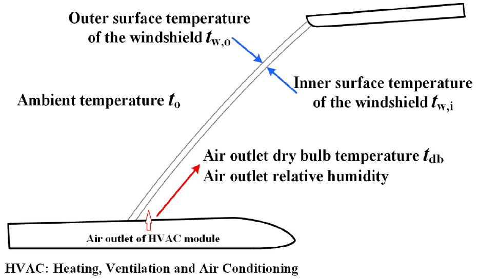
Schematic diagram of windshield ventilation.
When the vehicle is driving, the flow fields inside and outside the cabin are complex, making it difficult to accurately analyze the heat transfer near the windshield. There will be local differences in convective heat transfer coefficients. In some engineering cases, some empirical correlations are often used to calculate some parameters that are not easily available. The purpose of some simulations and experiments is also ultimately to obtain applicable empirical correlations. Empirical correlations usually contain fewer variables. Several related studies15,18 used empirical correlations with vehicle speed to calculate the convective heat transfer coefficient of the vehicle body or the windshield. The research background of this paper is the same as that of the Liu et al., 15 so the correlations obtained therein through experiments are used.
A simplified heat transfer model of the windshield is established to analyze whether the ventilation conditions can meet the demand for dew or fog removal. In the study, assuming the same heat flux at each location of the outer surface, the convective heat transfer coefficient (ho) can be calculated by the following equation (1), 15 where v is the air velocity.

The heat transfer rate between the outer surface of the windshield and the outdoor ambient (Qo) is shown in equation (2), where Aw is the surface area of the windshield. The difference between the area of the inner surface and the outer surface of the windshield is quite small, so the effect of the windshield area can be ignored in heat transfer rate calculation.

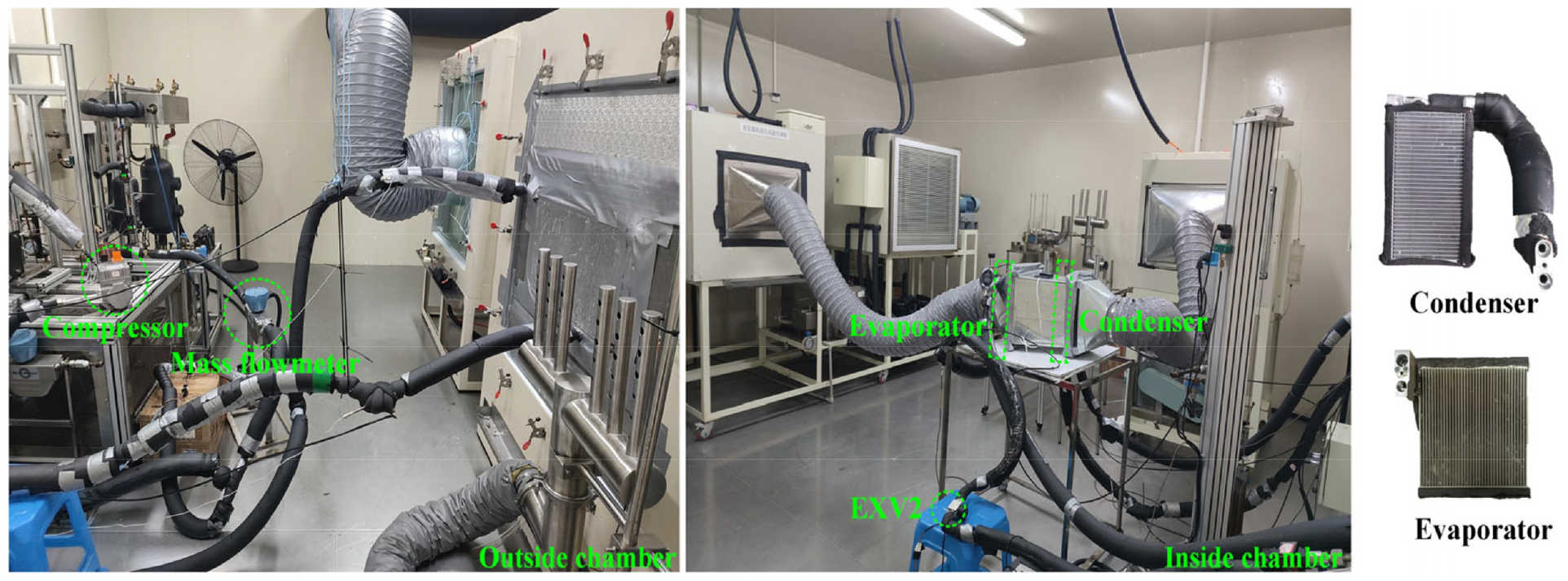
The heat transfer rate of windshield thermal conduction (Qw) is obtained from equation (3), where λw is the thermal conductivity of the windshield and δw is the thickness of the windshield.
The simplification of convective heat transfer on the inner surface of the windshield is consistent with the simplification made for convective heat transfer on the outer surface of the windshield. The convective heat transfer coefficient between the inner surface of the windshield and the air supply (hi) can be gained from equation (4). 15

Ignoring the thermal resistance of the liquid film, the heat transfer rate between the inner surface of the windshield and the air supply (Qi) is shown in equation (5).

In this study, the thermal conductivity of the windshield is 0.76 W/(m·K). The thickness of the windshield is 5 mm. The dry bulb temperature of the outdoor air assumed in this study is 0°C with a relative humidity of 40%. The 60 km/h is the assumed vehicle speed in urban areas. It is assumed that air velocity outside the windshield is the same as vehicle speed. 15 The air outlet velocity of the HVAC module is 4.5 m/s. The air outlet velocity is determined by the airflow (unit: m3/h) and the area of the air outlet. The airflow of the HVAC module is maximized (350 m3/h) during dew or fog removal. The temperature of the inner surface of the windshield is determined by the heat transfer model.
The temperature of the inner surface of the windshield should be higher than the dew point temperature (td) of the air supplied by the HVAC module to achieve rapid dew or fog removal, as shown in equation (6). The air outlet of the HVAC module is relatively hot and there is a vapor partial pressure difference with the liquid film formed on the inner surface of the windshield, which causes dew or fog formed on the windshield to evaporate quickly.

When the temperature and relative humidity of the air supplied by the HVAC module is known, it can derive the inner surface temperature of the windshield and determine whether the requirements for dew and fog removal can be met.
Experimental apparatus and procedure
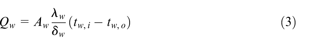
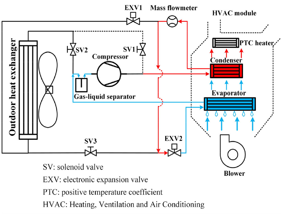
Figure 2 shows the schematic diagram of a self-designed heat pump that can be utilized for dehumidification and heating. The HVAC module of the heat pump contains two heat exchangers, named evaporator and condenser. This heat pump system can meet the demands of cooling, heating, dew, or fog removal through the opening and closing of the solenoid valves. The dehumidification and heating mode investigated in this paper is that the return air and fresh air are mixed and then passed through the evaporator to dehumidify and the condenser to heat in sequence. The system operating mode in this study is: the high temperature and high-pressure refrigerant from the compressor passes through the condenser, then throttled by the EXV2, then flows through the evaporator, and finally returns to the compressor through the gas-liquid separator. Notably, the outdoor heat exchanger is not involved in this system operation mode. In the following study, the outdoor heat exchanger can also be involved in the system cycle and the dehumidification and heating performance of the system can be studied in such system mode. Figure 3 shows the layout diagram of the experimental bench.
Schematic diagram of a heat pump for dehumidification and heating.
The layout diagram of the experimental bench.
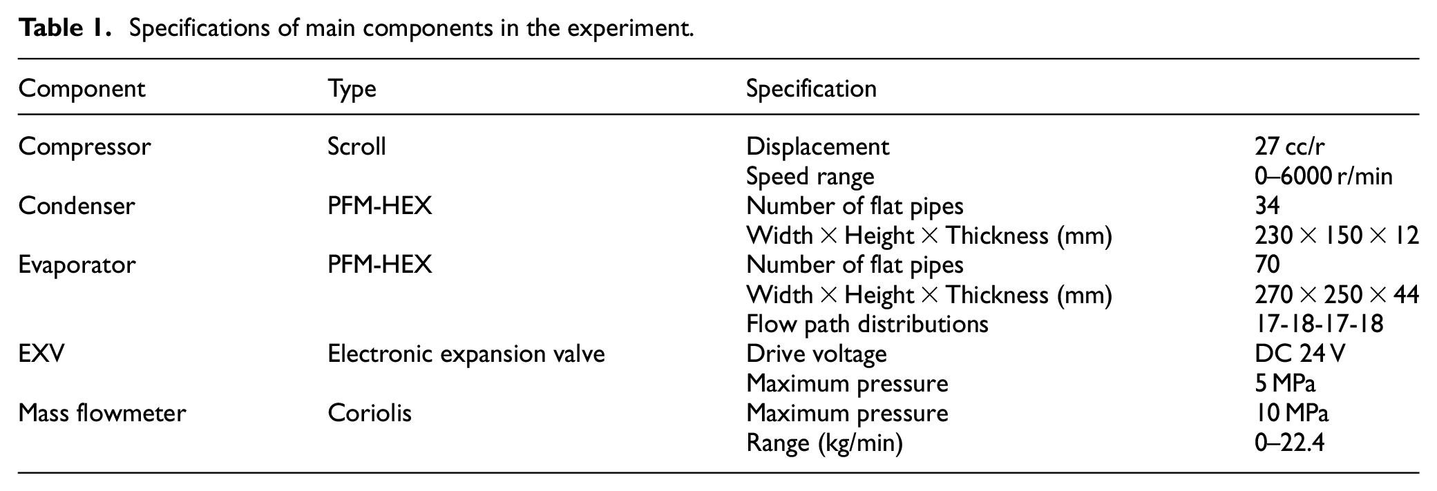
Based on the heat load demand of the cabin, components of the heat pump system were matched and selected. Table 1 lists the specifications of the main components in this experiment. The condenser is a minichannel 23 parallel-flow heat exchanger (PFM-HEX) with one flow path. The evaporator is a minichannel PFM-HEX with four paths.
Specifications of main components in the experiment.
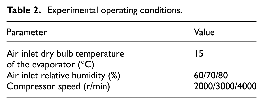
It is assumed that the dry bulb temperature is 20°C and the relative humidity is 90% for the return air in the cabin. Table 2 summarizes the experimental operating conditions. The air inlet dry bulb temperature of the evaporator was set as 15°C, and the relative humidity was 80% (RH 80%), 70% (RH 70%), and 60% (RH 60%), respectively. The fresh air ratio (ratio of fresh air mass flow to return air mass flow) was 0.52, 0.66, and 0.82, respectively. The compressor speed was set as 2000, 3000, and 4000 r/min, respectively. The dehumidification and heating performance of the heat pump system was tested under various compressor speeds and various inlet air humidities.
Experimental operating conditions.
Temperature and pressure measurement points of refrigerant were arranged in the pipes of the heat pump system, including the suction and discharge of the compressor, the inlet and outlet of the condenser, and the inlet and outlet of the evaporator. Temperature and relative humidity measurement points of air were placed in the air duct, including the evaporator outlet and condenser outlet. The system state was considered stable after the pressure fluctuation is within ±0.005 MPa. The parameters were recorded continuously for 5 min in steady-state with a data sampling interval of 10 s. The measured and calculated parameters were the averages of steady-state data.
During the pre-experiment, the refrigerant charge amount of the system and the opening of the electronic expansion valve were determined by whether thermodynamic cycles had appropriate subcoolings and superheats. After the opening of the electronic expansion valve was determined, it remained unchanged in the subsequent experiments. In the pre-experiment, the dehumidification rate obtained by the weight of droplets collected in 30 min was compared with the calculated dehumidification rate, and the results showed that the errors were within ±5%. For the condenser and evaporator, the heat transfer rates of the refrigerant side and air side were compared, and the results showed that the errors were within ±6%.
The dehumidification rate (Δmv) can be theoretically calculated by equation (7), where

The heating capacity of the condenser on the refrigerant side (Qh) is calculated as follows, where

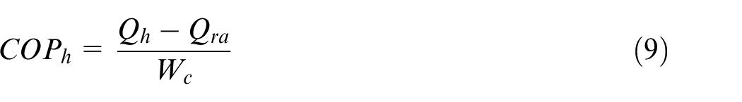
The coefficient of performance is usually understood as the ratio of the benefits to the cost. As shown in equation (9), the coefficient of performance (COPh) for heating is the ratio of the effective heating capacity (the heating capacity of the condenser minus the heat load of the return air Qra) to the power consumption of the compressor (Wc).
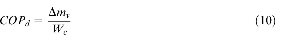
The benefit of the system dehumidification is a certain dehumidification rate, and the cost is the compressor power consumption. As shown in equation (10),22,24 the coefficient of performance for dehumidification (COPd, the unit is kg/(kW·h)) can be evaluated by the dehumidification rate per unit of energy consumption.
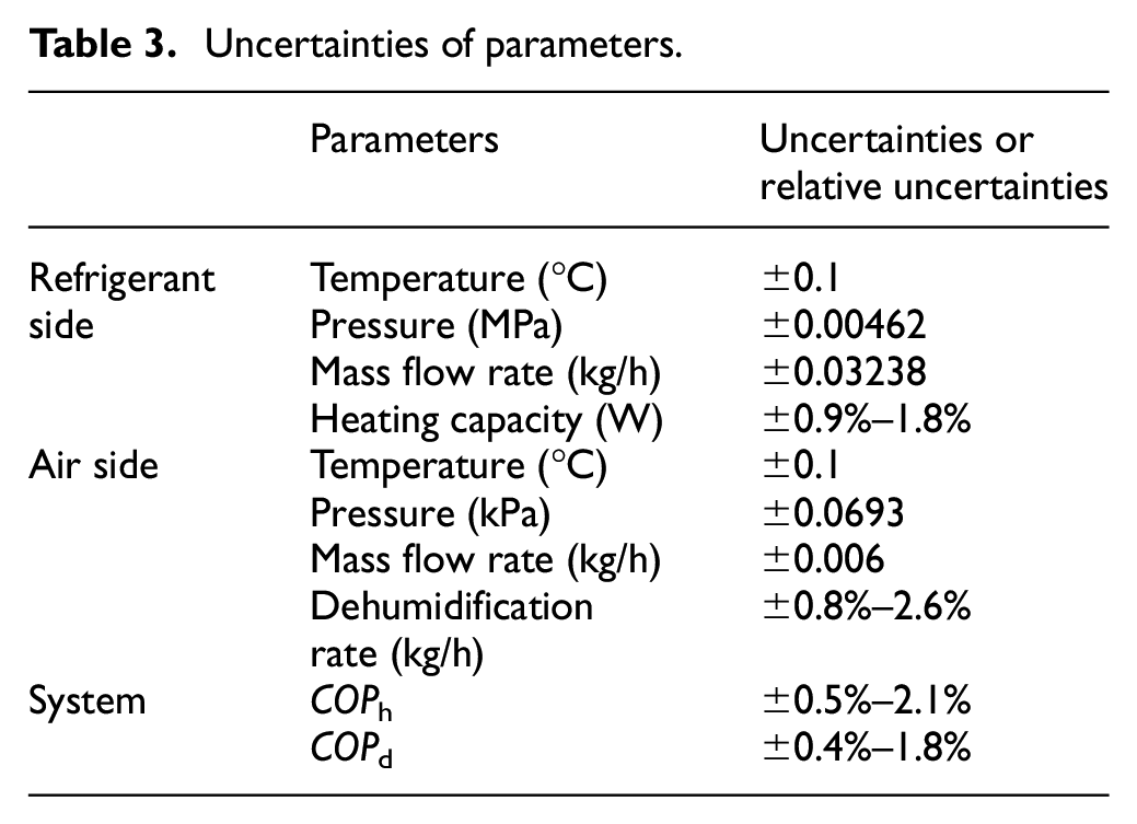
The uncertainties of the measured and calculated parameters are summarized in Table 3, in which directly measured parameters include temperatures, pressures, and mass flow rates on both the air side and the refrigerant side, and calculated parameters are the dehumidification rate, the heating capacity, and coefficient of performance.
Uncertainties of parameters.
Indoor thermal comfort evaluation
There are many methods to evaluate thermal comfort. Under steady-state conditions, the PMV (Predicted Mean Vote)-PPD (Predicted Percentage of Dissatisfied) index is the most widely used index for thermal comfort evaluation and prediction. The PMV model represents human thermal sensation as a function of six objective physical parameters, including two human parameters (human activity level and clothing thermal resistance) and four environmental parameters (air dry bulb temperature, mean radiant temperature, wind speed, and air humidity), covering all the major factors that affect human thermal sensation. In this study, it is assumed that the air supply condition of the heat pump is the final cabin environment and the average air speed in the cabin is 0.2 m/s at the steady state. The PMV and PPD are calculated using the commonly used mathematical model proposed by Fanger 25 and in the ASHRAE standard. 26 Typical human activity level (1 met, 1 met = 58.15 W/m2) and clothing thermal resistance (1 clo, 1 clo = 0.155 m2·°C/W) in winter is used in the model. Some of the black sphere temperature measurements obtained during the sample vehicle tests are used to calculate the average radiation temperature. PMVs and PPDs are calculated and analyzed based on the air supply condition of the heat pump obtained from the experiments.
Results and discussion
Assuming that the dry bulb temperature of the air supply from the HVAC module is 20–35°C, the above numerical model about ventilation conditions was used to calculate the inner surface temperature of the windshield. As shown in Figure 4(a), the inner surface temperature of the windshield is linearly related to the dry bulb temperature of the air supply (tw,i/ti = 0.47 when the ambient temperature is 0°C). According to equation (6) for judging the dew formation of the windshield, the wet bulb temperature of the air supplied by the HVAC module shall be lower than the inner surface temperature of the windshield. In addition, the internal surface temperature can be taken as the critical dew point temperature of the air outlet from the HVAC module to determine the relative humidity range of the air outlet. Thus, the suitable ventilation condition area marked in Figure 4(b) can be obtained. Figure 4(b) indicates the variation of the critical relative humidity of the air outlet with the dry bulb temperature of the air supply. The critical relative humidity of the air outlet is negatively correlated with the dry bulb temperature of the air supply. When the dry bulb temperature of the air supply is 20°C, the relative humidity of the air outlet should not exceed 50%. When the dry bulb temperature of the air supply is 35°C, the relative humidity of the air outlet should be less than 32%.
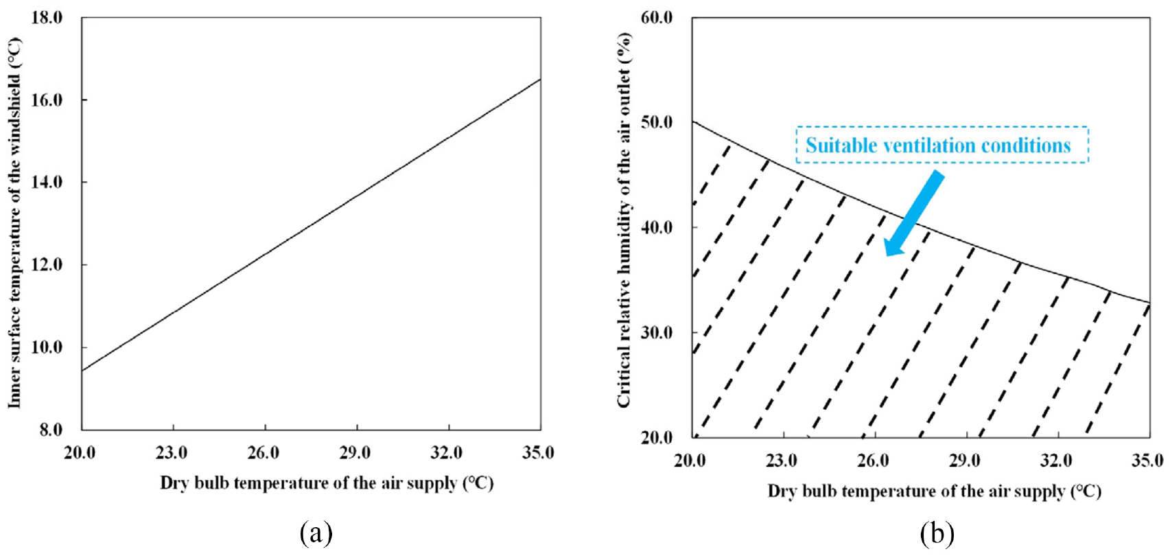
Variation of variables with the dry bulb temperature of air supply: (a) The inner surface temperature. (b) The critical relative humidity.
Firstly, the system state variation characteristics and the air supply conditions under different operating conditions were obtained from bench experiments. Then, it was determined whether the dry bulb temperature and relative humidity were located in the region of suitable ventilation conditions. In addition, the dehumidification and heating performance of the heat pump system under different operating conditions were analyzed.
As shown in Figure 5, a1/b1/c1 are pressure-enthalpy diagrams of the system state under different operating conditions of the heat pump system. At the same compressor speed, the refrigerant state varies less on the low-pressure side (evaporator inlet to compressor suction port). As can be seen in a2/b2/c2, the enthalpy differences between humid air at the inlet and the outlet of the evaporator are relatively close. The refrigerant on the low-pressure side evaporates and absorbs the heat of the humid air, and the two should be close to equal to each other. This causes the enthalpy difference of refrigerant on the low-pressure side to also vary less. In a1, the compressor discharge pressure and temperature are higher as the humidity of the air supply is higher. In b1 and c1, the inlet air humidity is 60%, and the discharge temperature decreases significantly while the pressure increases slightly. This may be caused by the variation in compressor operating conditions. When the inlet air humidity reduces, the mass flow rate of refrigerant in the system decreases, and the compressor power consumption decreases accordingly. When the inlet air humidity reduces, superheat of the compressor suction decreases as well. As can be seen in a2/b2/c2, humid air at the outlet of the evaporator is relative close to 100% relative humidity. The significant reduction in humidity ratio means that the heat pump system has an excellent dehumidification capability. Next, the ventilation conditions at the outlet of the condenser are further analyzed.
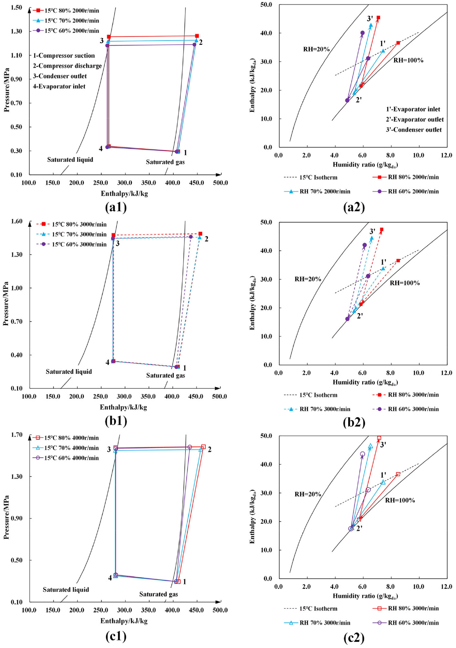
Pressure-enthalpy and enthalpy-humidity diagrams at different operating conditions (a1/b1/c1-Pressure-enthalpy diagrams of refrigerant side, a2/b2/c2- Enthalpy-humidity diagrams of air side).
Figure 6 shows the air outlet conditions of the HVAC module under different operating conditions. As the inlet air humidity reduces, dry bulb temperature and relative humidity of the air outlet are also lower at the same compressor speed. When the inlet air humidity is kept constant, the dry bulb temperature of the air outlet increases with an increase in the compressor speed, while the relative humidity of the air outlet decreases with an increase in the compressor speed.
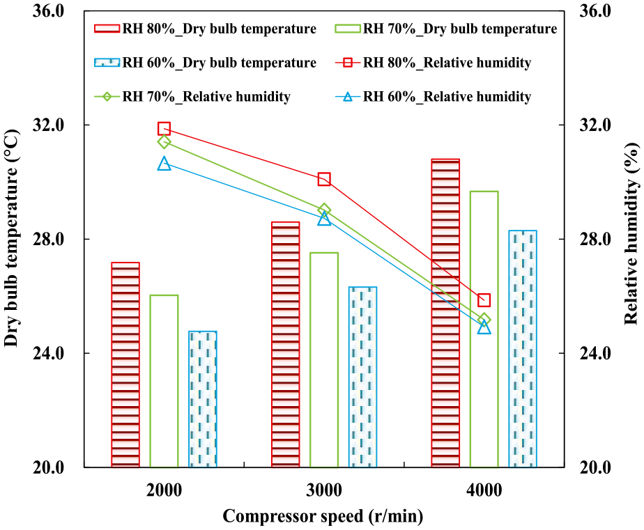
Air outlet conditions under various operating conditions.
Figure 7 compares the dew point temperature of the air outlet with the inner surface temperature of the windshield. The bar graph shows the dew point temperature of the air outlet and the inner surface temperature of the windshield for a certain compressor speed and inlet air humidity. At the same compressor speed, the difference between the dew point temperature of the air outlet and the inner surface temperature of the windshield is greater when the inlet air humidity is lower. A larger temperature difference represents a larger vapor partial pressure difference, that is, the dew or fog evaporates faster. Although the dry bulb temperature of the air outlet decreases as the inlet air humidity reduces, there is still effective dew or mist removal. At the same inlet air humidity, the difference between the dew point temperature of the air outlet and the inner surface temperature of the windshield increases with an increase in compressor speed. As the compressor speed increases, the dew or fog removal will be better.
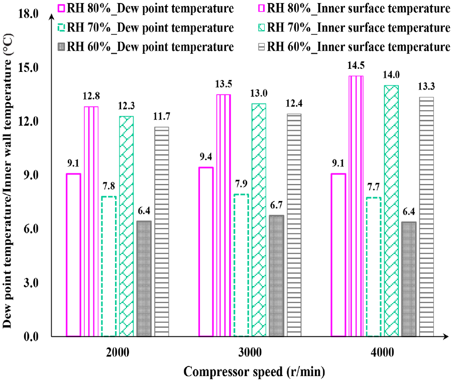
Comparison between dew point temperature of air outlet and the inner wall temperature of the windshield.
Figure 8 illustrates the variation in dehumidification rate under different operating conditions. At the same compressor speed, the dehumidification rate decreases as the inlet air humidity decrease. At this time, the evaporation temperature of the heat pump system varies little, which means that vapor partial pressure corresponding to the evaporator surface temperature fluctuates little. As the inlet air humidity is higher, the difference between the vapor partial pressure of the air supply and the vapor partial pressure corresponding to the evaporator surface temperature is larger, which means the dehumidification rate is higher. When the inlet air humidity is maintained constant, the dehumidification rate increases slightly with an increase in compressor speed. The variation in compressor speed has a slight effect on the evaporation temperature but results in a slight increase in mass flow rate.
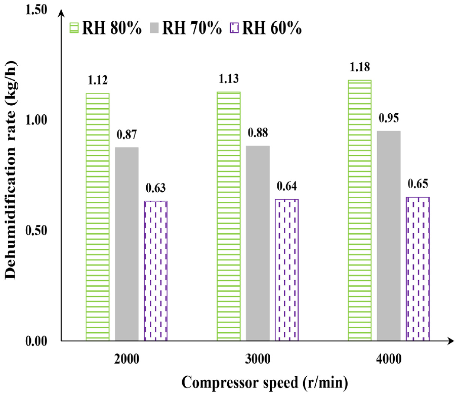
Variations of dehumidification rate under different operating conditions.
Figure 9 presents the variation of the effective heating capacity under different operating conditions. When the compressor speed is constant, the effective heating capacity increases as the inlet air humidity decreases. At this time, the heating capacity of the condenser does not vary much while the heating load of return air decreases significantly, which makes the effective heating capacity increase. When the inlet air humidity is constant, effective heating capacity increases with an increase in the compressor speed. In this case, the heating capacity of the condenser increases significantly, while the heating load of the return air varies less.
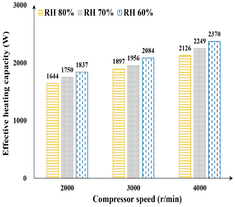
Effective heating capacity under different operating conditions.
At the same compressor speed, the dehumidification rate decreases with a decrease in the inlet air humidity. The heat transfer and mass transfer of humid air have the opposite trend. In the process of dehumidification, part of the vapor condenses on the evaporator surface. After a period of stable operation of the system, the evaporator surface may form a liquid film to suppress heat transfer. A higher dehumidification rate results in a thicker liquid film thickness, which reduces the heat transfer rate.
Figure 10 shows the variations in coefficient of performance (COPh and COPd) under different operating conditions. At the same compressor speed, the compressor power does not vary much. The effective heating capacity increases with the decrease of the inlet air humidity, which causes COPh to increase with the decrease of the inlet air humidity. The dehumidification rate decreases as the inlet air humidity decreases, which results in that COPd also decreases as the inlet air humidity decreases. At the same inlet air humidity, an increase in compressor speed results in an increase in effective heating capacity and power consumption. The increase in compressor power is more obvious than the increase in effective heating capacity, which causes COPh to decrease with an increase in the compressor speed. Similarly, at the same inlet air humidity, the increase of compressor power at increased compressor speed is more significant than the increase of dehumidification rate, which leads to a decrease of COPd with increased compressor speed. At the same compressor speed, COPh and COPd show an opposite trend as the inlet air humidity decreases. The reduction of inlet air humidity is more beneficial for heat transfer rather than mass transfer.
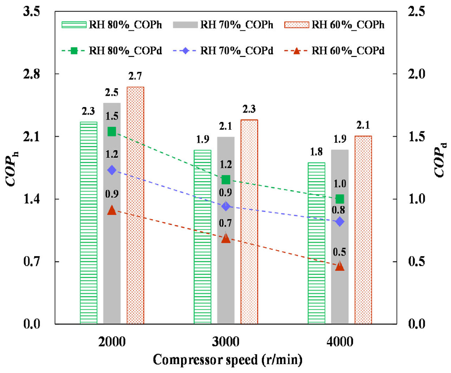
Variation of coefficients of performance under different operating conditions.
Figure 11 presents PMVs and PPDs calculated by the air supply conditions of the heat pump. Under the same inlet air humidity conditions, PMV and PPD increase with the increasing compressor speed. At the same compressor speed, PMV and PPD tend to increase with the higher inlet air humidity. At the compressor speed of 2000 r/min and inlet air humidity of 60% and 70%, the PMVs and PPDs meet the thermal comfort requirements of ASHRAE Standard 55-2017 (−0.5 ≤ PMV ≤ +0.5%,and PPD ≤ 10%). When dew and fog removal is required, and the thermal comfort of the cabin is ensured, the heat pump system should run at a lower compressor speed and inlet air humidity.
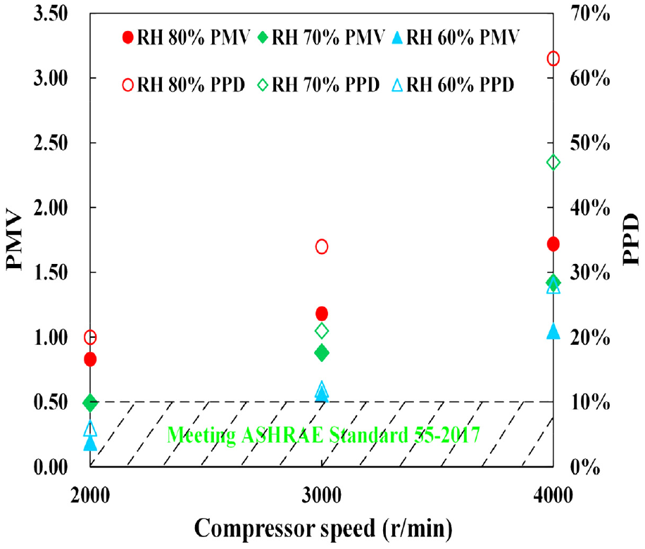
PMVs and PPDs calculated by the air supply conditions of the heat pump.
Concluding remarks
The dehumidification and heating characteristics of a new-designed EV’s heat pump system was studied in this paper, meanwhile, the ventilation conditions of the HVAC module for dew and fog removal requirements were determined. Several attained meaningful conclusions are as follows:
1) The windshield’s inner surface temperature has a positive linear relationship with the air-supply’s dry bulb temperature. However, the air-outlet’s critical relative humidity is negatively correlated with the air-supply’s dry bulb temperature on the premise of dew and fog removal.
2) At the same compressor speed, the dew or fog removal is more effective when the inlet air humidity is lower. At the same inlet air humidity, however, the compressor speed is higher for better dew or fog removal.
3) When the compressor speed is held constant, the decreasing inlet air humidity decreases the dehumidification rate and increases the heating capacity, respectively. Under the unchanged inlet air humidity, the increasing compressor speed effectively increases the heating capacity; however, the dehumidification rate does not vary much.
4) At the same compressor speed, the coefficient of performance for heating increases but the coefficient of performance for dehumidification decreases with the decrease of inlet air humidity. At the same inlet air humidity, the coefficient of performance for heating and coefficient of performance for dehumidification decrease with an increase in the compressor speed.
5) With the heat pump system operating at the lower compressor speed and the lower inlet air humidity for the evaporator, the demand for dew or mist removal of the windshield is met and the thermal comfort of the cabin is ensured.
The study in this paper only focuses on the dehumidification and heating characteristics of the heat pump system. The dehumidification and heat transfer characteristics of the heat exchanger itself need to be further investigated. The heat and mass transfer mechanism and modeling of the heat exchanger under wet conditions can also be further explored. In addition, the system operation mode of dehumidification and heating can also utilize the outdoor heat exchanger to absorb the outdoor heat to improve the system energy efficiency and ensure the dehumidification effect. Further investigation is needed for such modes.
Footnotes
Appendix
Declaration of conflicting interests
The author(s) declared no potential conflicts of interest with respect to the research, authorship, and/or publication of this article.
Funding
The author(s) disclosed receipt of the following financial support for the research, authorship, and/or publication of this article: This work was supported by China Postdoctoral Science Foundation (No. 2021M702191) and National Nature Science Foundation of China (No. 5220061362).