
Abstract
A variable geometry inlet configuration can improve the off-design aerodynamic performance of a turbocharger compressor by actively modulating the internal flow field. As the core part of the configuration, the variable geometry orifice is arranged in front of the compressor inducer. Its novelty is to actively regulate the compressor inlet flow area at an off-design point without causing significant impact at the design point. In this paper, the effects of the orifice on compressor performance and internal flow field are investigated using experiments and numerical simulations. The experimental and the numerical results confirm the variable inlet configuration to be a promising method for extending the compressor operation range. The DES calculations reveal incidence angle reduction at inducer inlet, shock wave migration to a lower radius from blade tip, formation of the aft-loaded impeller, reduced difference between jet and wake flows at impeller exit, and turbulent flow enhancement in the diffuser. Based on understanding the orifice’s effects on the centrifugal compressor, a design suggestion is proposed for the variable geometry compressor of this sort.
Keywords
Introduction
The centrifugal compressor has wide applications in a turbocharged engine as the core compression component of a turbocharger. Its aerodynamic performance and stable operating range are of importance to improve the engine performance and safety. The centrifugal compressor design often has a trade-off between the design and the off-design points to have good global performance, including efficiency optimization and stall/surge margin extension. The reason for the trade-off is that a designer is hard to improve compressor performance significantly at off-design points without deteriorating efficiency at the design point. Usually, at the off-design points, the internal flow organization of the compressor is not as optimum as at the design point. An active flow controller may improve the internal flow organization at the off-design points; meanwhile, by actively varying geometry, it does not have unwanted effects on the compressor flow field at the design point. As stated by Gallar et al., 1 compressor variable geometry as one of the stability aides can raise surge line for the provision of an adequate surge margin. It is necessary, therefore, to develop variable geometry compressors.
Academy researchers and engineers have made many efforts to develop variable geometry centrifugal compressors. For instance, Sun et al.2,3 proposed a switchable dual-slot casing treatment to make a centrifugal compressor have an increased performance map width. Subsequently, Hu et al. 4 and Dehner et al. 5 confirmed the effectiveness of the variable geometry casing treatment. Another approach to control the internal flow is to change the diffuser vane geometry. 6 The vaned diffuser has the variable geometry function, thus improving the matching between the setting angle of diffuser vanes and the flow angle at the impeller exit.7,8 Besides, the variable inlet guide vane (IGV) has come to concern right from the development of centrifugal compressors and has been widely used in industrial compressors. It can change the incidence angle at the impeller inlet, thus improving off-design performance, but it always causes a performance penalty at the design point because of the boundary layer and rotor-stator interaction.
In recent years, a novel inlet configuration has been confirmed to have potential benefits in the aerodynamic performance of a centrifugal compressor. 9 As one of the typical designs, the variable geometry configuration is at the centrifugal compressor inlet and, by actively controlling the flow area, can increase centrifugal compressor performance map width and improve efficiency at some operating points. 10 The physical mechanism is entirely different from those adopted by variable geometry casing treatment and the variable geometry diffuser vanes. The author’s previous work 11 confirmed the effectiveness of variable geometry configuration in improving compressor off-design performance and extending stability margin. The subsequent research proposed a multiple-stage control concept for maximizing the improvement. 12 Compared with other variable geometry approaches, the variable geometry orifice can be withdrawn from the compressor inlet when it is not needed and thus does not cause a significant compressor efficiency penalty. So far, the effect of the orifice on the compressor flow field, including incidence angle at inducer inlet, shock wave standing on the blade surface, and jet/wake flow at impeller exit, has not been fully known. A deep understanding of the compressor flow variations in response to the orifice is believed to help develop advanced variable geometry compressors.
This paper provides a deep insight into the effect of variable geometry inlet configuration on a centrifugal compressor. The compressor aerodynamic performance is obtained by using the physical experiment and steady simulations. The internal flow analysis is mainly based on the time-dependent detached eddy simulation (DES) results. According to the experimental and numerical results, a design suggestion is proposed for the variable geometry compressor of this sort.
Investigated model
The investigated model is a centrifugal compressor. The compressor has an inlet duct, an impeller, a vaneless diffuser, a volute, and an outlet pipe. The impeller has 11 blades, and its detailed geometry parameters are listed in Table 1.
Main geometry parameters of the impeller.
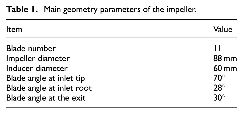
Figure 1 depicts the variable geometry configuration at the compressor inlet. As Herbst and Eilts 13 reported, the design of a freely adjustable mechanism to adapt the compressor trim at the operation point is one of the investigation concerns. We depict a detailed geometry design that can achieve a freely flexible configuration, as shown in Figure 2. As the core part of the configuration, the variable geometry orifice can change the diameter of its inner rim and then actively regulate the flow area by inserting it into the compressor inlet duct. As a result, the active control of the aerodynamic performance can be achieved.
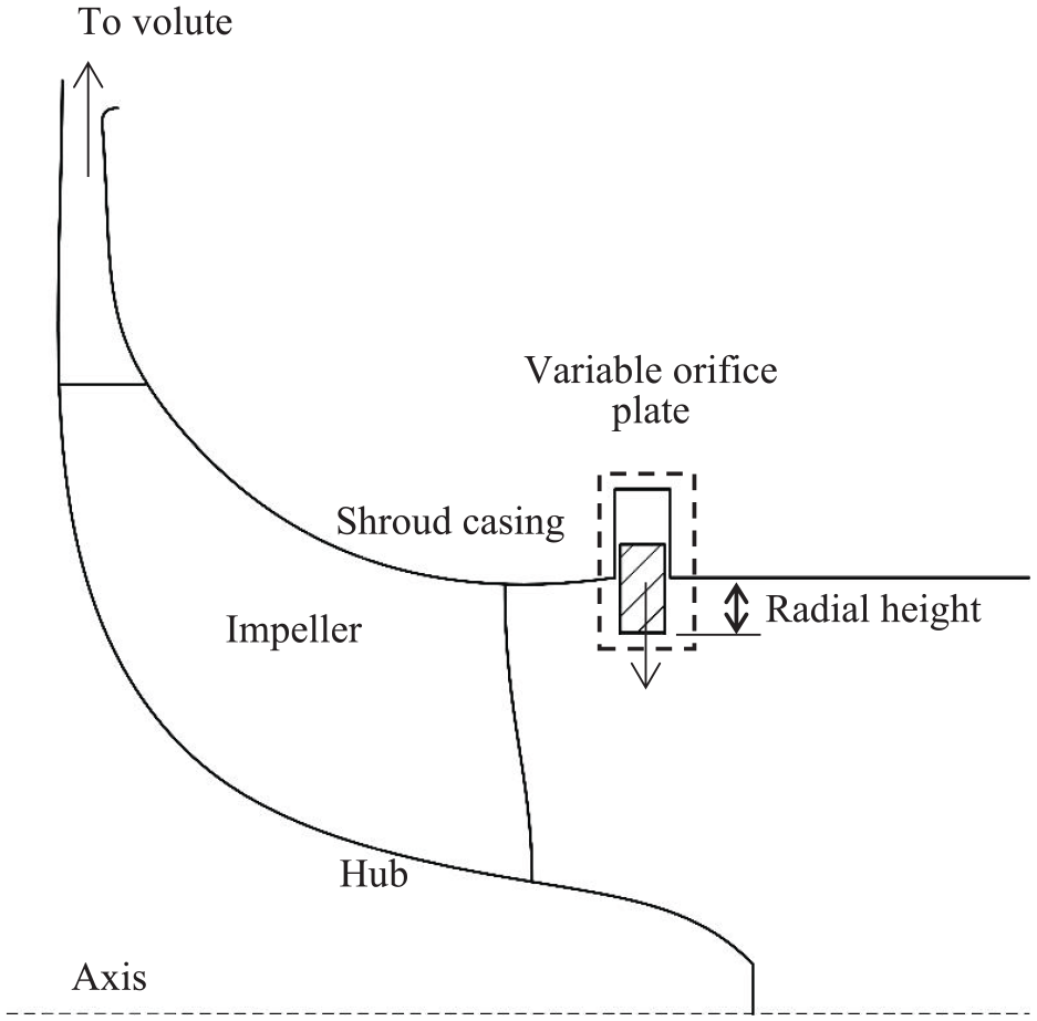
Illustration of the compressor with the variable orifice plate formed by moving vanes at the compressor inlet, Case 1.
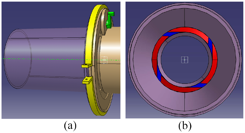
Variable geometry configuration for flow area reduction: (a) variable geometry structure and (b) the left view of the reduced flow area.
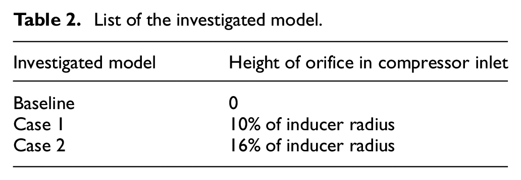
This paper investigates three models, as listed in Table 2. The first one is the baseline compressor, in which the inner rim of the orifice has the same diameter as the compressor inlet duct. Consequentially, the orifice does not affect the compressor. The second model is the centrifugal compressor with the orifice in its inlet duct and is referred to as Case1. The orifice has a radial height of about 10% of the inducer radius, located upstream of the impeller leading edge by about 47% of the inducer radius. The third model is the centrifugal compressor with a 16% inducer radius orifice in its inlet duct, called Case 2. The orifice is located at the same location as that in Case 1.
List of the investigated model.
Experimental setup
Experiments were conducted only on two cases, Baseline and Case 2. They were based on a turbocharger flow bench and aimed to test the effects that the orifice plate has on the compressor aerodynamic performance, thus validating, in part, the numerical simulations. Figure 3 shows the turbocharger flow bench layout. The compressor draws air from the atmosphere environment through a straight pipe. The high-pressure air from the compressor exit was discharged into the atmosphere through pipelines. A radial inflow turbine drove the compressor through a common shaft. The turbine was driven by high-pressure air from a set of screw compressors. The compressor performance map could be tested by actively controlling the valves arranged on the pipelines. It was not until the entire system got into the ready state that all experimental data were recorded.
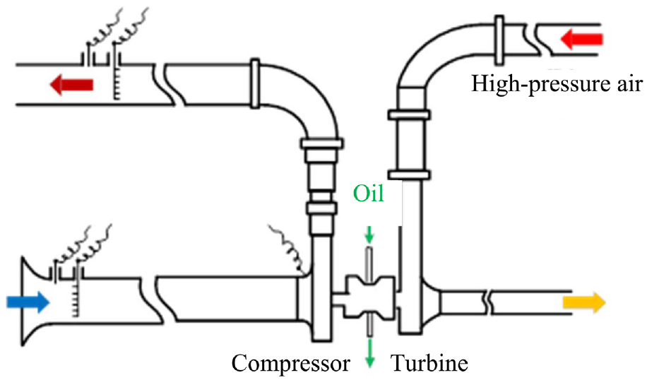
Experimental set arrangement.
A double folium curve flow meter was arranged at the end of the inlet pipe to obtain the air mass flow rate. A few sensors were arranged on the inlet and outlet pipes to measure the total pressure and total temperature. Uncertainty of the pressure sensor is 0.1%. The turbocharger speed sensor was mounted in a hole bored into the compressor housing and directly sensed each impeller blade, thus measuring the compressor rotational speed. The oil was pumped into and out of the bearing system. It can lubricate bearings while also carrying away the heat from the turbine.
Numerical scheme
The numerical scheme used in this paper includes the time-independent (steady) and time-dependent (unsteady) simulations. The steady simulations are performed on the whole compressor stage model and the single-passage impeller model to predict aerodynamic performance. The detached eddy simulation (DES) as the unsteady simulation is carried out only on the single-passage impeller model to simulate the internal flow of the compressor. All calculations are solved by the commercial software, NUMECA Fine/Turbo with the version of 11.1.
Computational mesh
Figure 4 shows the structural mesh of the whole compressor stage. The meshes in the impeller and the inlet duct were created automatically with the HO topology pattern. Specifically, a O-type block was used around the blade to simulate the flow inside the boundary layer, and four H-type blocks were used inside the channel to connect with the O-type block. A H-type block surrounded by a O-type block was used in the blade tip clearance, with 17 grid points in the span-wise direction. The butterfly topology pattern is applied in the volute and outlet pipe grids because of its advantage in meshing the complicated geometry. The gap behind the impeller is neglected. Twenty million grid points were used to mesh the complete model.
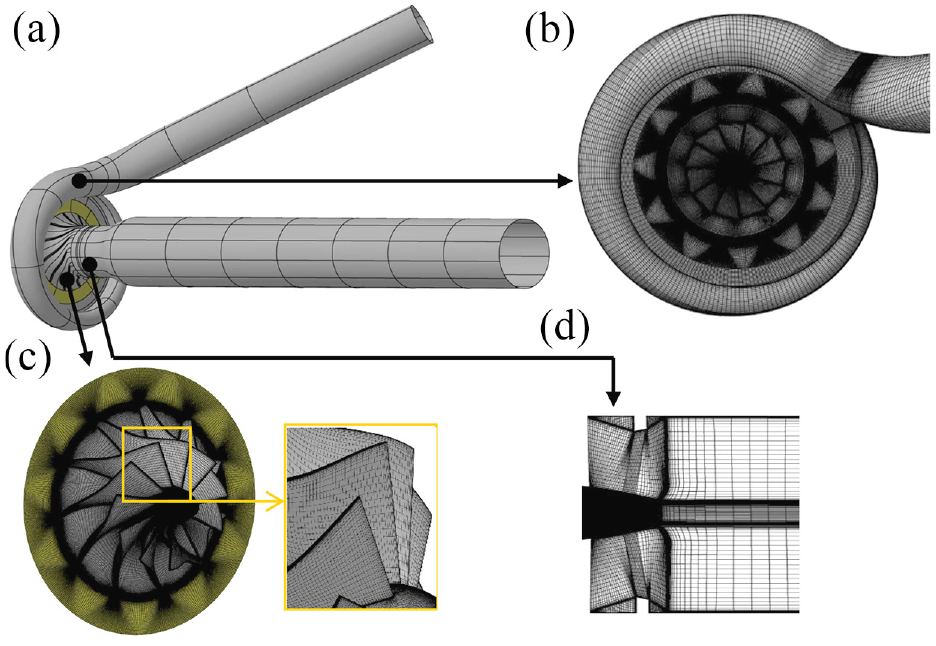
The whole compressor stage model and mesh for the steady simulations: (a) the investigated compressor, (b) the volute mesh, (c) the impeller and diffuser, and (d) the inlet duct with orifice.
The mesh has an averaged y+ value of 1.41. The maximum value is around 7, within the range suggested by the NUMECA manual. The cell size sensitivity is analyzed by performing steady simulations and comparing compressor performance. Figure 5 shows the compression and proves that the current computational mesh meets the investigation requirement. The maximum aspect ratio of cells is less than 900. Some researchers6,14,15 reported that for a centrifugal compressor of this sort, about 7 million grid points are sufficient for a RANS simulation, thus supporting the effectiveness of the 20 million.
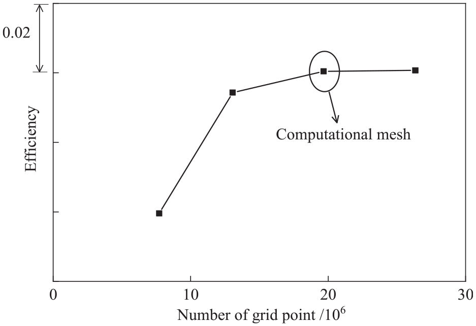
Sensitivity analysis of the grid numbers with predicted results based on the whole compressor stage model.
Figure 6 shows the flow domain of the single passage model. The numbers of grid points around the impeller blade are marked. In both the pitch-wise and the span-wise directions, 209 points were used. Along the stream-wise direction, 493 points were specified. The inlet duct and the vaneless diffuser were simulated to eliminate the effects of boundary conditions on the impeller flow field. The total number of grid points for the single passage model is over 26 million. A literature survey16,17 shows that the highly accurate simulation is often conducted on a single passage model and the grid nodes usually range from 20 million to 40 million for a single passage.
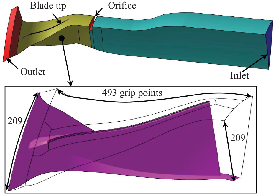
The single passage model and illustration of grid points for the DES simulations.
Numerical scheme
The Navier-Stokes (N-S) equations were solved by the density-based solver embedded in the Fine/Turbo package based on a cell-centered control volume approach. The perfect gas law was used to describe the working fluid, air. The discretization in space was based on a cell-centered control volume approach. In the turbulent N-S equations, the viscous fluxes were determined in a purely central way. The Gauss’ theorem is used to evaluate the gradients on the cell faces. The inviscid fluxes were centered-based numerical fluxes. The Jameson type dissipation with second and fourth order derivatives of the conservative variables were adopted. The explicit four-stage Runge-Kutta scheme was used with the local time-stepping for the time discretization. The CFL number of three is specified. The second-order schemes were used. The calculation employs the implicit residual smoothing method to speed up the convergence. The multi-grid strategy was employed as another method for efficiency and fast convergence.
For the steady simulations, the Reynolds Averaged Navier-Stokes (RANS) equations are solved, which are derived by averaging the viscous conservation laws over a certain time interval. The RANS computation requires treating the Reynolds stress tensor and turbulent heat diffusion term. The one equation turbulence model, the Spalart-Allmaras (S-A) model, was employed because it could treat complex flows and the relatively lower additional CPU and memory usage. 18 The compressor stage mesh has a rotor-stator interface in the middle of the vaneless diffuser. The part upstream of the rotor-stator interface was solved in the rotating frame of reference. In contrast, the downstream part was simulated in the stationary frame. To transfer all fluid information between the two parts, the frozen rotor technique was employed at the interface. As reported in Sun et al., 19 the frozen rotor method has an advantage in simulating the non-axisymmetric distribution in a compressor having volute.
For the unsteady simulation, the solver, the density-based time accurate solver, was employed to solve the time-dependent N-S equations. The dual time-stepping approach was used, which added pseudo-time to the time-dependent N-S equations. A steady-state problem was solved in the added pseudo time. The treatment of turbulent flow was based on the DES model. The model was first proposed by Spalart and Shur. 20 Compared to the standard S-A turbulent model, the turbulent length scale in DES, dW, is replaced by the DES length scale, lDES.

Where Δ is a measure of the width of the filter related to the calculation and calculated by the following equation.
Δ = max(Δx,Δy,Δz)
The variable, CDES, is a calibration constant and, according to the suggestion stated in the manual, is specified to be 0.65.
The density-based time accurate solver used the dual time stepping approach proposed by Jameson. 21 The time step is specified to be 1e-7s (about 0.0618 degrees for the impeller rotation). The unsteady calculation (DES) was carried out only on the single passage meshes with periodic boundary conditions. There is no rotor/stator interface. Given that the inlet orifice has symmetrical geometry, simplifying the domain is a promising method to investigate the effects of the orifice on the impeller and diffuser.
Boundary conditions
The ambient pressure and temperature were specified at the computational domain inlet with a turbulent viscosity. The orientation of the velocity was normal to the inlet surface. With the requirement of S-A turbulence model, the turbulent viscosity was imposed. At the outlet boundary, the static pressure was specified as the back pressure. Other dependent variables were obtained from the interior field through a zero-order extrapolation. More detailed information about the solution can be found in the NUMECA manual.
In all simulations, the adiabatic assumption was employed on walls. The velocity vector is assumed to vanish on the wall. The wall temperature was obtained using a similar equation, like the pressure on a wall. Depending on the type of perfect gas, the density can be calculated.
Performance validation
Figure 7 compares the numerically predicted compressor aerodynamic performance with the test result. The compressor mass flow rate is normalized by dividing the maximum flow rate at 100% speed. Figure 7(a) depicts the compressor pressure ratios against the mass flow rates. The following equation calculates the pressure ratio.
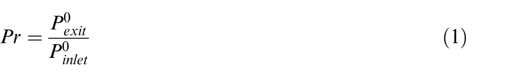
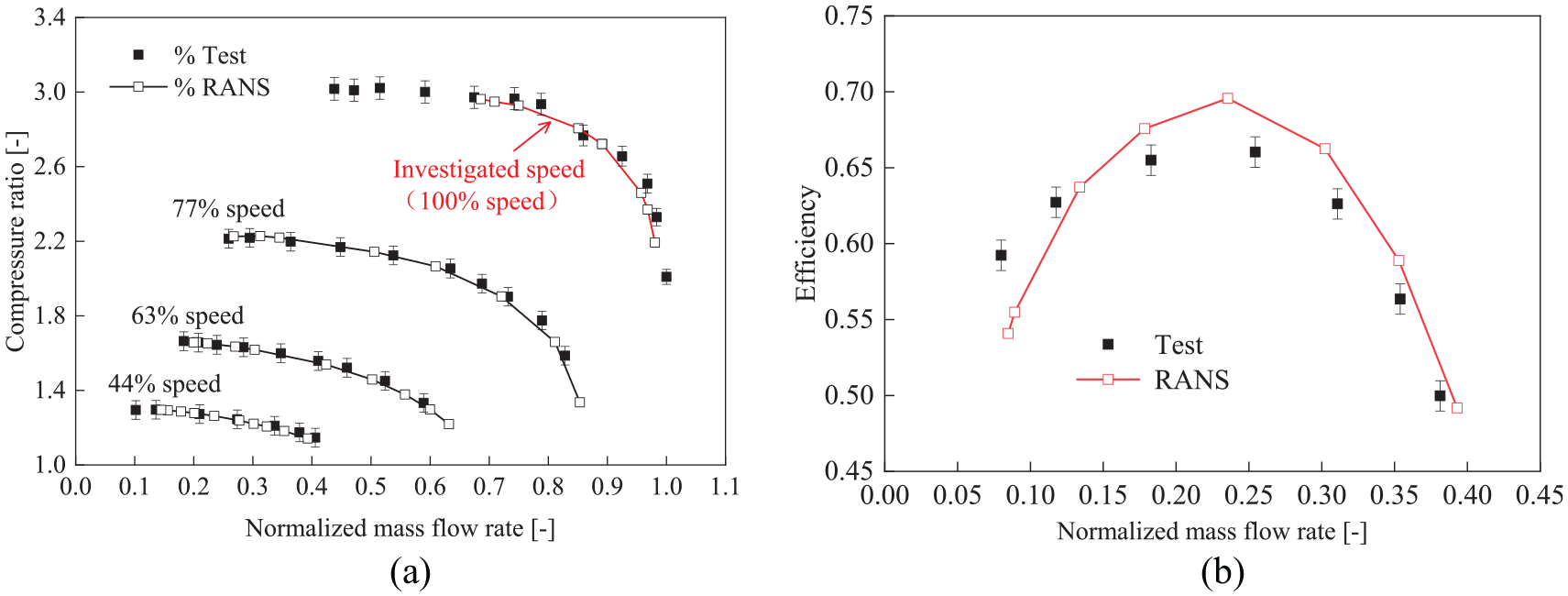
Comparison of numerically predicted compressor performance against test data (the steady RANS results of the whole compressor stage model): (a) pressure ratio versus mass flow rate and (b) efficiency versus mass flow rate at 44% speed.
Where Pr stands for the compressor pressure ratio;
The comparison reveals a good agreement between the numerical and experimental results. The investigated speed in this paper is marked in Figure 7(a). At the investigated speed, the DES simulations were carried out.
Figure 7(b) compares the isentropic compressor efficiency between the numerical and experimental data. The following equation calculates the compressor efficiency.
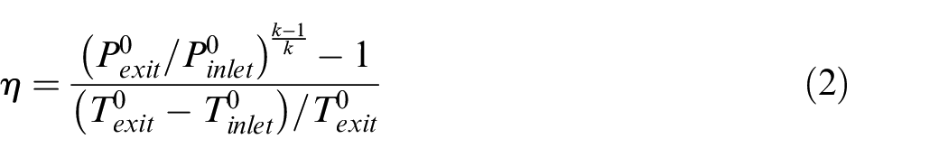
Where
Around the peak efficiency operation point, the RANS simulations on the whole compressor stage model over predict the compressor efficiency while predicting lower efficiencies at the near surge margin. Four reasons may contribute to those discrepancies. The first one is the adiabatic wall assumptions used in the numerical computation but not the test model. The second is the complicated flow occurrence in the compressor. It is still challenging for the current steady RANS scheme to accurately simulate the complex flows because the RANS method neglects all unsteady interactions. The third is the heat transfer from the turbine to the compressor. In a turbocharger flow bench, the turbine usually has a higher temperature than the compressor. Although the oil can carry away a part of the heat from the turbine, the heat transfer from the turbine to the compressor still occurs and affects the compressor. The last one may be geometry simplification. The gap is neglected between the impeller and the backplate in the numerical model.
Even though a few discrepancies are identified in the compressor isentropic efficiency, the agreement between the experimental and the numerical results can be considered globally satisfactory, thus giving confidence to the calculation scheme.
Additional validation
The validation above is entirely based on the compressor performance and needs more detailed validations to prove the reliable numerical scheme. As an additional verification, the same simulation method is performed on the centrifugal compressor that our team tested at the Beijing Institute of Technology. The two compressors have a similar Reynolds number, machine Mach number, and the same working fluid and inlet conditions, as shown in Figure 8. Table 3 lists their dynamic similarity parameters. The same range of parameters meets the requirement of dynamic similarity, thus supporting the current validation effectively.
Comparison of two compressors.
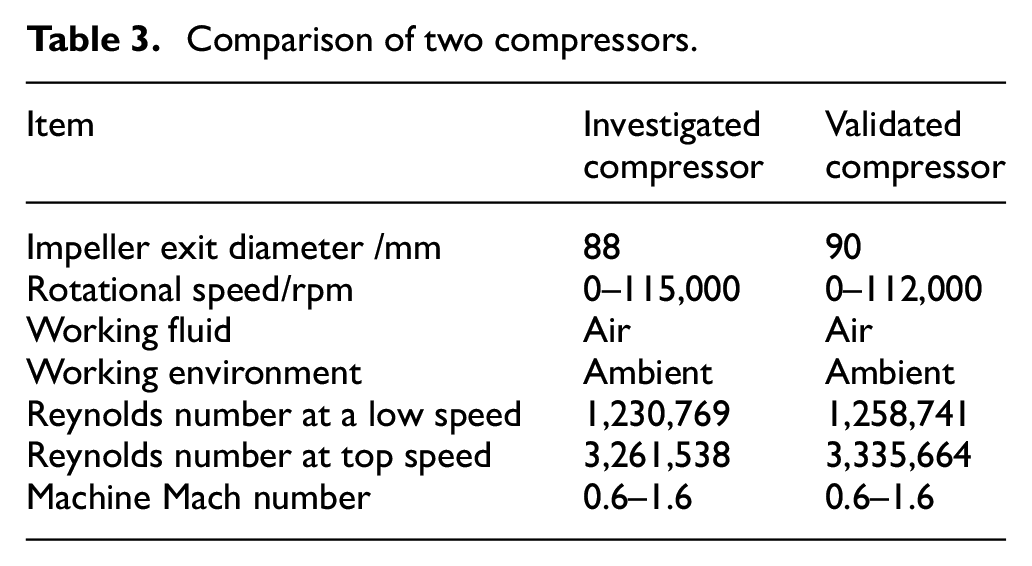
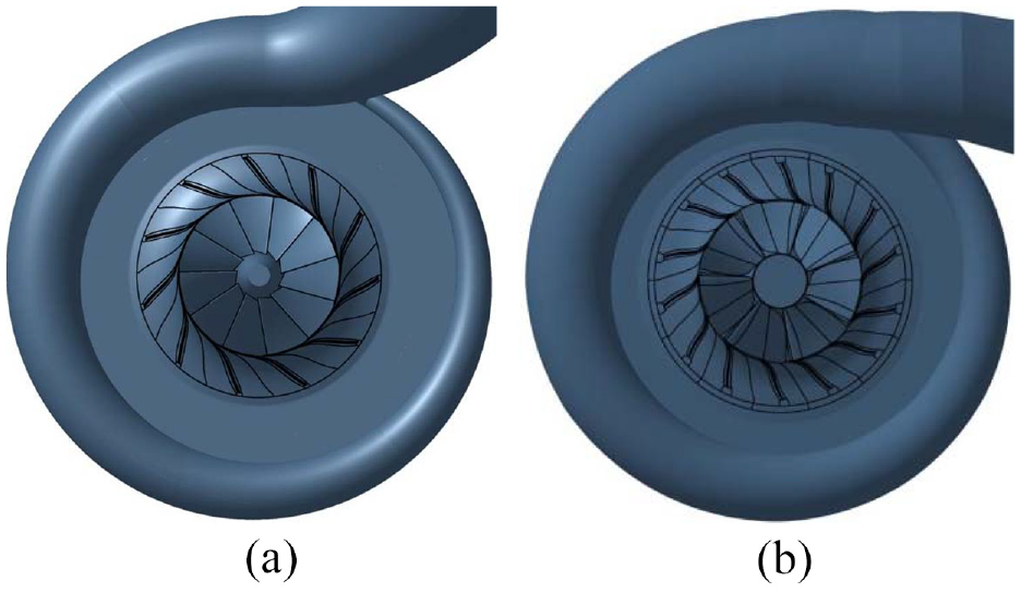
Illustration of centrifugal compressor models: (a) the current investigated compressor and (b) the tested model as supplementary validation.
Figure 9 presents the comparison between the numerical results and the test data. Figure 9(a) and (b) depict the compressor performance data. Like the comparison shown in Figure 7, the speed-lines have a good agreement, and it proves the capacity of the current simulation method in predicting the compressor performance. Figure 9(c) and (d) compare the static pressure in the compressor flow field. Six points were measured at the compressor inlet, and 12 monitoring points were arranged on the shroud casing from the impeller inlet to exit. More information regarding the experiments can refer to,22,23 and we do not repeat the introduction here. The comparison reveals consistent static pressure distributions in the compressor flow field, thus further validating the numerical scheme.
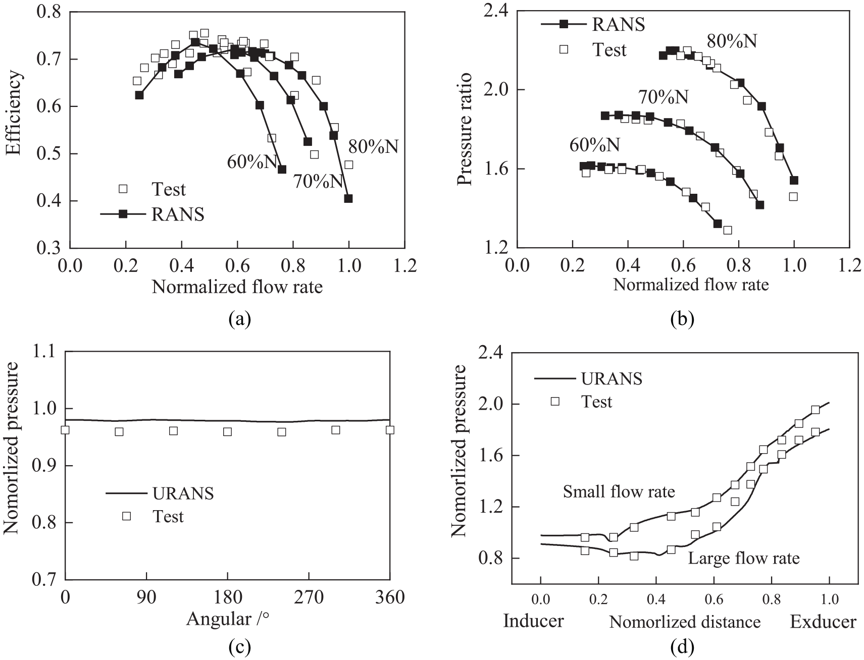
Validation of numerical scheme on a centrifugal compressor we tested before: (a) compressor efficiency, (b) compressor pressure ratio, (c) static pressure around compressor inlet duct, and (d) static pressure on shroud casing.
Results and analysis
This section discusses the effects of the inlet orifice on the compressor performance according to steady numerical and test results and the internal flow behaviors based on the DES results. The DES simulations were carried out at the investigated speed marked in Figure 7(a), where the relative Mach number near the blade inlet tip is about 1.4.
Comparison of the experimental and numerical results
Figure 10 shows the pressure ratios based on the whole compressor and the single-passage models. The pressure ratio is expressed as the compressor mass flow rate function at the investigated rotation speed. In Figure 10(a), the numerically predicted pressure ratios agree well with the experimental results for the baseline compressor and Case 2. The performance of Case 1 is just in the middle of two other cases. This phenomenon is consistent with the theoretical result in Zhao et al. 10 that the orifice height is proportional to the extension of the compressor operating range and the finding in Grigoriadis et al. 24 that the surge line is shifted toward a lower mass flow rate.
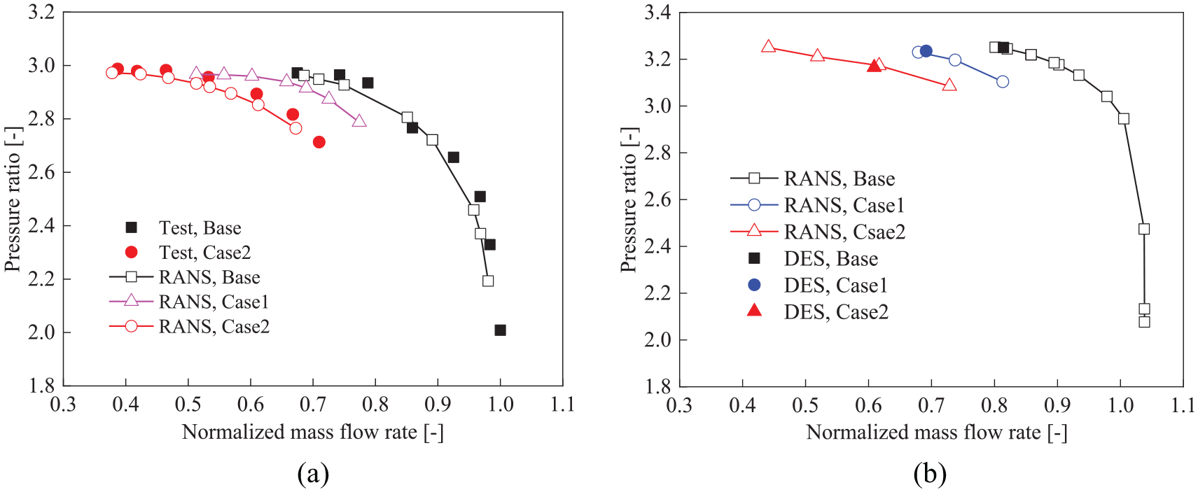
Comparison of compressor performance between experimental data and RANS results (the speed is marked in Figure 7(a)): (a) comparison of RANS and test results, whole compressor stage model and (b) pressure ratio comparison of RANS and DES results, the single passage model.
The same numerical scheme is used to predict the aerodynamic performance of the single-passage model, as shown in Figure 10(b). The speed lines for the three models have a similar distribution as in Figure 10(a). The compressor speed-line moves to a lower mass flow rate with the orifice height increase. Consequentially, the movements of speed lines, shown in both Figure 10(a) and (b), consistently confirm the effectiveness of a variable geometry orifice in improving the stable operation range of the centrifugal compressor.
Meanwhile, the similar distributions of speed lines in both Figure 10(a) and (b) also provide confidence in the alternation of the investigation model from the whole compressor stage to the single-passage model. The DES calculations essentially require the cell size to be smaller than the turbulence scale and now are a significant challenge in computer resources for the simulation of the whole compressor stage. Therefore, this paper performed the DES calculations only on the single-passage mesh with decreased cell size.
The operating points at which the DES calculations were carried out are marked in Figure 10(b) for the baseline, Case 1, and Case 2, respectively. They have the same rotational speed but different mass flow rates. The deviation in mass flow rate is attributed to the varied orifice height. The baseline model and Case 1 have a similar pressure ratio, a little higher than Case 2. When the same backpressure was specified at the outlet boundary of Case 2, the DES simulation was divergent. Lowering the backpressure by 5 kPa makes the DES calculation convergent. Even though Case 2 has a slightly lower pressure ratio than two other cases, the low mass flow point makes it possible to investigate the effects of the orifice on the compressor flow field and stability boundary extension.
In short, both numerical and experimental results confirm the variable geometry orifice to be a promising method for extending the stable operation range of a centrifugal compressor. The numerical simulations performed on the whole compressor stage and the single-passage model give the same prediction of speed-lines in trend, which gives us the confidence to simplify the investigation model for the DES calculations.
Flow at inducer inlet
The orifice presence induces reverse flow occurrence in the compressor inlet. Figure 11 shows the distributions of circumferential-averaged entropy at the meridional plane and of the static pressure at the plane between the blade leading edge and the orifice. In Figure 11(a), strong shock waves stand on the blade suction surface near the leading edge (will be shown in Figure 12) and prevent low-energy fluid from flowing back to the inducer inlet duct and forming the recirculating bubble reported in reference. 25 So, there is not any reverse flow around the inducer tips. In contrast, the reverse flow develops upstream along the meridional direction on the shroud casing in Figure 11(b) and (c). Its development does not stop until it hits against the orifice, thus resulting in a high entropy region behind the orifice. The extent and size of reverse flow become more significant as the orifice height increases. The entropy increase behind the orifice in Case 1 and Case 2 is the evidence to sustain that the orifice induces reverse flow occurrence in the compressor inlet.
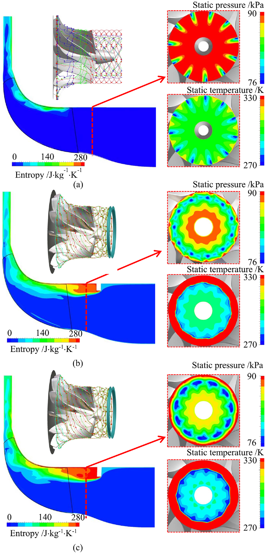
Static pressure distribution from the DES simulations for three models: (a) baseline compressor, (b) Case 1, and (c) Case 2.
Distribution of relative Mach number at the impeller inlet, the DES results: (a) baseline compressor, (b) Case 1, and (c) Case 2.
The orifice changes the static pressure distribution at the inducer inlet. Figure 11 reveals a few low-pressure regions, which means flow acceleration occurrence in front of the inducer. In the baseline, the low-pressure regions in front of the inducer are near shroud casing because of the upstream extension of the expansion and the shock waves. In Case 1 and Case 2, the low-pressure regions move to 80% span from the blade tip. Two reasons contribute to the formations of low-pressure regions in Case 1 and Case 2.
(1) the upstream extension of both the shock and expansion waves, like in the baseline compressor;
(2) the flow acceleration process caused by the throttling effect of the orifice. The main flow has a lower temperature in front of the inducer in the spanwise range from the hub to the orifice in Case 1 and Case 2 than that in the baseline compressor. The static temperature reduction means the flow acceleration.
The flow acceleration becomes more significant with the increase of the orifice height because the compressor inlet flow area gradually reduces. The combination of the expansion waves and the throttling effect of the orifice determines the temperature distribution at the inducer inlet. So, the most significant drop in static temperature occurs in Case 2, especially in the region near the inner rim of the orifice.
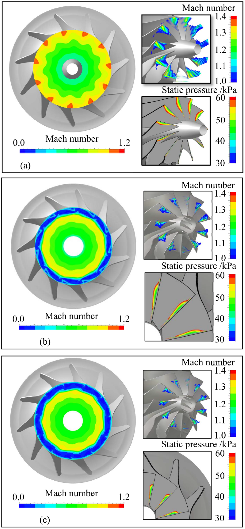
Figure 12 depicts the shock wave structures for three cases. The relative Mach number is depicted in both the inducer inlet plane and the blade passages. The static pressure is plotted on the blade suction surface to show the expansion region before the shock wave. For the baseline compressor, the peak Mach number discretely occurs near the shroud casing while it forms a whole ring shape near the inner rim of the orifice for both Case 1 and Case 2. The changed Mach number proves that the combination of the expansion wave and the orifice-induced throttling effect contributes to the formation of the lowest static pressure region and the origin of the lowest static temperature regions in Figure 11.
The orifice presence induces a radial migration of the shock wave. As the orifice height increases, the span of the shock wave migration becomes larger. Evidence supporting the shock wave migration in radius is observed from the distribution of relative Mach number ranging from 1.0 to 1.4 in the blade passage. Another piece of evidence is the static pressure distribution on the blade suction surface.
The orifice generates a ring-shaped high-pressure region near the shroud casing, as shown in Figure 11(b) and (c). The formation of the high-pressure region is attributed to the effects of the orifice. The low-energy fluid flows back to the inducer inlet duct because the orifice presence shifts the shock wave. The reverse flow has a high circumferential component of velocity, and the circumferential force contributes to the formation of the high static pressure region near the shroud casing. The extent and the size of the high-pressure region in Case 2 are more significant than in Case 1 because the increased height orifice has stronger effects on the reverse flow generation in Case 2.
In short, the orifice arranged in front of the inducer causes the reverse flow occurrence, thus increasing the static pressure in the region close to the shroud casing because of the circumferential force and shifting centripetally the shock wave from the blade tip. The static temperature increases in the vicinity of the shroud casing because of the reverse flow, while it drops in other regions because of the flow acceleration. The flow acceleration is due to the orifice throttling effect and expansion waves from the blade leading edge in the compressor with an orifice in its inlet.
Flow in impeller
The flow acceleration of the main flow in front of the inducer inlet changes the incidence angle for impeller blades. Figure 13 compares the relative flow angle at the inducer inlet. For the baseline compressor, the flow angle gradually increases from the hub to the shroud while suddenly dropping at about 75% span. The drop forms a trough in the span-wise range from 75% to shroud in both Case 1 and Case 2. The lowest flow angle occurrence corresponds to Case 2, the highest orifice. The sudden reduction in flow angle is attributed to the reverse flow that exits from the inducer inlet. Before leaving upstream the inducer inlet, the reverse flow already absorbs energy from blades, thus having a high circumferential component of velocity, as shown in Figure 13(c) and (d), and forming a pre-swirl.
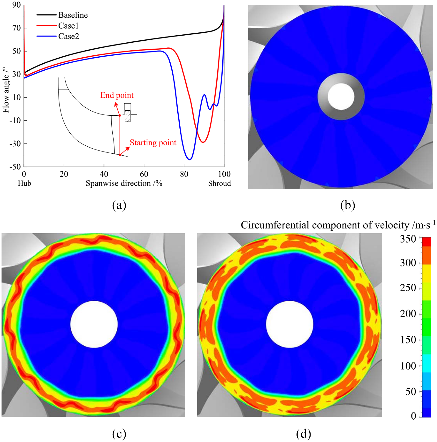
Flow angle at impeller inlet: (a) circumferential-averaged flow angle, (b) baseline, (c) Case 1, and (d) Case 2.
In the span from hub to 75% span, the orifice presence lowers the incidence angle compared to the baseline compressor, and the lowest flow angle corresponds to Case 2. The flow angle reduction is because of the increase in the axial velocity of the main flow. Therefore, it can be concluded that the flow angle reduces with the orifice height increase.
The incidence angle changes in blade tip regions redistribute the static pressure on the shroud casing, especially in the front part of the impeller, also called the axial flow section. Figure 14 compares the static pressure on the shroud casing. First, the circumferential-averaged static pressure from three cases is plotted in Figure 14(a). The x-axis is the distance from the impeller exit to the inlet. For Baseline, a significant pressure drop occurs around 38 mm on the x-axis because of the flow acceleration in inducer passages. A noticed finding is the disappearance of pressure drop in both Case 1 and Case 2, as shown in Figure 14(a).
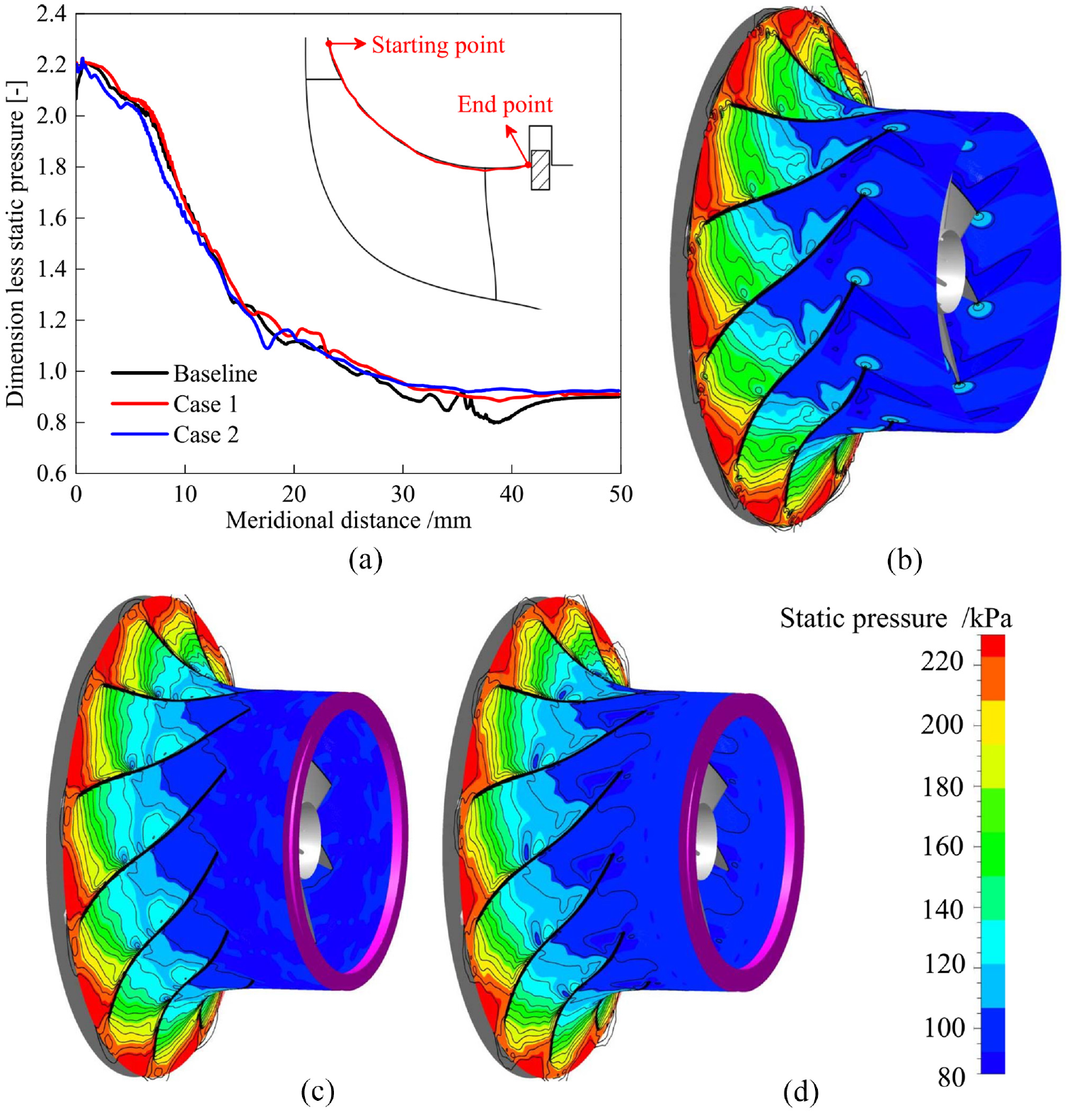
Comparison of static pressure on shroud casing for three cases: (a) the circumferential average pressure, (b) baseline compressor, (c) Case 1, and (d) Case 2.
Figure 14(b) to (d) show the detailed static pressure distribution on shroud casing for three cases. Their comparison shows that the pressure changes mainly occur on the suction side of blades. Therefore, it is concluded that the orifice raises the static pressure in the corner between the blade suction surface and the shroud casing. The increased pressure region partially explains the disappearance of pressure drop in the region after the inducer inlet in Case 1 and Case 2. In addition, the adverse pressure gradient reduces along the meridional direction on the shroud casing with the pressure change. The pressure gradient reduction is beneficial for suppressing flow separation from shroud casing and may be beneficial for the wake flow reduction because the separation flow is the origin of wake flow.
The orifice presence lowers the aerodynamic loading around the blade inlet tips and raises it around 80% chord. Figure 15 compares the aerodynamic loadings on the blade surface for three cases. The comparison shows a reduction of blade loading around inducer inlet tips for Case 1 and Case 2. The reduction is attributed to the reverse flow occurrence and the incidence angle variations (shown in Figure 13(a)).
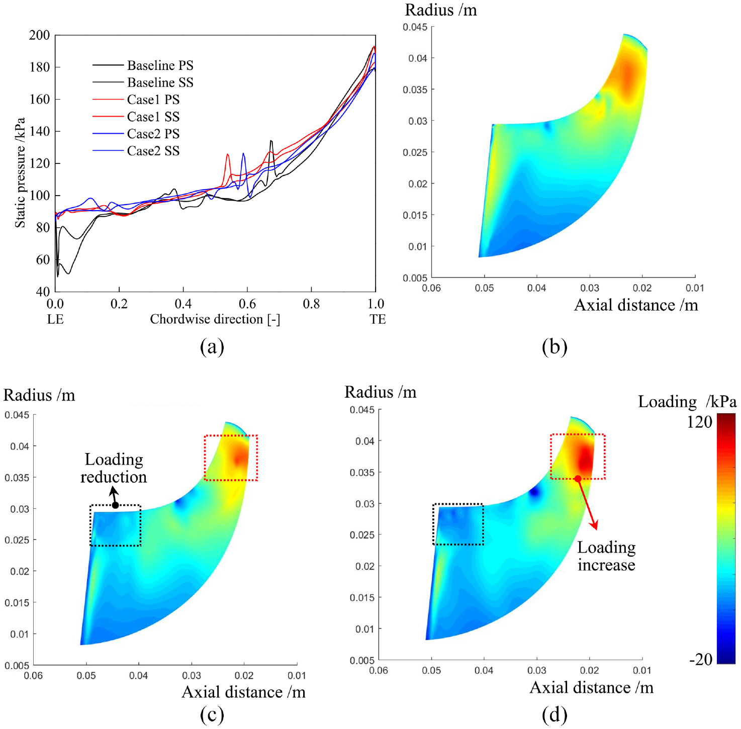
Aerodynamic loading on blade surface for three cases: (a) static pressure around blade tip, (b) baseline, (c) Case 1, and (d) Case 2.
The orifice presence contributes to the formation of the aft-loaded impeller. Figure 15 shows a significant change in blade loading around 80% chord. Compared to the baseline compressor, a significant increase in the blade loading can be observed around 80% chord in both Case 1 and Case 2. Moreover, with the orifice height increase, the improvement of blade loading becomes more significant, thus forming an aft-loaded impeller.
The blade loading variations in the region near the blade leading edge are another piece of evidence for the radial migration of the shock wave. In the baseline, the blade loadings are high near the leading edge. The peak loading is at about 80% span. In contrast, the blade loading near the leading edge reduces in Case 1 and Case 2. The peak loading around the leading edge occurs at about half span, rather than the 80% span.
The orifice presence plays a role in reducing the compressor inlet trim (R1s). In principle, a lower ratio of the impeller inlet radius (R1s) against the outlet radius (R2) mostly increases the length of the impeller channel and then is beneficial to diffuse the flow along the meridional direction on the shroud casing. The design of this sort is suitable for the compressor operating points having high-pressure ratios. It is also reported that the variable inlet flow area configuration has better controlling effectiveness for the high-trim impeller. 26 So, we suggest a higher R1s/R2 in the preliminary design of a compressor with the variable geometry orifice, which would generate a short impeller channel and, by reducing the flow fraction and even tip leakage flow, improve the compressor performance. When the channel length on the shroud side is insufficient to diffuse the flow from the impeller inlet to the outlet, putting the variable geometry orifice into action can reduce the compressor inlet flow area, thus having the compressor work like a smaller R1s/R2 impeller.
In short, the orifice influences the incidence angle at the inducer inlet, the shock wave structure, the static pressure distribution on the shroud casing, and the aerodynamic loading distribution on the blade surface. It is as if the impeller has a lower R1s/R2 value and an aft-loaded pattern after working with the orifice. Based on the findings, we propose a design suggestion of choosing a large R1s/R2 value for the compressor with a variable inlet flow area configuration.
Flow in diffuser
Figure 16 compares the flow angle at the diffuser inlet. The circumferential-averaged flow angle in Figure 16(a) reveals that the orifice decreases the flow angle in the span-wise range from 5% to 40% but increases it from 40% to the shroud. Moreover, the orifice of 4.7 mm height generates the most significant rise of flow angle in the span above 40%. Therefore, it is concluded that the orifice can better the span-wise distribution of flow angle at diffuser inlet, and the improvement of the span-wise distribution is related to the radial height of the orifice.
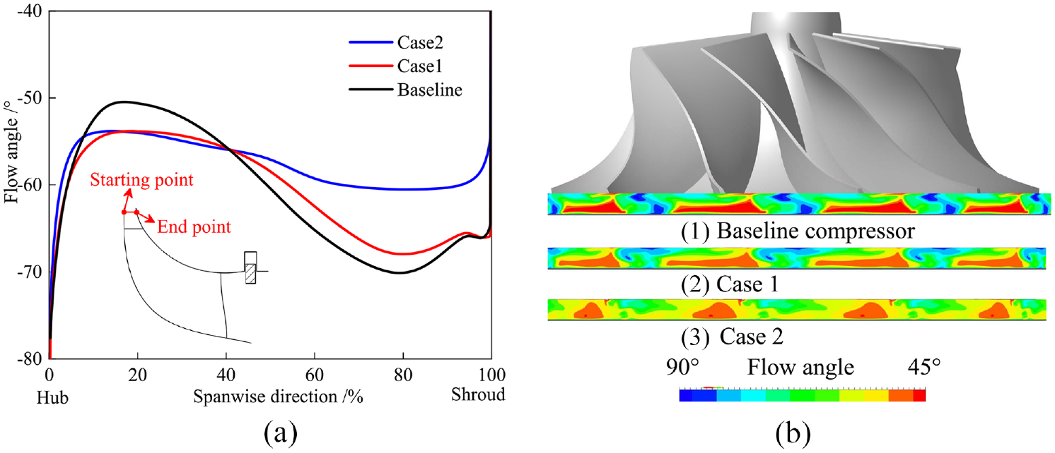
Flow angle at impeller exit: (a) circumfernetial-averaged flow angle for three cases and (b) Distribution of flow angle at impeller exit.
Figure 16(b) and (c) show the flow angle distributions at the diffuser inlet. The jet and the wake flows are apparent in the baseline compressor. In Case 1 and Case 2, however, both the extent and the size of the high flow angle regions (the wake flows) become smaller. Meanwhile, similar changes can also be observed for the low flow angle regions (the jet flows). This is consistent with the conclusion based on Figure 16(a) that the orifice presence weakens the flow distortion in the span-wise direction. In addition, the comparison of plots also reveals an improvement in the flow angle distortion in the circumferential direction.
The combination of the jet flow and the wake flow from the impeller exit determines the flow distribution at the diffuser inlet. The inlet orifice presence mainly changes the wake flow formation. As measured by Eckardt, 27 it is the corner formed by the blade suction surface and the shroud casing where the flow separation occurs under the action of the adverse pressure gradient and then contributes to the origin of the wake flow. The analysis mentioned above shows the disappearance of pressure drop at the end of the inducer passage and the pressure rise on the suction side of the blade. Consequently, the adverse pressure gradient becomes smaller, and the risk of flow separation mitigates. Even though partial flows separate from the shroud casing, they will flow upstream because of the orifice presence and then form the reverse flow instead of flowing downstream to form wake flow. The mechanism of the inlet orifice improving the flow angle distribution at the diffuser inlet is the static pressure rise in the corner between the blade suction surface and the shroud casing.
The orifice presence in the compressor inlet enhances the turbulent flow in the downstream vaneless diffuser. Figure 17 compares the distributions of the axial component of velocity at 30% span in the diffuser. The axial direction is perpendicular to the diffuser, and then the axial component of velocity can indicate the flow disturbance. Compared with the baseline model, the axial velocity distribution becomes more turbulent in both Case 1 and Case 2. The uneven distribution of axial velocity distribution means turbulence enhancement in both Case 1 and Case 2. The turbulent flow enhancement should be related to the formation of the aft-loaded impeller. More impeller work is transferred to the fluid in the second part of the impeller channel.
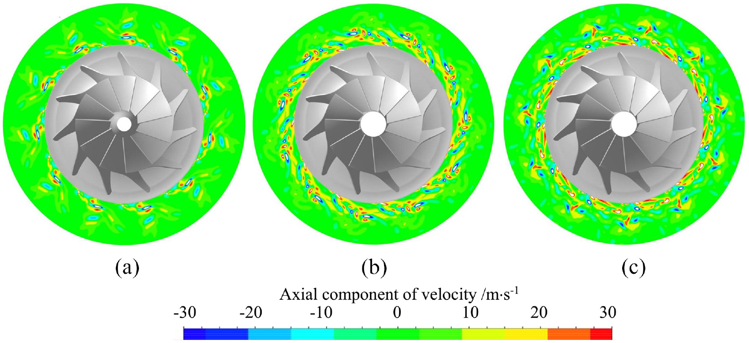
Axial component of velocity in the diffuser at 30% span for three cases: (a) baseline, (b) case 1, and (c) case 2.
In short, as far as the deterministic flow, the inlet orifice presence reduces the flow distortion at the diffuser inlet, including both the circumferential and the radial directions. With the orifice height increase, the difference in flow angle between the jet and the wake regions becomes smaller, and the flow distribution becomes better in the flow evenness. In terms of flow turbulence, the orifice enhances the turbulent flow in the diffuser.
Conclusions
This paper analyzed the effects of the orifice on a centrifugal compressor using experiments and numerical simulations. The main conclusions based on the DES results are drawn as follows.
(1) The inlet orifice covers the partial flow area in the compressor inlet and changes incoming flow behaviors at the inducer inlet. In the covered region, the changed flow behaviors comprise the reverse flow occurrence and the shock wave disappearance. In the uncovered region, the changed flow behaviors include the acceleration process of the main flow in front of the inducer, the decreased incidence angle of the main flow, and the reduced blade loading in the regions near the leading edge.
(2) In the impeller section, the inlet orifice presence in the compressor inlet causes the static pressure rise in the corner between the blade suction surface and the shroud casing, the reduction of adverse pressure gradient on the shroud casing behind the inducer, the blade loading reduction around blade inlet tips, and the formation of the aft-loaded impeller.
(3) The orifice presence changes the distribution of both wake and jet flows at impeller exit/diffuser inlet and improves the flow distribution at diffuser inlet in terms of uniformity. The mechanism is that the orifice changes the static pressure gradient in the corner between the shroud casing and the blade suction surface. The pressure gradient on the shroud casing surface plays a vital role in the flow separation that is the wake flow origin.
(4) The orifice presence in the compressor inlet enhances the turbulent flow in the vaneless diffuser. The mechanism is that the aft-loaded impeller formation allows more energy to be transferred into the fluid in the downstream part of the impeller. The turbulence enhancement in the diffuser is a novel finding, which requires us to adopt the DES rather than URANS.
A suggestion is proposed for the design of variable geometry centrifugal compressor. In the preliminary design, we suggest a large R1s/R2 for the compressor performance improvement at the operating points of the low-pressure ratio. Once the short impeller channel length caused by the large R1s/R2 selection is insufficient to diffuse flow on the shroud side, the variable inlet flow area configuration should be put into action.
Footnotes
Declaration of conflicting interests
The author(s) declared no potential conflicts of interest with respect to the research, authorship, and/or publication of this article.
Funding
The author(s) disclosed receipt of the following financial support for the research, authorship, and/or publication of this article: This study was financially supported by the national natural science foundation of China (Grant No. 52006217) and (Grant No. 51736001).