
Abstract
Numerical studies of a marine diesel engine intake silencer are conducted to evaluate its performance, and effects of the silencer on the turbocharger compressor performance are also discussed. The results show that the duct acoustic mode method can be used in the silencer transmission loss prediction, and the predicted noise reduction and main frequency range agree with the measurements fairly well. However, it is found that the silencer compromises the compressor performance by shortening its operating range. It is found that the static pressure on the compressor blade surface is decreased, thus the compressor total-to-total pressure ratio and isentropic efficiency are reduced. Pressure fluctuations at compressor rotor and stator inlets enhanced when a silencer is installed, which means the trend of pressure spectrum in the rotor and stator passage is changed. Compared with the results of a compressor in natural aspiration, it is found that the silencer can significantly reduce high-frequency noise. In particular, it is quite effective in tonal noise reduction. In addition, the compressor inlet noise spectrum indicates that noise radiation characteristics are different with a silencer installed.
Introduction
Turbochargers are widely used in marine low-speed diesel engines, and it can improve the in-cylinder combustion, increase the engine output power, and reduce the fuel consumption and exhaust emission. 1 Although the turbocharging technology is necessary in marine diesel engines, it also has some negative effects, for example, high cabin noise. Recently, the requirements of marine cabin noise are becoming more stricter, so the marine diesel engine noise control becomes a trending topic. The existing literature shows that main noise sources of turbocharging diesel engines consist of mechanical noise, combustion noise, and aerodynamic noise.2–4 The mechanical noise can be reduced by optimal designs of crank train, value train, and other moving components; while the combustion noise has been significantly reduced by the use of electronically controlled injection system.5,6 As a result, the aerodynamic noise, specifically turbocharger noise, becomes the prominent issue in marine diesel engine noise.
Tremendous attention has been paid to turbocharger in the past decades. Li and Liu both studied turbocharger noise characteristics through experiments, and they found that the main noise source of turbocharger is the compressor noise, rather than turbine noise or structural radiation noise.7,8 Moreover, the applications of the exhaust silencer and the acoustic enclosure significantly reduce the turbine noise and structural radiation noise.9–11 Raitor and Neise carried out experiments to investigate the compressor noise generation mechanisms. On the compressor inlet side, the compressor noise is dominated by tip clearance noise (TCN) with low rotating speeds, and the main feature is tonal noise (noise peaks occur at shaft rotation frequency, blade passing frequency, and its harmonics) at sonic Mach number. Furthermore, tonal noise and buzz-saw noise (noise peaks occur at shaft rotation frequency and its harmonics) become the main noise sources in supersonic flow conditions. 12 Meanwhile, broadband noise can be obtained within the entire frequency range of interest. Several narrow bands were detected at 1.5–3.5 kHz in compression–ignition engines and at 5–7 kHz in spark-ignition engines.13–16 In summary, the compressor noise components are complex, and the main noise source varies with operating conditions. Therefore, the effective control of compressor intake noise is difficult.
Nowadays, intake silencers are adopted to reduce the compressor intake noise. There are different kinds of silencers for different noise sources, including reactive silencer, dissipative silencer, and their combinations. The sound energy in the reactive silencer is consumed by the reflection, and the interference induced by duct impedance changes. In addition, the sound energy in the dissipative silencer is transformed into heat energy through the friction between the sound wave and sound absorbing materials. Lee et al. 17 designed a multi-chamber silencer, and the experimental and analytical results showed that it is effective in whoosh noise control. Abom and Kabral developed a compact dissipative silencer, which is based on a combination of a micro-perforated tube and a locally reacting cavity. In more than an octave, noise reduction was more than 30 dB for its high damping effects.18,19 Tian et al. 20 introduced a reactive silencer to reduce turbocharger synchronous noise, and the results obtained in a vehicle test indicated that the silencer can reduce noise effectively in the frequency range of 1000–5000 Hz. The aforementioned researches obtained many benefits from the compressor intake noise control, but they mainly concentrated on the automotive turbocharger broadband noise. There are only few literatures focusing on the performance of turbocharger compressor intake silencers of marine diesel engines.
Many publications assume that the inlet flow field is stable; therefore, the effects of the inlet distortion are neglected.21–23 However, in a real condition, the intake pipelines or silencers mounted in the compressor inlet would change the uniformity of the intake air, thus the compressor performance is closely related to the impeller inlet flow. It is necessary to study the effects of inlet distortion induced by intake pipelines or silencers on the compressor performance. Galindo et al. 24 investigated the effects of intake pipelines on automotive turbocharger compressor, and the results showed that pressure ratio and isentropic efficiency of a compressor are reduced by increasing the pipeline length or decreasing the pipeline diameter. Serrano compared effects of the straight duct, the elbow, and elbow with guide vanes on turbocharger performance and operation stability. It is found that the air intake uniformity and total pressure loss are two deciding factors of the compressor performance. 25 Yang, Li, and Wang further studied the effects of elbow shapes and their installation positions on a centrifugal compressor. This study gave suggestions for the optimal design of an intake pipeline.26–28 For turbocharging marine diesel engines, the airflow inlet is located at the cabin, so the intake silencers are necessary for cabin noise control. The compressor performance is influenced by the complex inlet flow that is caused by intake silencer, so it is necessary to study the effects of an intake silencer on the compressor performance.
The performance of a marine diesel engine turbocharger intake silencer and the effects of silencer on turbocharger compressor were analyzed in this article. First, the intake noise characteristics of marine diesel engine turbocharger compressor were experimentally investigated, and the intake silencer structure was also designed. Then, the intake silencer performance was studied, such as total pressure loss and transmission loss (TL). Furthermore, the effects of the silencer structure on the compressor global performance, unsteady flow characteristics, and intake noise were numerically analyzed. All analysis methods are shown in Figure 1.

Research flow diagram.
Design and numerical analysis of intake silencer
Turbocharger intake noise characteristics
The turbocharger intake noise characteristics were measured in a turbocharger performance test bench, which is shown in Figure 2. In order to eliminate the influence of other noise sources, the turbine outlet was directly connected to the outside, and all connecting pipelines and turbocharger housing were isolated using acoustic materials. The compressor intake noise was tested under the natural aspiration condition to obtain the original measurement results. The measurement points were also shown in Figure 1. The location of measurement points is higher than 1 m from the floor, which was also isolated by the acoustic material. Therefore, the ground reflection effects were eliminated. Furthermore, the environment correction was conducted in experimental results analysis to take into account the effects of acoustic reflection on measured sound pressure level (SPL). All the five measurement points are arranged in semicircle with counter-clockwise distribution. The microphones manufactured by BSWA TECH (Model MPA401) were used to measure the compressor intake noise. Data were analyzed by the B&K 3560D data acquisition front-end and B&K PULSE 12.6 software analysis system, respectively.

Experimental equipment of compressor intake noise measurement.
The intake noise characteristics at compressor design speed are shown in Figure 3. It can be clearly found that the tonal noise and buzz-saw noise are the main noise sources, and the tonal noise is the dominant spectral component. The compressor intake noise has high SPL in nearly entire frequency range (0–10 kHz), especially at high frequencies like blade passing frequency (BPF, the definition is shown as in equation (1)) and its harmonics

Intake noise characteristics at design speed: (a) linear spectrum and (b) one-third octave spectrum.
Intake silencer design
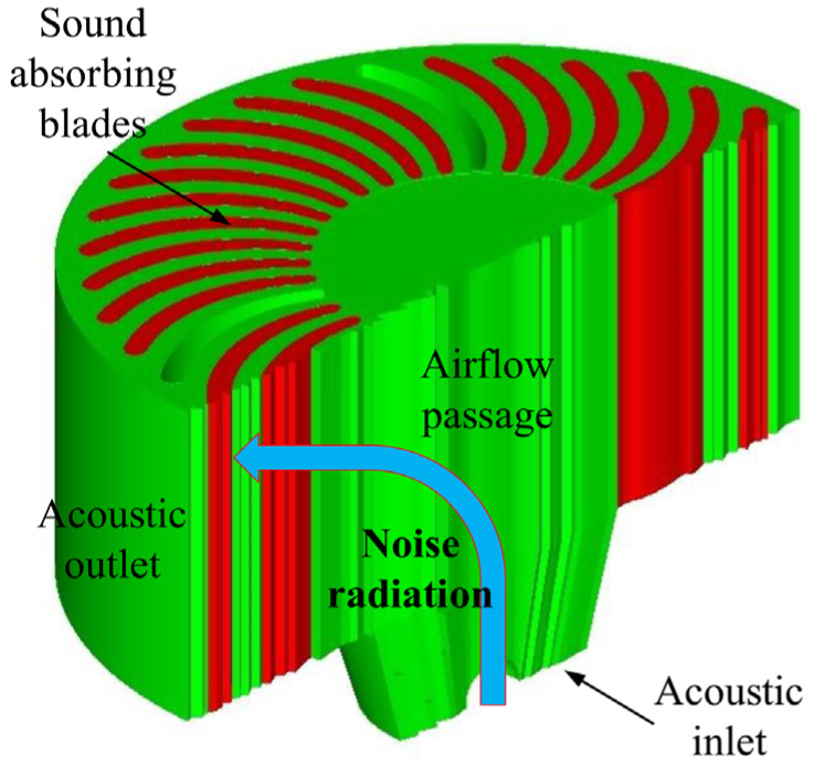
In this article, the intake silencer structure is shown in Figure 3, and its design is based on previous studies.29–31 The silencer consists of the front wall, the end wall, 33 sound absorbing blades, 3 ribs, and other additional structures, as shown in Figure 4. The size of the temperature measurement hole, pressure measurement hole, oil gas suction hole, and cleaning water pipe is small. Hence, all of these components are neglected in the silencer calculation model.

Cutaway view of intake silencer: (a) vertical section and (b) cross section.
In order to obtain acoustic cavities with different volumes, the arrangement of ribs is not equidistance. The sound absorbing material used in the silencer is aluminum silicate wool. The airflow direction of the intake silencer is same as the radial direction, which can guarantee noise reduction, increase the airflow passage, and filter the air.
Numerical analysis of intake silencer performance
Two most important parameters of a silencer are the resistance performance and noise reduction. The former often refers to the total pressure loss between the silencer inlet and the outlet. The latter has different evaluations, including TL and insertion loss (IL). 32
The TL is defined as the difference between the incident sound power level on silencer acoustic inlet plane and the transmission sound power level on the silencer acoustic outlet plane, as shown in equation (2). This parameter is often used in numerical calculations
The IL is defined as the difference between the SPL (or sound power level) obtained at a fixed measurement points before and after the silencer was installed, as shown in equation (3). This parameter is often used in experimental analyses

Pressure loss
The flow field model of the intake silencer is shown in Figure 5, and the structure of sound absorbing blades and ribs is removed to obtain the airflow passage. Because this model is also used in the calculation of compressor performance with silencer installed, the compressor rotor shaft head is considered in the numerical model. The overall mesh consists of 1.18 million structured hexahedral cells, in order to satisfy the requirement of near wall y+ value that limits to 1.

Flow field model of intake silencer.
The three-dimensional steady flow of intake silencer was simulated by ANSYS CFX. K-omega shear stress transport (SST) turbulence model was employed, thus the boundary conditions near the solid walls were not analyzed by the standard wall function that was used for rough meshes. The inlet boundary condition was set as fixed inlet pressure and fixed inlet temperature. The outlet boundary conditions were set as fixed mass flow rate. The air property was set as ideal gas. The solid wall roughness was set as 50 µm. As shown in Figure 6, the total pressure loss induced by intake silencer was calculated under eight different operating conditions, and the volume flow rate covered the entire compressor operating range.

Total pressure loss caused by silencer.
The total pressure loss is defined as the total pressure difference between the silencer inlet and the outlet, including the pressure loss caused by the pipeline of the silencer outlet and the sound absorbing structure. The pressure loss caused by the silencer outlet pipeline is eliminated in the corrected pressure loss to show the resistance performance of sound absorbing structure. The total pressure loss increases with the increase in the volume flow rate. The results show that the corrected pressure loss is lower than 1000 Pa in nearly the entire flow range, which means the intake silencer design is feasible.
TL
The sound absorbing material used in the silencer is aluminum silicate wool. The acoustic characteristics of aluminum silicate wool were experimental measured by B&K-4206T impedance tube, as shown in Figure 7(a). The experimental method was referred to ISO 10534-2. 32 The complex impedance ratio and complex wavenumber ratio were shown in Figure 7(b) and (c). The experimental data were treated with curve fitting. The empirical formula of the acoustic characteristics of aluminum silicate wool was obtained as follows


Experimental measurement of acoustic characteristics of aluminum silicate wool: (a) impedance tube (B&K-4206T), (b) complex impedance ratio, and (c) complex wavenumber ratio.
In the TL calculation using traditional finite element method (FEM), such as commercial software LMS Virtual.Lab, where the acoustic inlet is defined as unit particle velocity 1 m/s, the acoustic outlet is set as non-reflection boundary. In this situation, single node on the inlet plane and the outlet plane is selected to represent the entire plane, and a good result can be obtained in the frequency range of plane wave. However, the sound wave radiation is affected by the structure, size, and material of the silencer duct. Therefore, the high-order waves in the silencer must be considered. Although these boundary conditions can fully describe the sound field and acoustic model in the silencer, there are still some limitations.
The duct acoustic mode method is used in this article to predict the TL of intake silencer, which is also based on FEM. However, this method is able to take into account the high-order waves. The numerical model is shown in Figure 8, in which the acoustic inlet is defined as a sound wave represented by acoustic mode, the acoustic outlet is set as automatically matching layer (AML), and the TL is calculated with equation (2). All simulations were completed using commercial software LMS Virtual.Lab.
Numerical model for silencer TL prediction.
Based on the definition of TL and the acoustic decomposition theory, the incidence sound pressure of grid cell m on inlet plane and the transmission sound pressure of grid cell n on outlet plane are defined as follows


Thus, equation (2) can be rewritten as

The maximum frequency in this article is 10 kHz, and the mesh grid size can be calculated using the Nyquist sampling theorem as follows

The sound velocity at 298 K is 344 m/s, and thus, the maximum mesh size is 5 mm. In the TL calculation with the duct acoustic mode method, all the modal waves were used to describe the sound wave propagation. If the calculation frequency is higher than the cut-off frequency of a certain order mode, the certain order modal wave can propagate in the silencer. Otherwise, the certain order of mode wave is attenuated rapidly. The cut-off frequency is calculated as follows
The
Equation (10) is applicable to circular pipelines, and it can be used to set the acoustic inlet boundary in the intake silencer TL calculation because the acoustic inlet of intake silencer was a circular plane. The modal wavenumber of acoustic model was shown in Table 1. The amplitude and the phase of every mode used are set as 1 and 0 W, respectively.
Modal wavenumber of acoustic model (m, n).

Air density is 1.225 kg/s, and speed of sound is 344 m/s. Multiple high-order acoustic modes were used in the acoustic inlet, which is shown in Table 1. The acoustic outlet is set as AML boundary, and all the other walls were set as rigid wall.
The TL calculation result is shown in Figure 9, and the intake silencer can achieve a significant noise reduction. The TL values of octaves are higher than 20 dB in the frequency range of 2–10 kHz. Limited to the silencer structure size, the noise reduction is lower than 10 dB in the frequency range of 0–1 kHz.

Transmission loss of intake silencer.
Experimental verification
Silencer static acoustic test was conducted to validate the numerical result, and the test bench is shown in Figure 10. The noise source, connecting pipeline, and intake silencer are arranged in a straight line, which makes the sound wave directly propagates through the connecting pipeline to the intake silencer.
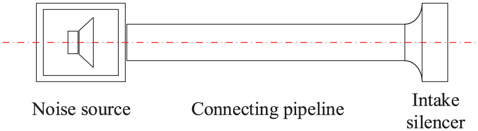
Silencer static acoustic test bench.
The measurement points’ arrangement is shown in Figure 11, and there were four microphones located at the measurement surface, and the experiments were conducted with intake silencer and substitution pipe, respectively.
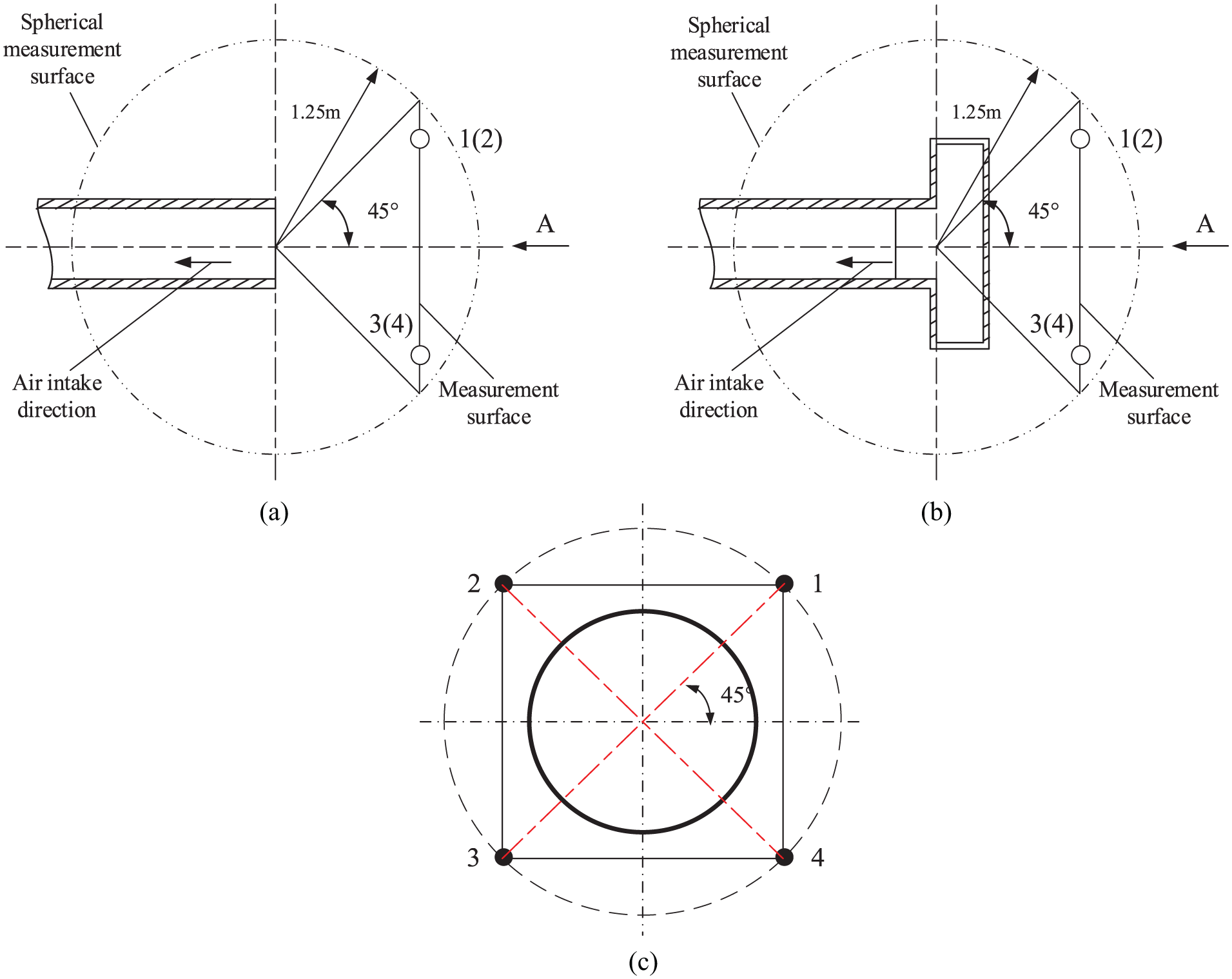
Positions of noise measurement points: (a) substitution pipe, (b) silencer, and (c) measurement surface (view of section A).
Figure 12 shows the comparison of the experimental and calculated silencer IL. It can be found that the IL values in high frequency (2–10 kHz) are also more than 20 dB, which indicates that the silencer can reduce high-frequency noise effectively. Meanwhile, the comparison of calculated IL and measured IL shows that the main noise reduction frequency range and noise reduction values are similar. The total calculated and measured IL is 31.68 and 33.55 dB, respectively.

Insertion loss of intake silencer.
Effect of the silencer on compressor performance
Compressor global performance
The intake silencer is mounted to the compressor inlet, as a part of marine diesel engine turbocharger. The original compressor structure is composed of the inlet duct, impeller, diffuser, and volute. The principle geometric structure and parameters of the compressor used in this article are shown in Table 2.
Compressor geometric parameters.

A three-dimensional numerical model of the centrifugal compressor was established by ANSYS CFX. The impeller was discretized along with the inlet duct, vane diffuser, and volute, and the tip clearance of the impeller was also considered in the computational fluid dynamics (CFD) model. To better calculate the compressor unsteady flow details, local mesh refinement and boundary layers were applied in the complex flow area. Three domain interfaces were defined between the inlet duct–impeller, impeller–diffuser, and diffuser–volute, which facilitated the compressor flow calculation. The numerical model of compressor under natural aspiration condition is shown in Figure 13. The grid independence analysis at compressor design operating condition is shown in Table 3. It can be found that the medium mesh is sufficient for numerical simulations. When the silencer is installed, the inlet duct is replaced with the numerical model of silencer, which is shown in Figure 5.

Numerical model of compressor natural aspiration.
Mesh independence analysis (compressor design operating condition).

The three-dimensional compressor steady flow was simulated using Reynolds-averaged Navier–Stokes (RANS) k-omega SST model. The fixed inlet pressure, inlet temperature, and outlet pressure boundary conditions were used, but when the operating conditions moved toward the surge line, the fixed inlet mass flow rate and temperature were applied to ensure the convergence of the numerical computation.33,34 As shown by the previous studies, heat transfer between the high-speed compressors and their surroundings can be neglected, 35 thus all wall conditions in the numerical model were set to adiabatic.
The variation of compressor performance is shown in Figure 14. Under the natural aspiration condition, the comparison of the experimental measurement and the numerical calculation indicates that the numerical results are accurate. The numerical model can be used in the discussion of the effects of the silencer structure on compressor performance.
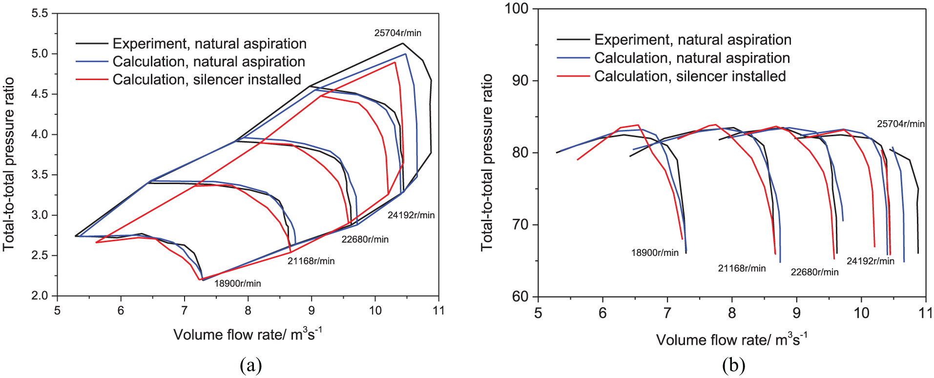
Variation of compressor performance: (a) total-to-total pressure ratio and (b) isentropic efficiency.
When the intake silencer is installed, the maximum volume flow rate at every speed line (choke line) reduced, the surge line moves to high flow rate, and the reduction in compressor flow range is nearly 0.4–0.5 m3/s. Thus, the compressor operating range was shortened. The high-efficiency area also decreases, and the maximum efficiency moves to the surge line, which is not ideal for compressor operations. Meanwhile, compared with the results of compressor natural aspiration, the total-to-total pressure ratio and efficiency at the same speed and flow rate decrease. With the increase in compressor speed, the trends become more obvious. The analysis results above indicate that intake silencer has a great influence on compressor performance.
In order to further explain the diminishing compressor performance when the intake silencer is installed, the compressor rotor blade load is discussed. The blade load capacity can be expressed by the static pressure distribution of compressor rotor blade surface. It is shown in Figure 15 that the static pressure decreases when the silencer is installed. Furthermore, with the compressor operating condition moves to the surge line, such downtrend of static pressure is more obvious.

Static pressure distribution of compressor rotor blade surface at 50% span, design speed, natural aspiration (black line), and silencer installed (red line).
Because the airflow at the impeller inlet is approximately one-dimensional flow, the one-dimensional pipe flow formula can be referred

Under the condition of same flow rate and the total temperature, the total pressure at impeller inlet decreases when pressure loss increases, thus the axial flow coefficient q and axial velocity increase. If the rotating speed is the same, high axial velocity makes the attack angle to diverge from the design value, which means the compressor load is reduced.
Under a natural aspiration condition, there is only a straight short duct in front of the impeller inlet. The resultant total pressure loss is much less than that when the silencer is installed. The total pressure loss induced the compressor rotor blade load reduction and decreased the total-to-total pressure ratio and efficiency at the same speed and flow rate, which are shown in Figure 14.
The static pressure distribution on compressor rotor blade surface at near-surge conditions in different operating speeds is shown in Figure 16. The total pressure loss increases with the rotating speed, so the trend of static pressure is also more obvious with the rotating speed.
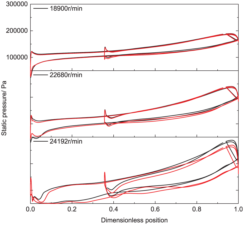
Static pressure distribution of compressor rotor blade surface at 50% span, near-surge conditions at different operating speeds, natural aspiration (black line), and silencer installed (red line).
Compressor unsteady flow characteristics
The three-dimensional unsteady flow of the compressor was simulated under the design operating condition. The total time of every calculation is 0.025 s, which is more than eight impeller revolutions. The time step size can be calculated by the sensitivity analysis conducted by Navarro, 16 which suggested that the impeller rotates no more than 1° in each time step. The time step size used in this article is 5e-6 s, in order to obtain accurate unsteady flow results. The pressure fluctuation at rotor inlet and stator inlet is monitored, and the results are shown in Figures 17(a) and 18(a). The compressor blade rotation caused periodic pressure fluctuation, and every rotating blade leads to a fluctuation peak. The pressure fluctuation amplitude peaks appear at BPF and its harmonics, as shown in Figures 17(b) and 18(b). The pressure fluctuation at rotor inlet is mainly affected by the main blades. Although the splitter blade has less effects than the main blade, the pressure fluctuation at stator inlet is affected by both main blades and splitter blades.
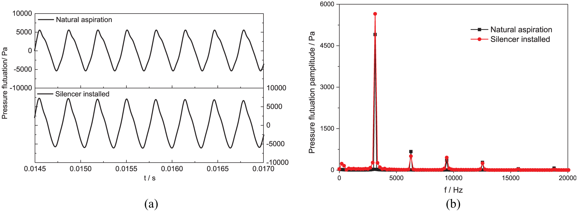
Pressure fluctuation at monitoring point of compressor rotor inlet: (a) time domain and (b) frequency domain.

Pressure fluctuation at monitoring point of compressor stator inlet: (a) time domain and (b) frequency domain.
Compared with the numerical results under natural aspiration condition, the pressure fluctuation at both rotor inlet and the stator inlet increases after the intake silencer is installed. The pressure fluctuation increases more than 1500 and 8000 Pa at compressor rotor and stator inlet, respectively. According to equation (7), under the condition of same flow rate and the total temperature, the total pressure at impeller inlet decreases when pressure loss increases after silencer is installed, thus the axial flow velocity increases, and the interaction between the inlet airflow and blades is stronger.
Furthermore, the pressure fluctuation was induced by the interaction between inlet flow air and rotating blades, and the total pressure loss at blade inlet plane was nearly uniform, thus the interaction between inlet airflow and different blades was nearly the same and the time period was closely related to compressor rotating speed, which would represent a significant pressure amplitude peak at shaft rotation frequency. The above phenomena indicate that the flow structure of the compressor becomes more complex when the intake silencer is installed, and these results can also prove that the effects of intake silencer on compressor performance should not be neglected.
Compressor noise reduction
In this article, FEM was used to predict the compressor noise. The pressure fluctuation at each grid node on the impeller inlet plane was monitored at each time step in the unsteady flow calculation. The pressure fluctuation was transformed to a simplified dipole source via fast Fourier transform (FFT). According to the theory of aero-acoustics, compressor noise sources can be divided into monopole, dipole, and quadrupole sources. The dimensional analysis of the fluid noise source indicates that the dipole source is the main noise source, and the monopole source and the quadrupole source can be neglected.36,37
The numerical models for compressor noise prediction are shown in Figure 19, which are referred to the positions of the measurement points displayed in Figure 11(a) and (b). The diameter of compressor impeller inlet is 0.322 m and the maximum diameter of the silencer is 0.96 m; thus, the radius of the spherical measurement surface is set as 1.25 m. All four noise calculation points are arranged as shown in Figure 11(c), and they are placed in the noise calculation domain.

Numerical model of compressor noise: (a) natural aspiration and (b) silencer installed.
The pressure fluctuation on impeller inlet of 2837 time steps are used for noise prediction in all cases, the corresponding total time is 0.01437s, and the frequency resolution is 69.6 Hz. The dipole source is attached to the noise source surface (acoustic inlet), the acoustic outlet is defined as AML boundary, the air material property is defined in noise calculation domain, and all solid walls are set as rigid wall. When the silencer is installed, the acoustic property of aluminum silicate wool is defined in the calculation domain of sound absorbing blades.
The compressor intake noise spectrums are shown in Figure 20. It is found that the tonal noise and broadband noise are main components of compressor noise spectral. Because only the dipole source is used in the calculation, the buzz-saw noise cannot be found in the spectrum. After the silencer is installed, the SPL of compressor noise reduces in nearly whole frequency range, especially in high frequency like BPF and its harmonics.
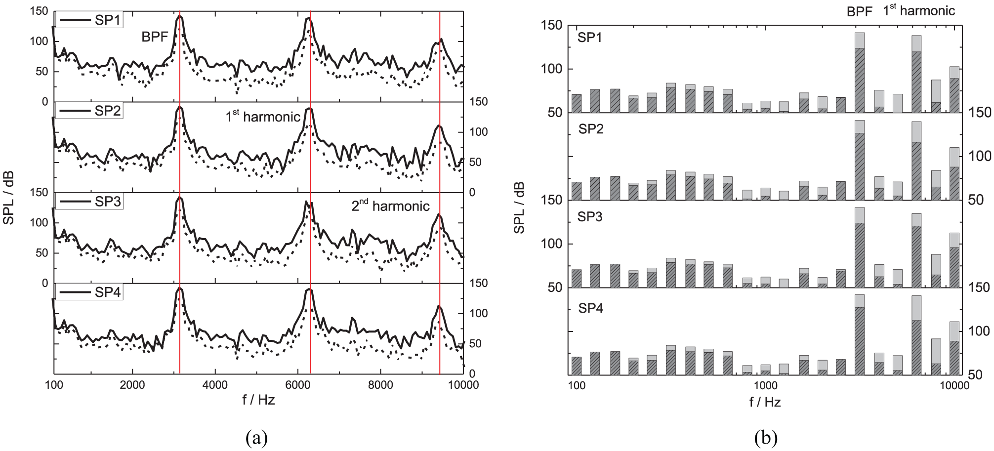
Compressor intake noise spectrum: (a) linear spectrum, natural aspiration (solid line), and silencer installed (dash line). (b) One-third octave spectrum, natural aspiration (light gray), and silencer installed (deep gray).
According to the definition of IL, the difference between the mean SPL of all four noise calculation points before and after silencer is installed can be used as the silencer IL. The numerical result of the silencer IL is obtained from the results shown in Figure 20(a), and the SPL is the mean value of all four noise calculation points. The comparison of experimental and calculation results is shown in Figure 21, and the experimental result has been smoothed by moving average approach to make a common frequency for the comparison of experimental and numerical results. Although there were errors in 1000–4000 Hz, the experimental and calculated IL agrees well in low- and high-frequency range. This indicates that the FEM calculation can also be used in silencer IL prediction, especially within high-frequency range. The total calculated and measured IL is 44.78 and 43.98 dB, respectively.

Insertion loss spectrum of silencer.
The SPL distribution of compressor noise at the inlet area is shown in Figure 22. The results under the natural aspiration condition indicates that the compressor noise distribution is not uniform when it transmits outward the compressor inlet, and there exists obvious acoustic directivity. After the silencer is installed, its structure changes the noise radiation characteristics, and the compressor noise distribution is much more uniform when it transmits outward the compressor inlet. Furthermore, the sound power is significantly reduced in the silencer.
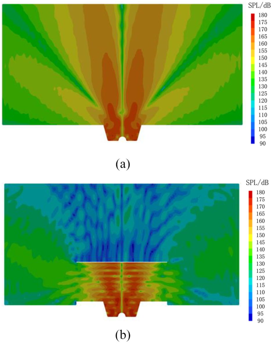
Sound pressure level distribution of compressor noise at inlet nozzle, BPF: (a) natural aspiration and (b) silencer installed.
Conclusion
Numerical and experimental studies are conducted to investigate the performance of turbocharger intake silencer. The effects of the silencer structure on the turbocharger compressor performance are also analyzed, including compressor global performance, unsteady flow characteristics, and intake noise. Conclusions are summarized in the following.
The duct acoustic mode method can be used to predict the TL and IL of intake silencer, the numerical results are in good agreement with the measurements, and the discrepancy between total calculated IL and measured IL is lower than 2 dB.
The silencer results in greater total pressure loss than that of the natural aspiration, which is higher than 1000 Pa in high flow range. The total-to-total pressure ratio and efficiency at the same speed and flow rate decrease when silencer is installed, and the reduction of flow range is higher than 0.4 m3/s. Meanwhile, the high-efficiency area reduces.
The pressure fluctuation at compressor rotor and stator inlet increases when the intake silencer is installed, and the increased pressure value is higher than 1500 and 8000 Pa, respectively. The pressure spectrum in the rotor and stator passage changes, and a pressure peak appears at the rotor shaft rotation frequency.
The noise spectrum indicates that the silencer structure changes the noise radiation characteristics. Compared with the results under the natural aspiration, the silencer can significantly reduce the high-frequency noise, and it is especially effective in tonal noise reduction. The intake silencer IL can also be predicted with CFD and FEM results; the total calculated and measured IL are 44.78 and 43.98 dB, respectively.
Footnotes
Appendix 1
Acknowledgements
The authors acknowledge the help of Yuejun Shi, who works in the Department of Mechanical and Aerospace Engineering, University of California, Davis.
Handling Editor: Jose Ramon Serrano
Declaration of conflicting interests
The author(s) declared no potential conflicts of interest with respect to the research, authorship, and/or publication of this article.
Funding
The author(s) disclosed receipt of the following financial support for the research, authorship, and/or publication of this article: This study received financial supports from Marine Low-Speed Engine Project–Phase I.