
Abstract
This paper presents a new prototype system capable of automated disc brake squeal suppression using a method of varying the leading and trailing piston pressures in a multi-piston opposed brake caliper. The new system consists of a novel modular four-piston brake caliper, a two-channel brake actuation system and an advanced control system that is capable of varying the leading/trailing pressure ratio (LTPR) when squeal is detected. The amended LTPR results in movement of the centre of pressure (CoP) position at the pad/disc interface, which leads to new dynamic parameters of the brake system and thereby to different squeal propensity. Moreover, the control system maintains the overall brake torque at a constant value, so the variation of the LTPR on the brake performance is minimised. Experiments using the current disc brake setup showed that by varying the LTPR, thereby changing the CoP position, the squeal occurrence can be successfully controlled. Large leading or trailing offsets typically lead to a quieter brake. Tests demonstrating operation of the proposed squeal control system in an automatic mode reduced the squeal occurrence significantly for a given duty cycle.
Introduction
Brake squeal is a relatively high frequency noise (>1 kHz) that frequently emerges during operation of friction brakes and is still regarded as one of the most challenging problems in the brake industry. This is often due to the fugitive nature of the actual phenomena and the necessity to adopt a multidisciplinary approach for its comprehensive understanding. The current research community is in agreement that brake system dynamic instability is the fundamental cause of brake squeal generation. 1 Generally, brake squeal does not incur a decrease of braking performance, but represents an annoying burden on vehicle occupants and passers-by, also often contributing to overall noise pollution, particularly in urban areas. Furthermore, squealing brakes are associated by most drivers with a malfunctioning system and are therefore the subject of numerous warranty claims that account for additional costs for the car manufacturers. 2
To tackle this problem, great endeavors have been made by many researchers to understand the squeal creation mechanism and numerous theories have been proposed. 3 The majority of research in this field is aimed at finding passive measures to reduce or eliminate brake squeal. This includes geometry modifications, 4 adoption of appropriate materials5,6 or adding components to modify vibrational performance, such as damping shims or grease. 7 A passive approach may sound justifiable as it minimises the brake system complexity, thereby total mass and costs, but it might fail to reduce squeal if the environmental or brake system conditions change.
During braking, the position of the centre of pressure (CoP) at the brake pad/disc contact area is typically slightly offset towards the leading side of the brake pad as shown in Figure 1. In recent experimental studies, it has been observed that this CoP position is more susceptible to squeal generation, whereas experiments with deliberate shift of the CoP out of this zone created a stable and quiet brake. For example, Fieldhouse et al. 8 used a 12-piston opposed caliper to study influence of the CoP position on the squeal performance and found that certain zones for the CoP can be identified that lead to a quieter brake. Park et al. 9 designed a four-piston opposed laboratory caliper, which is capable of independent pressure setting in each piston, to study the influence of the leading and trailing CoP offset on squeal occurrence. They observed that the squeal was readily generated with a higher pressure value at the leading pistons resulting in a leading CoP offset. An adjustment of the CoP position to minimise squeal propensity is also known in bicycle brakes where pads are often toed-in to initiate the first contact with the rim on the leading side of the pad. 10
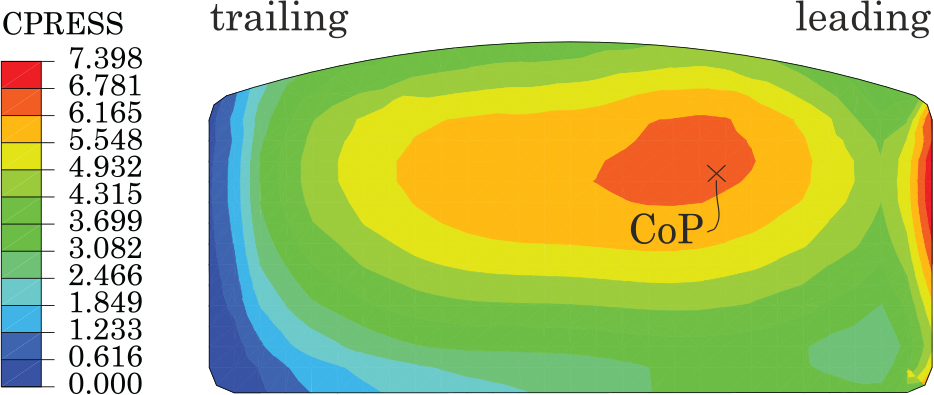
A typical non-uniform pressure distribution over the brake pad during a braking event. The contact pressure values are in MPa.
Several studies focusing on active brake squeal control using piezoelectric actuators have been presented in the literature. Cunefare et al. 11 developed a dither open-loop control system, containing a piezoelectric stack actuator placed in the piston, to actively eliminate brake squeal. A piezoelectric actuator attached to the backplate was used by Hochlenert 12 and Wagner et al. 13 who developed a new dynamic non-linear model of a brake system and an active closed-loop control strategy to suppress brake squeal. Hashemi-Dehkordi et al. 14 applied a lumped parameter model consisting of a brake pad and a conveyor belt representing a rotating brake disc to simulate a closed loop control using an active force control and PID controller. In further experimental studies, it was shown that the dither signal can reduce the effective braking torque by 3% to 5%, 15 whereas a theoretical model predicted as much as 10% reduction. 16 Such a reduction in braking torque could be a serious obstacle to implementing this system on a real vehicle.
The purpose of this paper is to present a new prototype system capable of automated disc brake squeal suppression using a method of varying the leading and trailing piston pressures in a multi-piston opposed brake caliper, while also controlling an additional parameter such as brake torque.
The methodology of the present work can be briefly described as follows. First, a new brake test rig including a prototype four-piston opposed caliper assembly and actuation system was designed and manufactured. This was followed by the development of the control system and automatic squeal reduction algorithms. A series of experiments for current brake pad/disc combination were carried out to identify LTPRs that result in minimum squeal occurrences. These values were used in the squeal control algorithms and subsequently tested in a series of experiments.
The remainder of the paper is organised as follows. Section ‘Brake test rig’ introduces the components of the experimental brake test rig including the new actuation system. The formulation of the control method is presented in section ‘Control system architecture’ followed by experimental validation of the control strategy in section ‘Brake squeal experiments.’ Finally, the conclusions and outlook for future work are discussed in section ‘Conclusion.’
Brake test rig
Prototype brake caliper
The main requirement for the new caliper design was the implementation of independent inlet hydraulic channels to all pistons. This allows individual control of each piston, and thereby arbitrary positioning of the centre of pressure (CoP) between the pistons.
The caliper was designed as a four-piston opposed fixed type and consists of separate inboard and outboard parts, which allows adjustment of the caliper width by inserting shims and spacers. To facilitate fabrication and maintain good strength performance at high temperatures whilst minimising weight, the caliper body was machined from a block of high-grade aluminium alloy 7075-T651.
As depicted in Figure 2, the main components of the brake caliper include an inboard and outboard caliper part, replacable piston modules and abutments and an adjustable pad pre-load assembly.
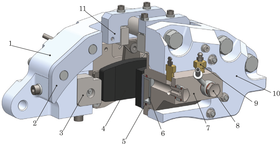
Main components of the caliper assembly: (1) inboard caliper, (2) shim, (3) abutment, (4) brake pad, (5) piston seal, (6) piston, (7) piston module, (8) banjo bolt fitting, (9) bleeding valve, (10) outboard caliper, (11) brake pad pre-load assembly.
A unique property of the caliper is its modularity that allows use of the caliper with a range of different brake disc sizes; it also enables replacing the abutment geometry, or use of a different number of pistons on each side. In the present embodiment, the abutments are designed for standard trailing backplates and each piston module includes two pistons, that is, four pistons in total. For the experiments presented in this paper a grey cast iron ventilated disc was used as shown in Figure 3.
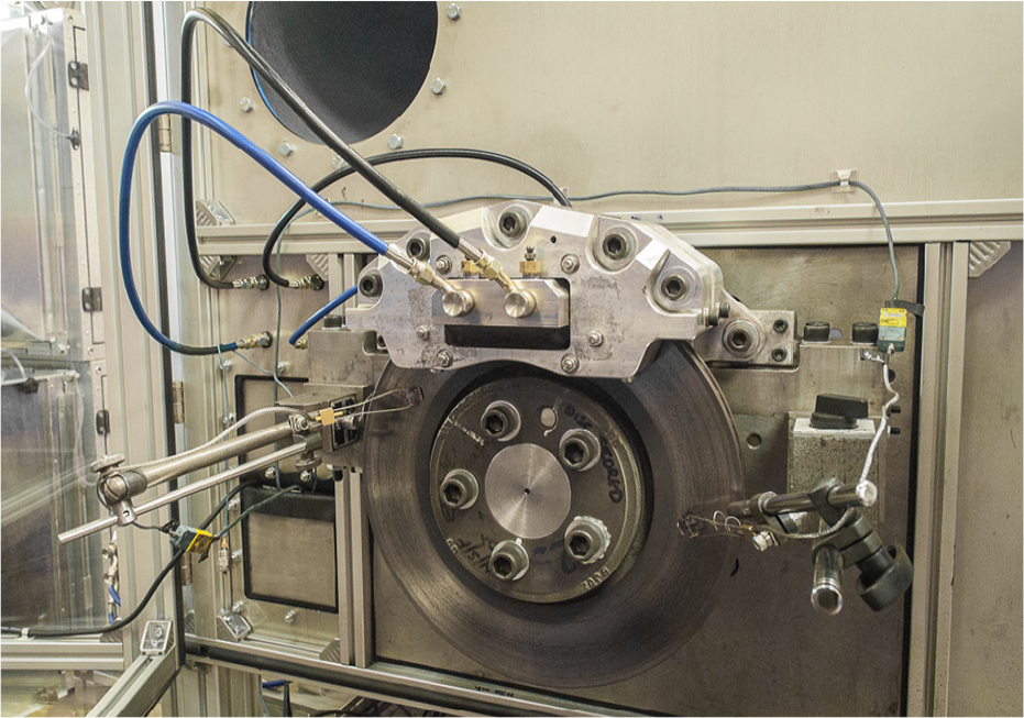
Brake assembly used for squeal experiments consisting of a new prototype caliper and a grey cast iron ventilated disc.
The independent control of the pressure for the leading and trailing side is achieved by hydraulic coupling of opposing piston pairs. This allows control of the leading/trailing pressure ratio (LTPR) as explained in the sectioned view of the caliper assembly through the pistons in Figure 4. By hydraulic coupling of pistons 1 and 3, the leading side of the caliper can be actuated. Similarly, hydraulic coupling of pistons 2 and 4 enables actuation of the trailing side. By changing the LTPR, the CoP position can be moved in the circumferential direction along the pad. For each value of the LTPR, a specific position of CoP can be defined, for example, by using an analytical model. 17
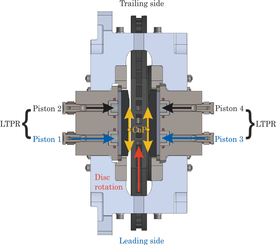
A section view through the piston holes of the new prototype caliper explaining application of unequal piston pressures thereby different leading/trailing pressure ratio (LTPR).
Actuation system
The general system architecture of the new brake test rig is presented in Figure 5. It includes a brake dynamometer powered by 45 kW electric motor, the new prototype brake assembly presented above, a new actuation system with a controller, an operation stand with a computer (PC) and the main data acquisition system (DAQ). The mutual relations between the components are represented by coloured lines. The two-channel pneumatic-hydraulic actuation system was designed to electronically control the piston pressures at the leading and trailing side of the caliper as shown in Figure 6.
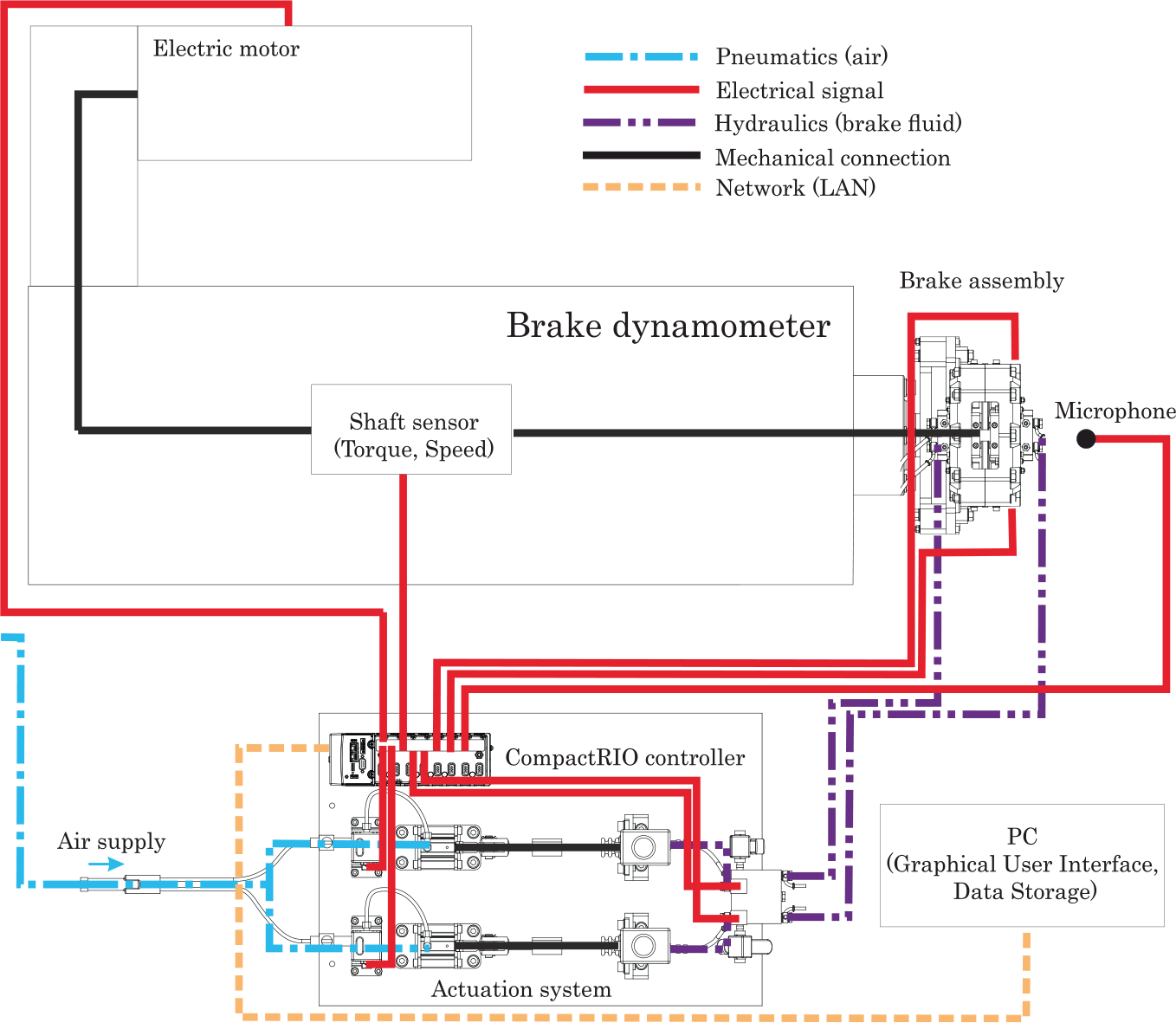
Top view of the brake dynamometer area including schematics of the actuation and DAQ system.
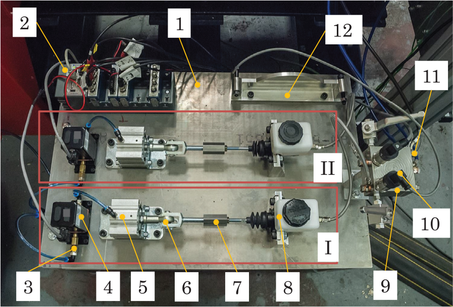
Top view of the new two-channel pneumatic-hydraulic actuation system: (I) leading piston channel, (II) trailing piston channel, (1) table, (2) CompactRIO controller, (3) input air pressure, (4) electro-pneumatic pressure regulator, (5) pneumatic cylinder, (6) rod eye and clevis, (7) adaptor, (8) master cylinder, (9) hydraulic manifold, (10) pressure sensor, (11) output fitting, (12) dummy disc stand.
Each channel of the actuation system includes an electronic air pressure regulator, a single-acting pneumatic piston, a master cylinder and an electronic pressure sensor mounted to the hydraulic manifold. The pressure regulator modulates the input laboratory air supply of 7 bar to the required output pressure. The modulated air pressure controls the output piston force that is transmitted to the rod of the master cylinder, which generates the brake fluid pressure. The brake fluid pressure serves as a process value for the controller. Based on the pressure setpoint, the controller outputs a control signal back to the air pressure regulator. Due to the maximum torque limit of the brake dynamometer, each actuation channel is designed to control the brake fluid pressure in the range 0 to 45 bar.
Control system architecture
A National Instrument™ CompactRIO controller, Figure 6, with a field-programmable gate array (FPGA) module was used to monitor all test rig parameters including microphone signal and was also employed to execute pressure and squeal control algorithms with deterministic response times. 18
Noise characteristics of the brake assembly were monitored using a Behringer ECM8000 measurement condenser microphone. First, the buffered microphone signal is assembled to a waveform and converted from voltage to decibels. Then, the scaled signal is used to compute the power spectrum density using a fast Fourier transformation, where the resulting frequency of interest is limited to interval from 0.9 to 13 kHz. The next operation includes searching for amplitude peaks occuring above 70 dB. Finally, a weighting function applies the A-filtering to the peak amplitude values. If squeal occurs in a frequency bandwith of interest and above a certain amplitude threshold set by the user, the signal is evaluated as a squeal occurrence and the squeal trigger value is changed from 0 to 1.
Pressure and torque control
Principally, the actuation system is capable of two main operational modes: pressure and torque regulation. The first mode uses a single-input single-output (SISO) control scheme along with signals from the pressure transducers as a process value as shown in Figure 7. The pressure transducers used in this work are WIKA type S-20 with measuring range 0 to 60 bar.
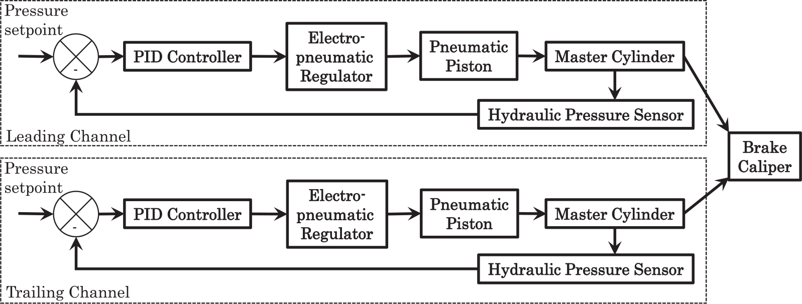
Schematic of the SISO control loop to regulate the brake pressure of the leading and trailing piston channels in the pressure control mode.
Figure 8 shows schematically the torque regulation mode, where the process value is represented by the output value from a torque transducer. The torque transducer is a Torquemaster type TM 213 mounted in the dynamometer shaft with a maximum torque rating of 500 Nm. This also permits measurement of the shaft speed. The torque control mode was designed as a single-input two-outputs (SITO) system, having as its default setting an equal control signal for the leading and trailing channel (LTPR = 1).
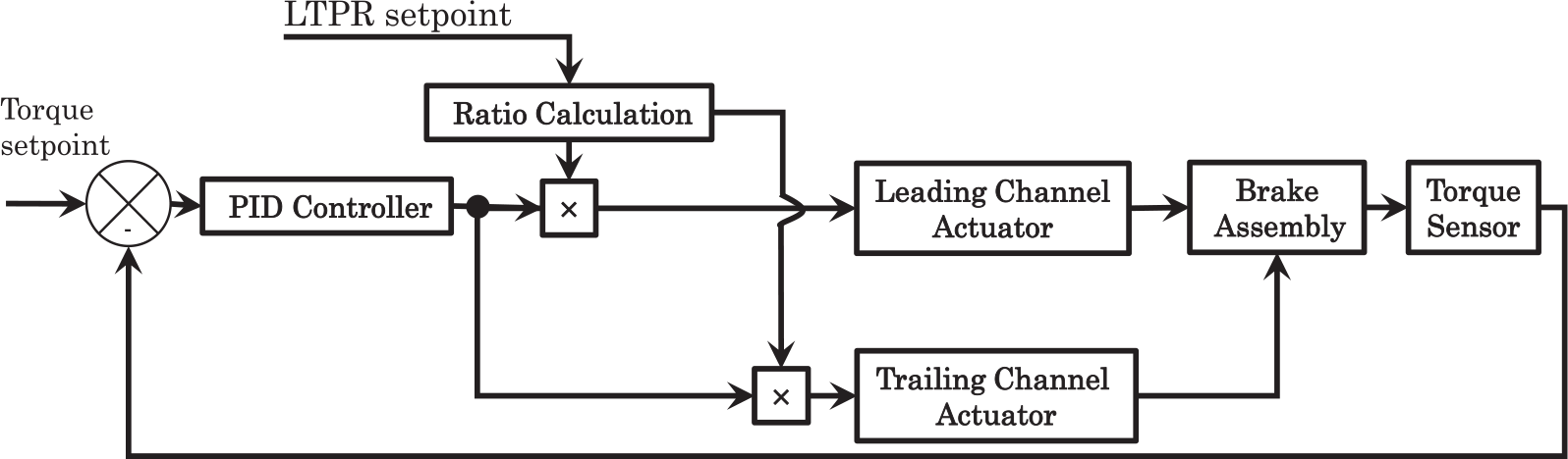
Schematic of the SITO control loop to regulate the brake torque and the LTPR ratio in the torque tracking mode.
Besides the ability to track the brake torque, the torque mode allows the user to change the LTPR by altering the ratio of the two outputs. The main disadvantage of this type of SITO control scheme is that an exact ratio between the two outputs is not closed-loop controlled and principally requires identical hardware components for both actuation channels.
Automatic squeal reduction
The automatic squeal reduction (ASQR) control algorithm developed in this work provides two functions: brake torque tracking and squeal suppression. The brake torque tracking mode was presented in the previous section, here the high-level squeal control algorithm is introduced. The basic principle of the proposed squeal control can be explained by the flowchart in Figure 9.
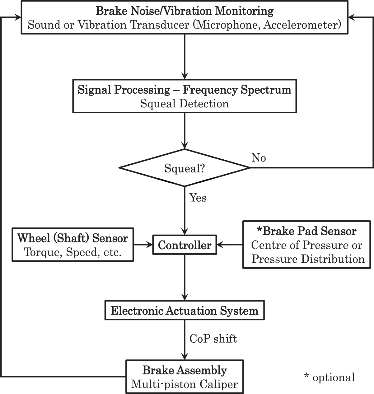
Flowchart showing the basic principle of squeal control.
First, sound from a microphone and/or vibrational signal from an accelerometer is processed to create a frequency spectrum of the signal, which allows the system to find squeal within the required frequency interval and above a certain sound pressure level. If a squeal occurrence is detected, a control algorithm modifies the CoP position at the pad/disc interface using an electronic actuation system while maintaining the value of the process variable. Optionally, the CoP position can be monitored via an embedded pad sensor. In the following description the CoP position is governed by the LTPR value. By connecting an additional controller and squeal detection algorithm to the torque control loop in Figure 8, the schematic of the ASQR control system can be illustrated as in Figure 10.
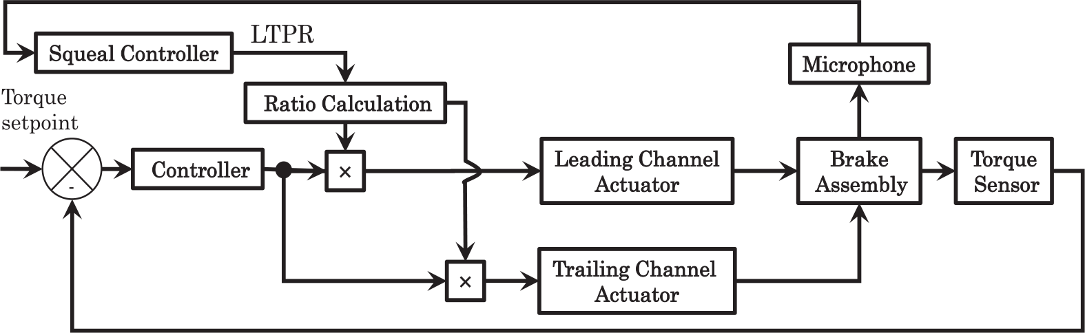
Schematic of the ASQR control loop to regulate the brake torque and squeal in the torque tracking mode.
The ASQR control is based on an on/off control using a simple state-machine to change between particular cases.
18
The sequence of the program is as follows: while the brake torque has a non-zero value, the squeal detection algorithm monitors squeal occurrences, or else terminates the brake application and resets LTPR back to 1. If a squeal event is detected, LTPR is changed to a pre-defined value, for instance
Brake squeal experiments
The new brake test rig described above with the disc as shown in Figure 3 was used to perform a series of experiments to investigate the relation between the leading/trailing pressure ratio (LTPR) and the squeal propensity. The results from these tests were used to determine the LTPR ratios (
Nonuniform pressure
In total, four braking procedures (Test 1, Test 2, Test 3 and Test 4) with the actuation system working in the pressure mode were performed to find potential minima of the squeal occurrence for specific LTPRs. The average pressure for leading and trailing pistons was 5 bar. For Tests 1, 2 and 4 the LTPR was set to 1/9, 1/4, 1/3, 1/2, 1, 2, 3, 4 and 9, whereas for Test 3 the order was reversed to show the possible impact of pad conditioning on the results. The disc speed was set to 30 rpm for the first three tests, whereas for the fourth test the speed was 100 rpm. The temperature of the disc surface was measured with a rubbing thermocouple TC Type 30 and the actual squeal was monitored between 120°C and 150°C. This ensures similar thermal conditions of the disc for each test. The frequency and the minimum amplitude threshold for squeal detection was set to range from 0.9 to 13 kHz and 70 dB(A), respectively.
Figure 11 shows histograms of squeal occurrence as a percentage of the total test time plotted against frequency spectrum at each LTPR for Test 1. The plots clearly mark the unstable frequencies of vibration within the spectrum and demonstrate the influence of the LTPR on the squeal occurrence. It can be observed that for LTPR > 2, the squeal was less frequent. The total relative squeal occurrence as a function of LTPR for all performed tests is plotted in Figure 12.
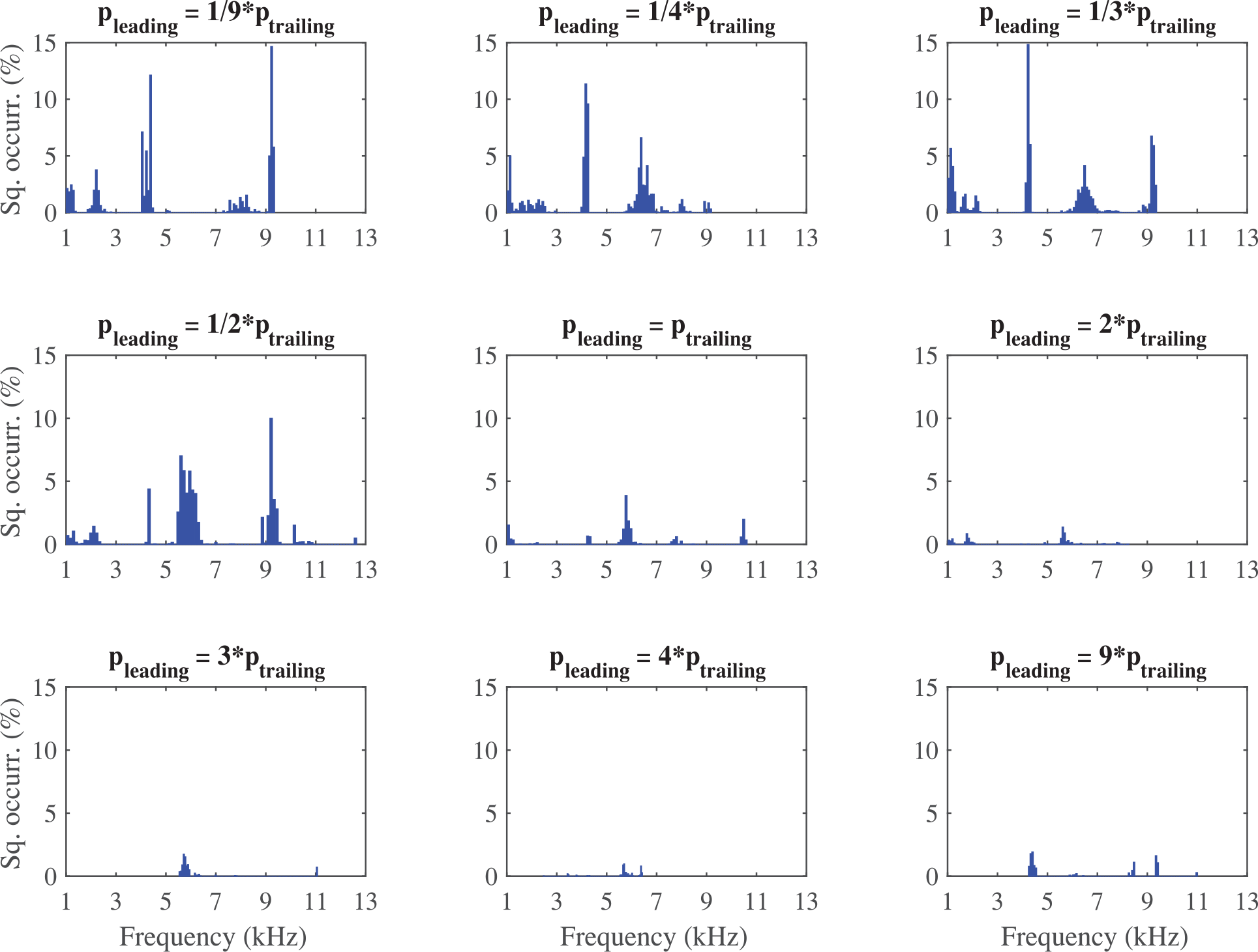
Squeal relative occurrence as a percentage of the total test time plotted against frequency for Test 1 with disc speed of 30 rpm and LTPR = 1/9, 1/4, 1/3, 1/2, 1, 2, 3, 4 and 9.
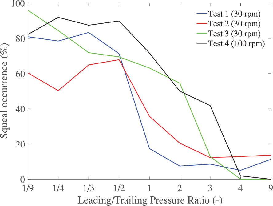
Total relative squeal occurrences for Test 1, 2 and 3 with disc speed of 30 rpm and for Test 4 with disc speed of 100 rpm. The LTPR was set to 1/9, 1/4, 1/3, 1/2, 1, 2, 3, 4 and 9.
All four tests exhibited a similar trend despite the reversed order for Test 3. Evidence of pad conditioning due to increasing LTPR was not observed in this case. For increasing LTPR, the squeal occurrence decreases, having a global minimum for LTPR in the range 3 to 9. A local minimum was observed for CoP on the trailing side for LTPR close to 1/4.
Nonuniform pressure – test cycle
In these experiments, the actuation system was working in the pressure mode following a modified drag braking procedure from the SAE J2521 standard 19 to meet the brake dynamometer operational limits. The standard maximum brake pressure ramp value 30 bar was lowered to 22.5 bar. The disc speeds of 30 and 100 rpm were adopted (roughly corresponding to vehicle velocities of 3 and 10 km/h recommended in SAE J2521). In order to investigate squeal occurrence as a function of the LTPR variations, where LTPR = 1/4, 1/3, 1/2, 1, 2, 3 and 4, the test cycle was designed for each of the leading and trailing channels separately as shown in the example for LTPR = 1/2 in Figure 13.
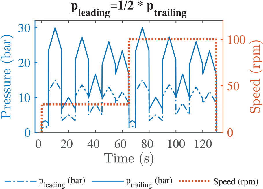
An example of the modified SAE J2521 test procedure to investigate squeal occurrence for LTPR = 1/2.
The pressure ramps were calculated so that the leading/trailing mean pressure at every operational point is the same for all LTPR values. This should prevent significant brake torque variation across all LTPRs and allow a direct comparison of the results. As described in the original SAE J2521, the test cycle was repeated for temperatures from 50°C up to 300°C and from 300°C down to 50°C with increments of 25°C, whereby the whole cycle lasted about 1 h. As a system pre-heat phase, half of the whole cycle (up to 300°C) was carried out, followed by cooling period down to the first measured temperature of 50°C. The experiment was conducted twice (Test 1 and Test 2) using the same disc/pad pair, and each experiment was performed during a single day to minimise the influence of varying environmental conditions on results. Moreover, Test 1 was performed for increasing LTPRs from 1/4 to 4, whereas Test 2 was performed for decreasing LTPRs to compare the effects of possible pad conditioning on the results.
Figure 14 shows histograms of squeal occurrence as a percentage of total test time plotted against frequency spectrum at each LTPR for Test 1. It is clear that the LTPR influences the occurrence of specific frequencies, for example, a low-frequency squeal event of about 1.8 kHz was almost completely eliminated for LTPR = 1/4 and significantly minimised for LTPR = 1/3 and 4. It was also shown that some squeal frequencies remain present even if the LTPR was varied, such as the broad band of squeal frequencies around 8 kHz. The results imply that the potential exists to suppress certain squeal frequencies if an appropriate LTPR as well as suitable noise filtering algorithms are used. Figure 15 depicts the total squeal time in minutes plotted against LTPR for both tests (Test 1 and 2). Although there are small differences in results for the two tests, a general trend can be observed, such as the maximum squeal time occured in the range of LTPR from 1/4 to 1. These curves also demonstrate that the brake tends to be quieter when LTPR > 2, which is in accordance with experiments found in the literature indicating that, as well as a trailing CoP offset, a relatively large leading CoP offset also tends to increase the stability of the brake. 8
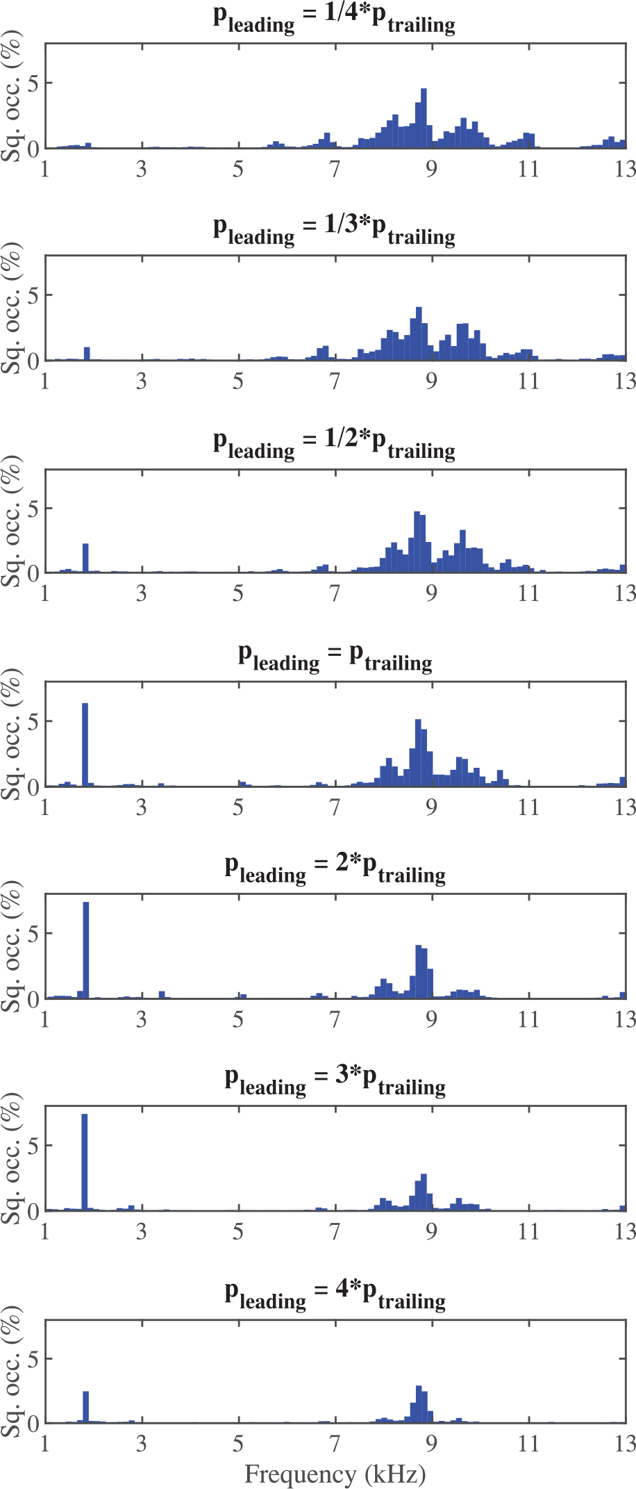
Test 1 – squeal occurrences as a percentage of the total test time plotted against frequency for the modified SAE J2521 drag brake procedure.
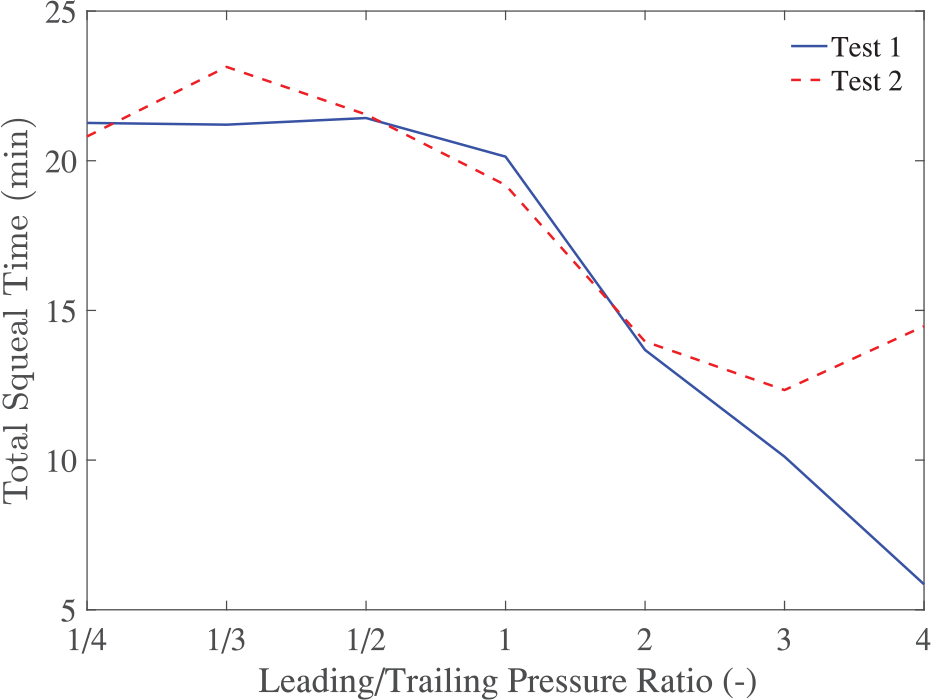
Total squeal time versus leading/trailing pressure ratio (LTPR) for Tests 1 and 2.
LTPR variation
Figure 16 shows an example of how the squeal frequencies were influenced during a slow variation of the LTPR and continuous control of the brake torque in the torque control mode. First a squeal noise at about 12.8 kHz emerges, which gradually fades by varying LTPR, but this generates new squeal events in the range 9 to 10 kHz that are insensitive to further variation of the LTPR. By focusing on a specific squeal frequency band, in this case, for example 8 to 10 kHz or 12 to 13 kHz, a certain LTPR can be identified that can completely eliminate squeal occurrences within this frequency band. This clearly shows that during LTPR change other squeal frequencies can be randomly triggered. However, a more significant focus was on lower squeal frequencies (<5 kHz) because these are more annoying and represent a greater burden on vehicle occupants and the environment. 20
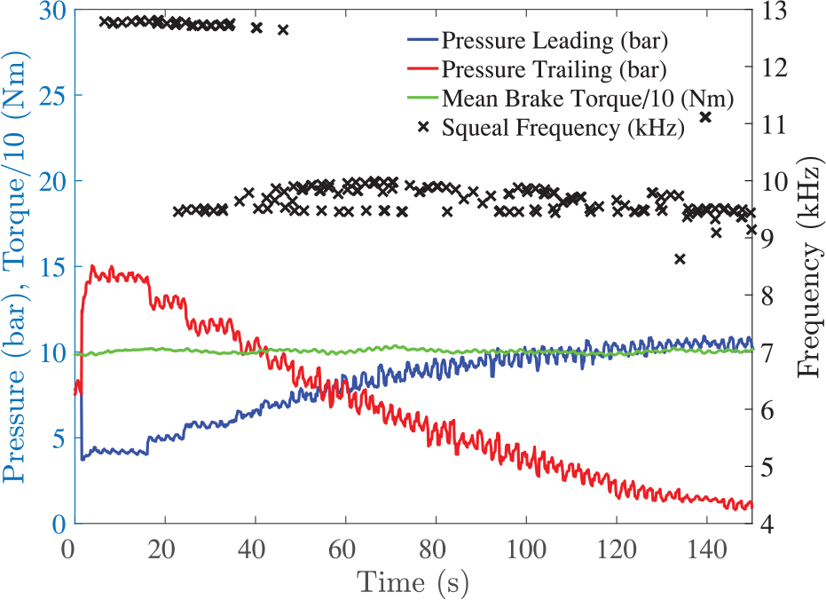
Typical emergence and suppression of squeal frequency during variation of LTPR.
Automatic squeal suppression
Consider now an application of the ASQR system in a semi-automatic mode, that is, the user activates the action of automatic squeal reduction. As an example, Figure 17 depicts an intermittent squeal occurrence of 1.8 kHz that was found for a specific LTPR (in this case LTPR ≈ 3/4) represented by the blue line (leading pressure) and the red line (trailing pressure), respectively. The green line indicates activation of the ASQR mode. In this mode the very first squeal occurrence triggers alteration of the LTPR (to LTPR ≈ 1/4) causing the squeal to disappear. It was observed that after the automatic mode was deactivated and the initial LTPR was recreated in manual mode, the squeal appeared again. 21
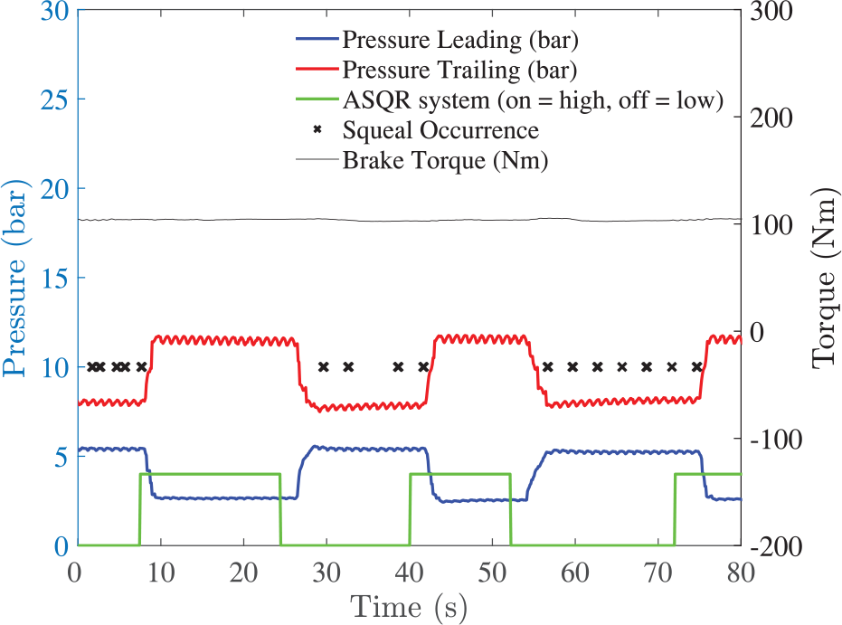
Test demonstrating ability of the automatic squeal reduction (ASQR) system to suppress squeal occurrences in a semi-automatic mode.
In order to demonstrate the fully-automatic mode of the ASQR system during a duty cycle, a simple test schedule containing brake torque ramps of 75, 150, 125 and 100 Nm was designed as shown in Figure 18. Overall, the cycle was repeated for temperatures from 75°C up to 175°C and back down to 75°C, in increments of 25°C. Prior to the test, the brake disc surface was heated to 300°C and cooled down to 75°C. The brake torque, rotational speed and temperature range of the cycle were appropriately chosen to easily recreate low frequency squeal events, such as the one previously detected at 1.8 kHz.
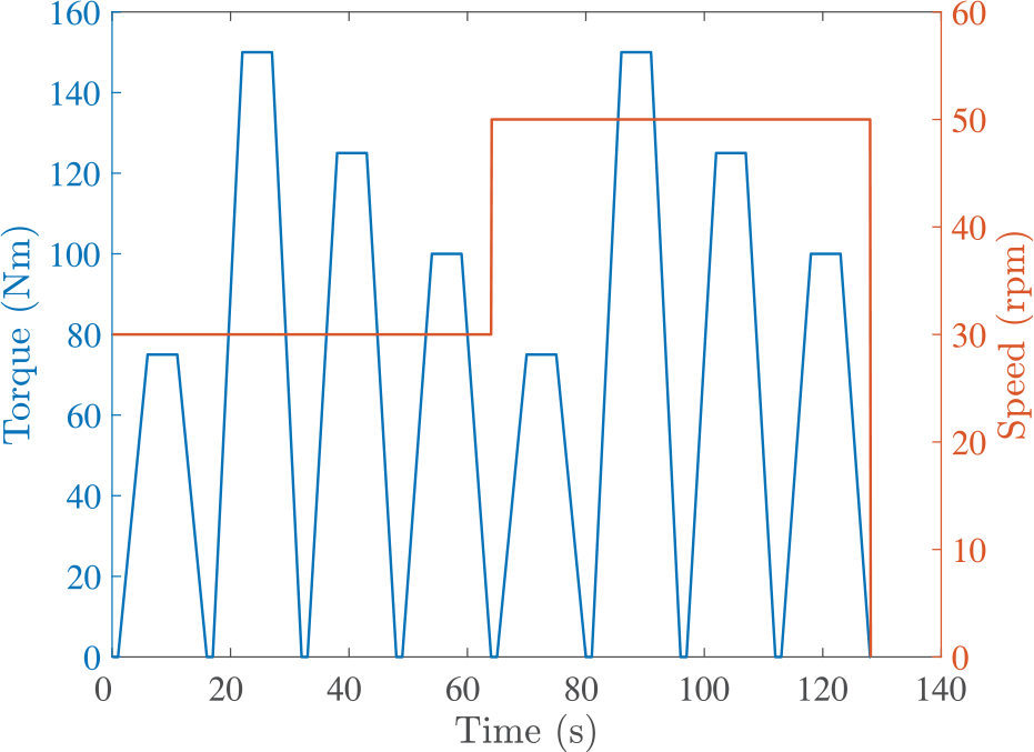
Test cycle for brake torque tracking experiments.
As explained above, certain squeal frequencies occur at every LTPR to some extent. Therefore to simplify the problem, the sound spectrum was filtered to detect only low frequency squeals in the most important range 0.9 to 5 kHz. Moreover, the focus was only on loud squeal, so the amplitude threshold was set to 90 dB(A). When the brake torque command equals zero, which represents a fully released brake pedal, the value of the LTPR is reset to the initial value LTPR = 1. This ensures that the next torque ramp starts with equal pressure acting at all pistons. An illustrative time sequence of squeal suppression is shown in Figure 19, where a squeal noise at about 1.8 kHz emerged (indicated with the black cross symbol). This was readily suppressed by changing the LTPR so that it did not occur until the start of the next brake torque ramp, when the LTPR had been reset again to the initial unity value.
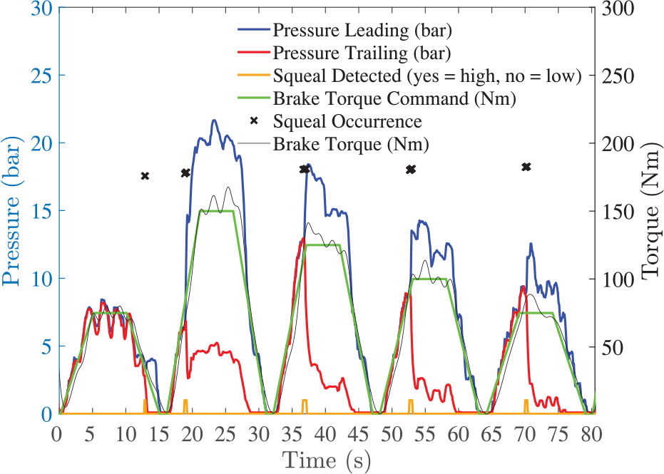
Example of activated fully-automatic ASQR mode during a typical braking torque cycle.
A comparison of squeal occurrence histograms plotted versus the frequency spectrum for a test with deactivated and activated ASQR is shown in Figure 20. The total squeal times for these tests were 71.1 s and 26.1 s, representing a notable reduction of about 63% in favour of the activated ASQR mode.
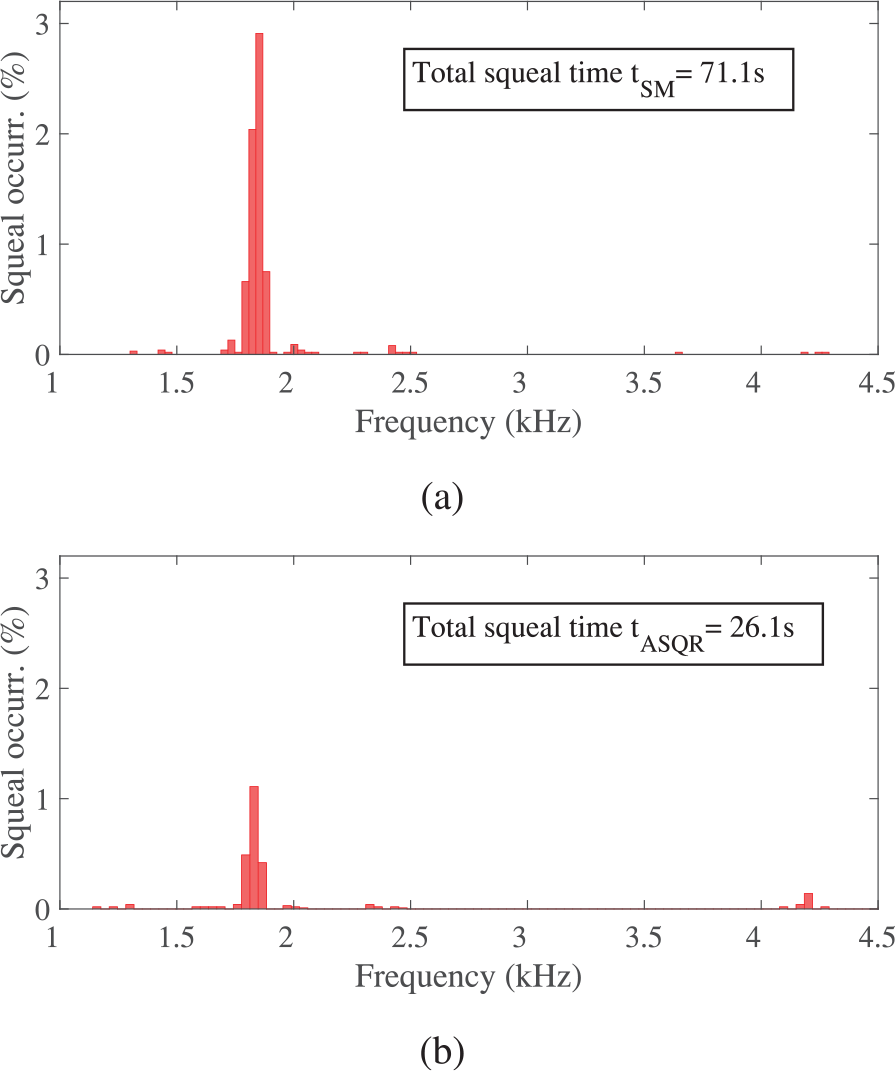
Comparison of squeal occurrence as a percentage of total time versus frequency for: (a) deactivated and (b) activated ASQR mode.
Wear
The impact of the proposed squeal reduction method on brake pad wear is not experimentally studied in this paper. Typically, a pad experiences a lower temperature and a lower wear rate at the leading side, 22 which can result in tapering of the friction material. However, the CoP is for most pads offset to the leading edge increasing wear rate at this side of the pad. 6 These mutually counterbalancing effects can be difficult to predict and a deep understanding requires to conduct numerous experiments. The results could serve as a basis for derivation of an appropriate wear algorithm in the current ASQR module. This modified ASQR module could make a decission based on current pad condition and squeal suppression importance, which would determine the appropriate LTPR from sets of squeal-reducing and wear-reducing LTPR values. In the fully-automatic ASQR mode presented above, this was partly controlled by resetting the LTPR back to 1 after the braking, so the next brake application started with default pressure values.
On-road test
The prototype squeal reduction system is suitable for the laboratory setting where the overall mass and the system complexity do not play a significant role. In order to provide an on-road test, a specific class for test vehicle is required. The test vehicle should be able to accommodate multi-piston calipers and allow modifications on its ABS unit. The caliper would require an additional hydraulic channel and an in-built accelerometer to detect unstable modes of vibration. Alternatively, cabin microphones that are becoming standard vehicle accessory could be used for squeal detection.
Conclusion
It has been demonstrated via brake dynamometer experiments that variation of the leading/trailing pressure ratio (LTPR) influences the squeal frequency spectrum; some low-frequency squeals occured less frequently or disappeared completely for a specific LTPR. The tests showed that LTPR ≥ 4 (large leading offset of the CoP) better minimised the squeal than LTPR < 1 (zero or trailing offset of the CoP). Further tests on LTPR variation were also performed by following a modified SAE J2521 cycle, where LTPR was varied from 1/4 to 4. Here also, the relative occurrence of unstable modes of vibration differed for specific LTPRs. Overall, the minimum total squeal times were found for LTPRs of between 3 to 4.
Furthermore, it has been shown that a simple single-input two-output (SITO) control scheme is appropriate for controlling the ratio between the leading and trailing piston pressures whilst maintaining constant brake torque.
It has also been demonstrated that the new ASQR system in a fully automatic mode successfully suppressed squeal in most cases if a relatively narrow squeal band of interest was defined, such as 0.9 to 5 kHz, and the LTPR was altered from 1 to 4 after squeal detection. Due to a sophisticated control architecture the brake torque was only minimally influenced during this process. The performance of the ASQR system has been demonstrated for a newly developed test cycle where it minimised the total time of low-frequency squeal occurrence by 63% which is a significant reduction.
Future work will investigate the possibility to test the proposed squeal suppression system in a brake control system such as ABS that is already present on today’s vehicles. In addition, a more advanced squeal algorithm for monitoring the actual condition of the pad and its wear will be studied. Such an integrated control system represents an enabling technology to encourage implementation of the squeal reduction method presented here.
Footnotes
Declaration of conflicting interests
The author(s) declared no potential conflicts of interest with respect to the research, authorship, and/or publication of this article.
Funding
The author(s) received no financial support for the research, authorship, and/or publication of this article.