
Abstract
Active vibration control of automotive drivetrains must be developed to compensate for the backlash of gears because it causes undesired responses. In addition, an engine used as an actuator has a constraint which makes the control periods longer and time-varying, resulting in deterioration of the control performance. The contribution of this study is to cope with all the issues described above, backlash and the control period constraint, simultaneously. First, a basic experimental device, which simplifies an actual vehicle to focus on the effect due to backlash, is demonstrated. In the device, the control period constraint, which is equivalent to that of an engine, is reproduced by a digital signal processor. To reduce an adverse effect due to the extension of the control period, the sampled-data controller, which does not require discretization in its implementation, is employed. In this paper, predictive processing using the servo-type sampled-data controller is proposed to compensate for the phase delay of the control input caused by the time-varying control period. In addition, a control mode switching technique included in the prediction suppresses undesired responses due to backlash. Finally, control experiments verify the effectiveness of the control system.
Keywords
Introduction
Active damping of vibrations of automotive drivetrains remains a challenge to improve the riding comfort and driving performance of automobiles. In particular, when the engine torque changes suddenly (tip-in and tip-out), backlash of differential gears degrades the vibration control performance. Specifically, the shock torque, which is generated when the gear runs freely and collides in backlash, increases the vibration amplitude. To compensate for effects on controls due to backlash, example studies include the use of the descriptive function method, 1 the application of a neural network, 2 a fractional order proportional-integral-derivative (PID) controller, 3 a proposal for an adaptive fuzzy type H∞ control, 4 the application of a H∞ control, 5 and the modeling of backlash as a disturbance. 6 Regarding the control of automobile drivetrains with backlash, previous studies include an investigation of several nonlinear controllers based on PID control 7 and a proposal for a switching technique with linear-quadratic regulator (LQR) controllers. 8 In particular, many outcomes are related to model predictive control (MPC).9–14 These are broadly considered to be effective techniques. A mode-switching-based active control algorithm including the sliding mode technique and PID control has been investigated by simulation studies. 15
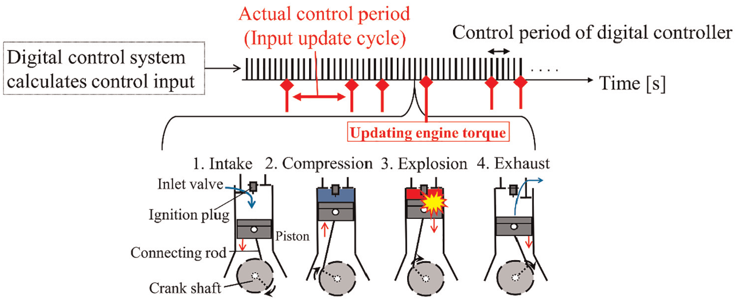
In addition to the backlash problem, the limitations in the control period of actuators used for active damping of automotive drivetrains present additional problems. An example of such an actuator is the engine, 16 in which the generated torque corresponds to the control input. An engine cannot update the control input at the timing synchronized with that of a digital controller. This is due to the relationship shown in Figure 1 between the mechanism to update engine torque and the digital control cycles. An engine requires a series of processes (exhaust, intake, compression, explosion, and expansion) to update the generated torque value. In other words, the control input can only be updated at the moment when an explosion occurs in a combustion chamber and a crankshaft rotates by 180°. When an engine is used as an actuator, the intervals of the explosions, which depend on the engine speed, are the actual control periods. The two essential problems caused by this actuator constraint are
Compared to the first resonant modes to be damped, the actual control periods are relatively long. Hence, a digital controller must be used (implemented) with the extended control periods, resulting in increased adverse effects of discrete approximation errors.
The actual control periods are time-varying. This delays the phase of the control inputs, which can be generated by the actuator as command signals from a controller.
Although few studies have focused on the control period constraints with respect to active damping of automotive drivetrains, several notable studies have been proposed. The delay with the realization of a torque was modeled by the Pade approximation for controller design. 17 Modeling of an engine with a fixed maximal delay and the H∞ controller design in continuous-time domain ensured the phase margin to cope with the mechanism to update engine torque. 18 In addition, predictive controllers have been proposed to compensate for the engine delay,16,19,20 and their effectiveness has been experimentally validated.
Limitation of the control period due to the mechanism generating engine torque.
In the previous works, however, it is not taken into account that the control periods of the actuator are made longer by problem (A), indicating that discrete approximation errors with traditional discretization are not compensated for. In addition, the undesired response due to backlash, such as an overshoot, remains although it must be reduced. It means that compensation is not considered while backlash is traversed.
Compared to the previous studies, the present research addresses all the issues, the adverse effect due to backlash, and the control period constraints (A) and (B), simultaneously. The contribution of this study for active damping of automotive drivetrains is the combination of compensations for the following three issues:
(C1) Backlash causes the undesired response, such as an overshoot, under the condition where a driving force suddenly changes (tip-in and tip-out).
(C2) The control periods are relatively long compared to the period of the first resonant mode to be damped, corresponding to (A).
(C3) The control periods are variable depending on time, corresponding to (B).
In this study, a basic experimental device, which simplifies an actual vehicle to focus on the influence due to backlash while reproducing only the basic structure of the automotive drive system, is used to verify the control system.
In our previous study, 21 an approach to apply the sampled-data control to the extension of the control period (C2) was proposed. The sampled-data controller can explicitly consider responses between sample points because the design process does not require discrete approximations to implement. Hence, the controller implemented with a long control period prevents performance degradation due to discrete approximation errors even under the constraints. In the present paper, based on the previous study, a method for coping with the time-varying control periods (C3) is proposed. Because the time-varying control period causes phase delay of the control input actually updated by the actuator, predictive processing using the sampled-data controller is necessary. Specifically, a control input for the next step is predicted, and the predicted value is approximately used to compensate for the maximal phase delay for a command signal from the controller. In addition, a simple control mode switching algorithm to compensate for backlash is proposed, focusing on the adverse effects that occur when driving forces suddenly change. The compensation is performed while backlash is traversed, and it suppresses both the overshoot and the oscillations by reducing the shock of a collision. Finally, experiments using the basic experimental device verify effectiveness of the proposed control system.
Basic experimental device
Mechanical structure of the experimental device
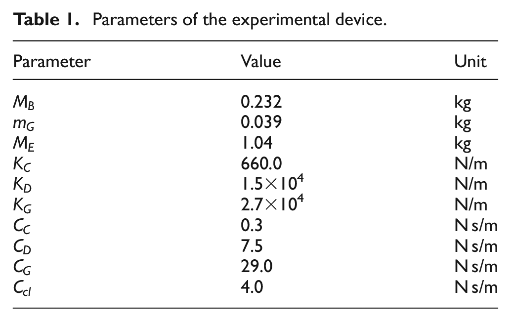
The basic experimental device, which simplifies an actual vehicle to focus on the influence due to backlash while reproducing only the basic structure of the automotive drive system, is used as a controlled object. Figure 2(a) and (b) show the dynamical model and the real mechanism, respectively. Table 1 shows the device specifications. This is a three-degrees-of-freedom system, in which three weights (
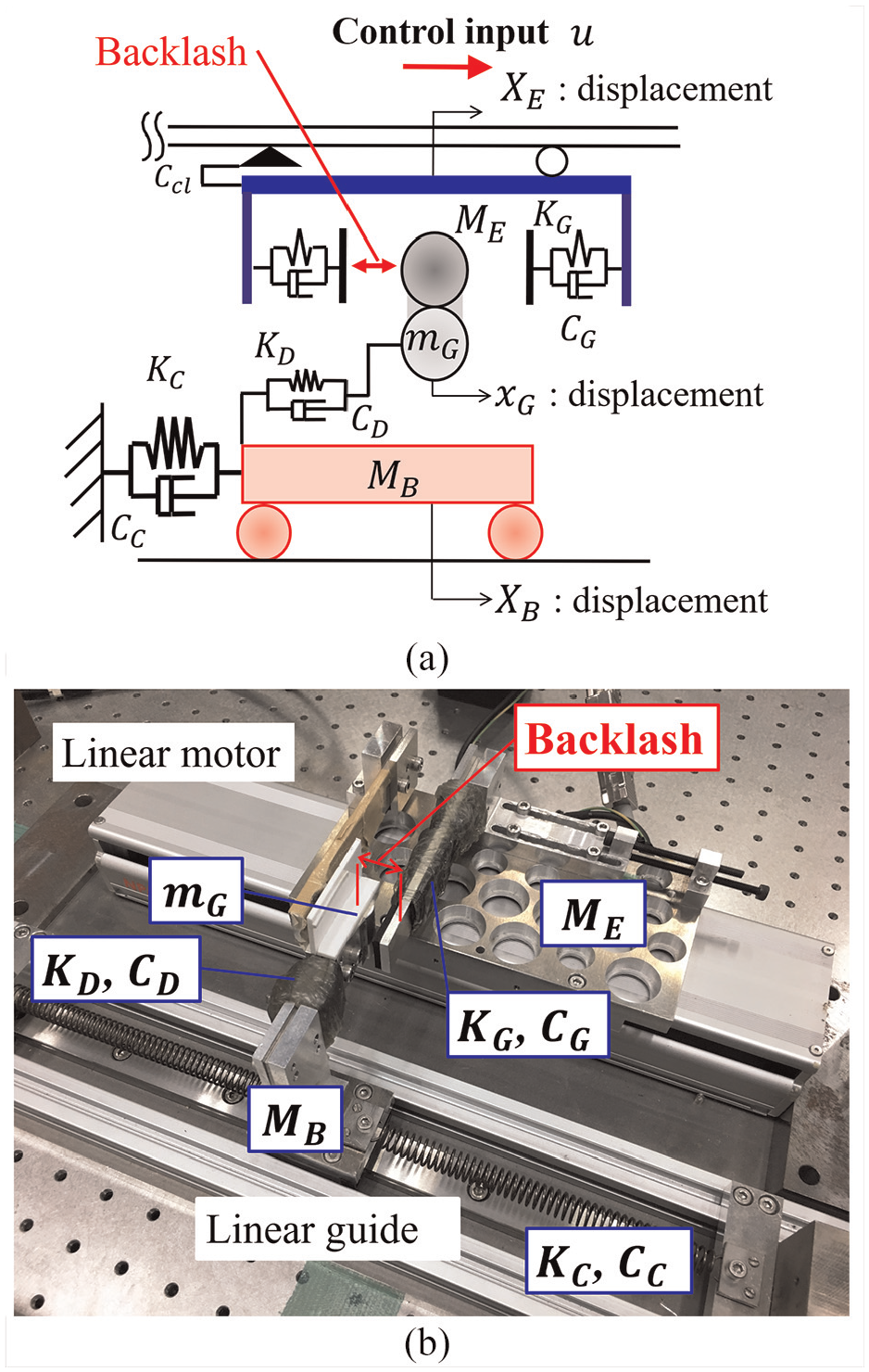
Basic experimental device: (a) dynamical model of the experimental device and (b) real mechanism.
Parameters of the experimental device.
Setting the control period constraint
The experimental device shown in Figure 2(b) uses a linear motor as an actuator. Because it is difficult to construct the real mechanism of an engine shown in Figure 1, only the control period constraint, which is equivalent to that of an engine, is given to the motor by a program in a digital signal processor (DSP). Figure 3(a) shows the conceptual closed-loop system of the control experiment. Even though the controller in the DSP can calculate the control inputs with short and constant periods, the program in the same DSP restricts the periods of actually updating the control inputs. It makes the actual control period longer and time-varying. As a result, a thrust updated with the constrained periods drives the motor while the control input intended by the controller cannot be realized as is.
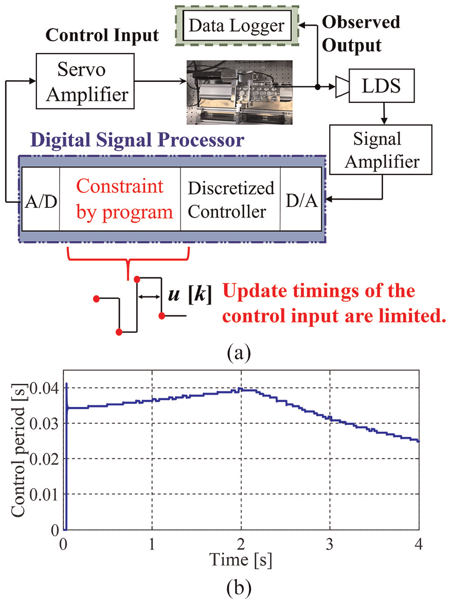
Experimental system using laser displacement sensor (LDS): (a) diagram of the closed-loop system and (b) time history of the control period, which is long and time-varying.
The actual (time-varying) control periods, as shown in Figure 3(b), are produced in the DSP as a constraint. The periods like that in Figure 3(b) were used and were approximately recorded in the control experiment demonstrated in the section “Control experiments.” According to these control periods, the constraint program in the DSP holds the control input (motor thrust) to the same value, regardless of the new command from the controller. In Figure 3(b), the frequency to update the control input varies from approximately six to nine times the natural frequency (4 Hz) to be damped. Consequently, both the target conditions (C2) and (C3) are prepared.
Modeling
Since the experimental device has nonlinearities such as the backlash, the linearized model is necessary to design a sampled-data controller. The state equation and the output equation of the system are then derived as


Each coefficient matrix and the state variables are described as
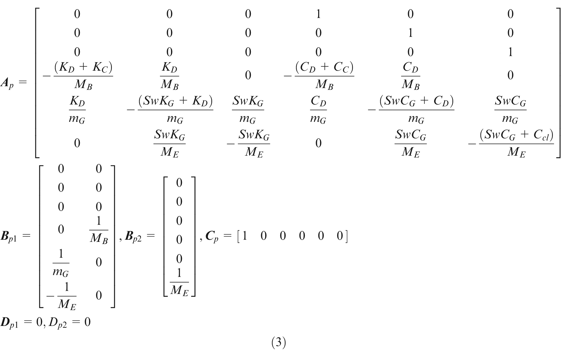
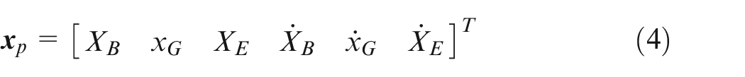
In equations (1) and (2), u is the motor thrust (control input), and
The time-varying linear state equation of the experimental device with the backlash and other nonlinear characteristics is also described in Yonezawa et al. 22
Compensation for extended control periods
According to the previous study, 21 the sampled-data H2 controller25–27 is applied to the plant to maintain the controller’s performance even with the extended control period (C2). In the sampled-data control, involving no discrete approximations with the design allows responses between sampling points to be explicitly considered. Therefore, the implementation of the controller with a sampling period as long as possible prevents performance degradation due to the long intervals taken to update the control inputs. The designed controller is used in the predictive processing demonstrated in the next chapter.
Figure 4(a) shows a generalized plant used to design the controller.
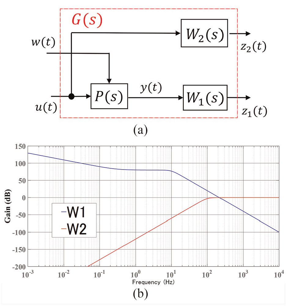
Design of the sampled-data controller: (a) generalized plant used to design the controller and (b) gain of the frequency weighting functions.
This study uses a weighting function

The cut-off frequency
(P1) The transient vibration is sufficiently reduced.
(P2) The controlled variable follows the target signal with fewer steady errors.
The good control performance indicated above cannot be obtained by only tuning
The parameters of
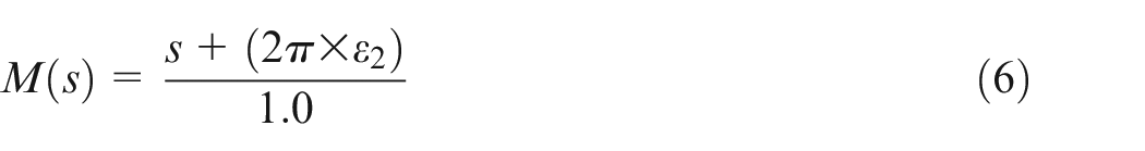
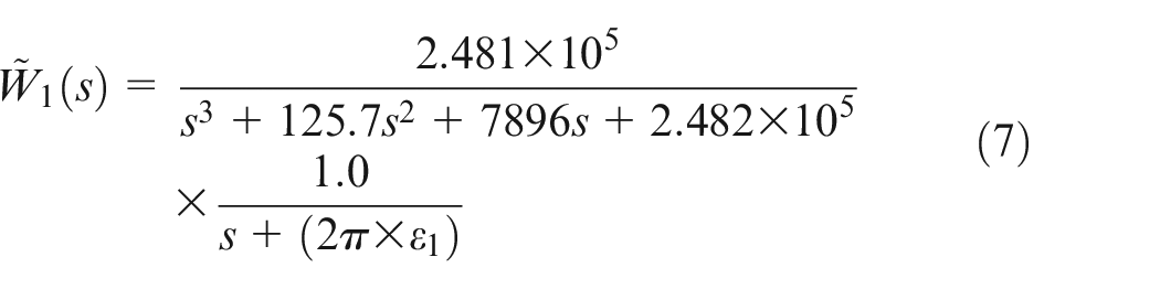
The low-pass filter in the first fraction of equation (7) is introduced to limit the controlled frequency band of the vehicle body vibration
To reduce the steady errors with respect to the step target signal, it is necessary to make the approximate integrator
The multiplication of the approximate integrator in equation (7) by
The high-pass filter
Compensation for time-varying control periods
Phase delay of the control input
Figure 5 shows the control simulation result. This is an enlarged graph of the control inputs where a sampled-data controller with a fixed control period is directly applied to the plant, which has a time-varying control period. The black and red lines indicate the command signal from the controller (hereafter the instructed input) and the control input actually driving the actuator (hereafter the actual input), respectively.
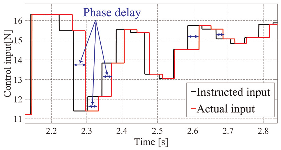
Phase difference between instructed inputs from the controller and inputs actually updated by the actuator.
The effect due to the time-varying control period (C3) appears in the form of a phase delay in the control input. As seen from Figure 5, the phase difference between the instructed and actual inputs is an adverse effect to control systems. The phase of the actual input (red line) is always delayed. In the second half of the control period, an actual input is updated as the instructed input of nearly one whole past step. This produces the most adverse effect on control systems.
One step ahead prediction with backlash compensation
In this study, predictive processing for one step ahead compensates for the delay. This compensates for the most adverse case, where an actual input is updated in the second half of the control period. To improve the control performance, an actual input should follow the instructed input calculated at the step nearest to the actual update time. Consequently, in the second half of the control period, the predicted input one step ahead is approximately used as the instruction.
Here, a conceptual scheme of the proposed control system is described. Figure 6 outlines the compensation method, assuming that the current time is
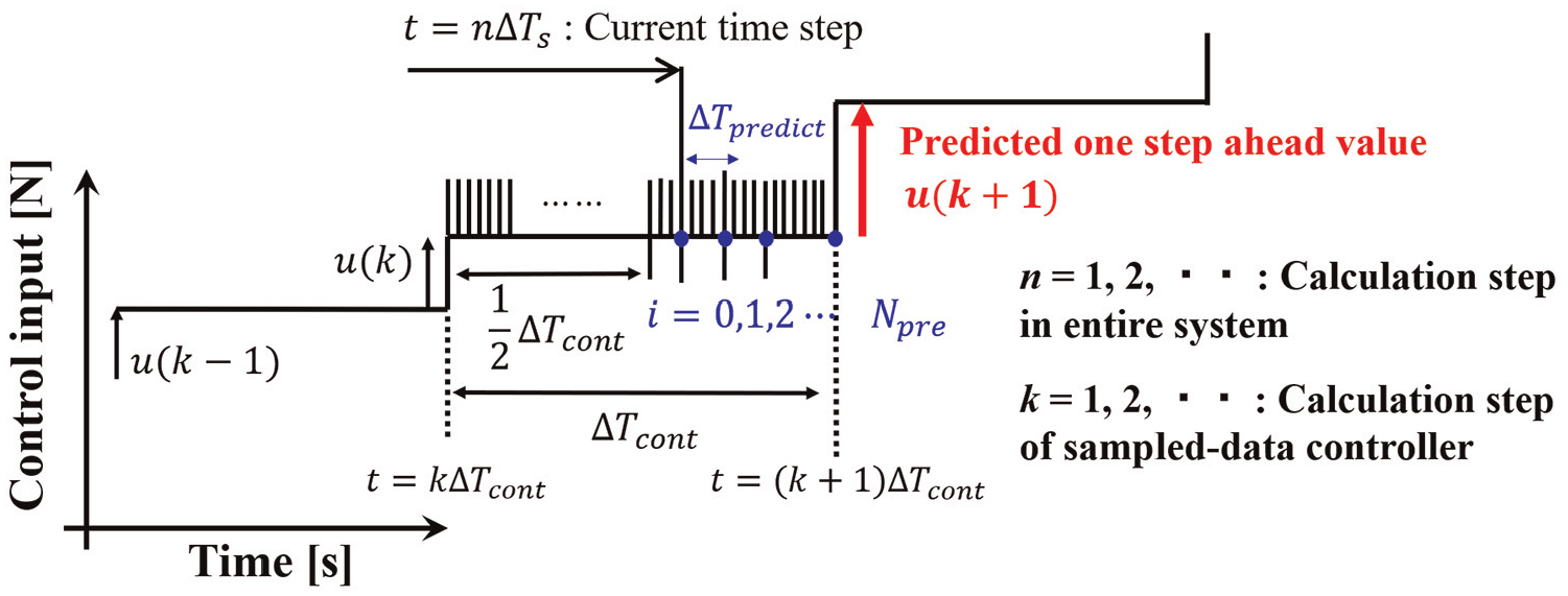
Conceptual scheme of one step ahead prediction to compensate for the phase delay.
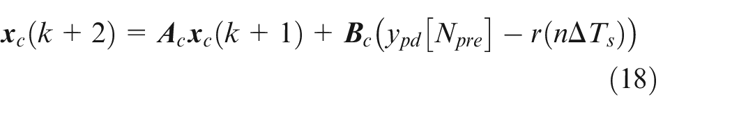
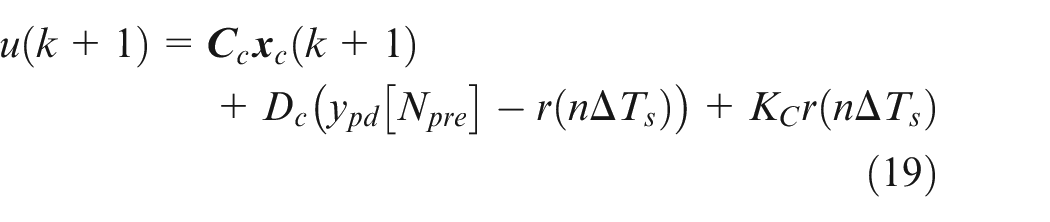
Specifically, a simulation of the plant from
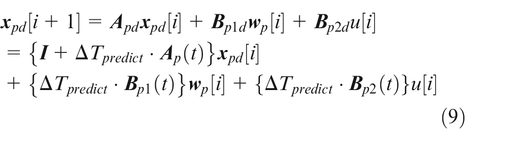
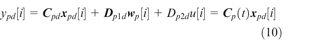
where

Using the time-varying linear state equation of the experimental device with nonlinearities such as the backlash,
22
each coefficient matrix in equations (9) and (10) is obtained online. It is also used for the state estimation demonstrated later. In equations (9) and (10),
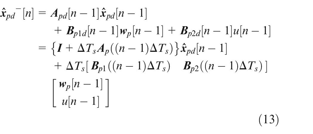
The simulation requires initial conditions, which correspond to the state quantities
This study attaches relatively more importance to robustness against uncertainties of the real device than compensation for accuracy of the sensor. Therefore, the covariance matrices were tuned to be a relatively large “q” and a small “r.” With respect to the vibration during the mechanical contact occurring in the backlash, this tuning policy is aimed at making the contribution of the observed output to the estimation result larger than that of the estimation process equations (13) and (14) using only the plant model in the Kalman filter. In addition,
(Step 1). A priori estimate
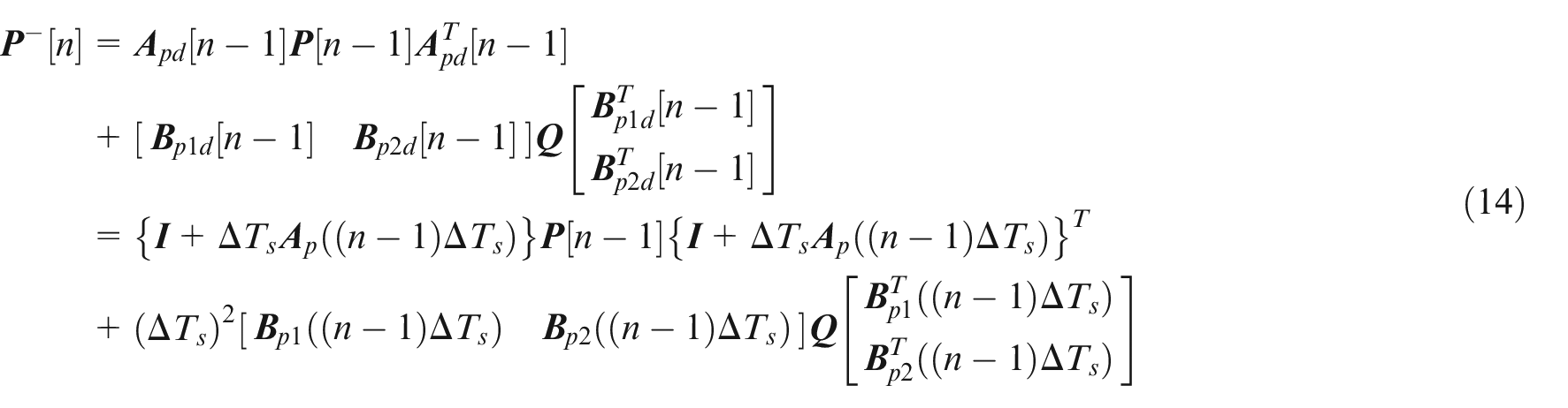
(Step 2). A priori covariance matrix
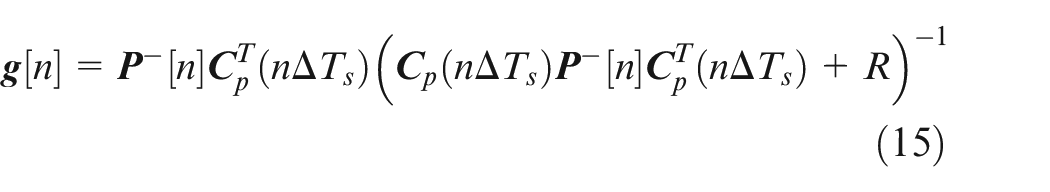
(Step 3). Kalman gain
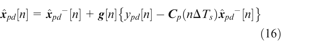
(Step 4). An estimated state quantity
(Step 5). A posteriori covariance matrix

Specifically, q and r were determined as
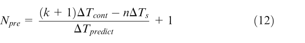
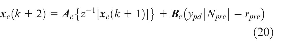
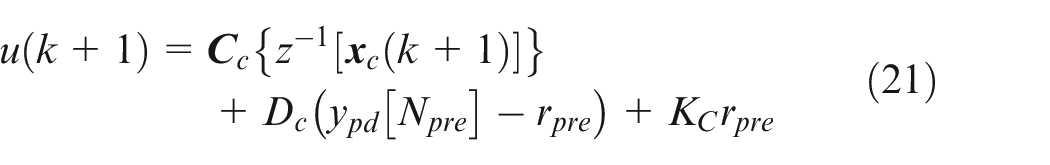
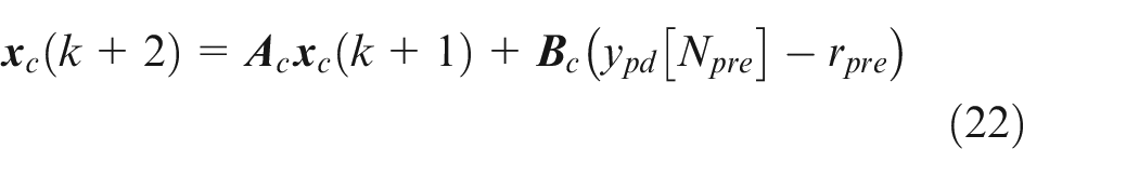
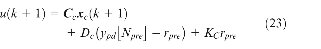
To predict the control input at
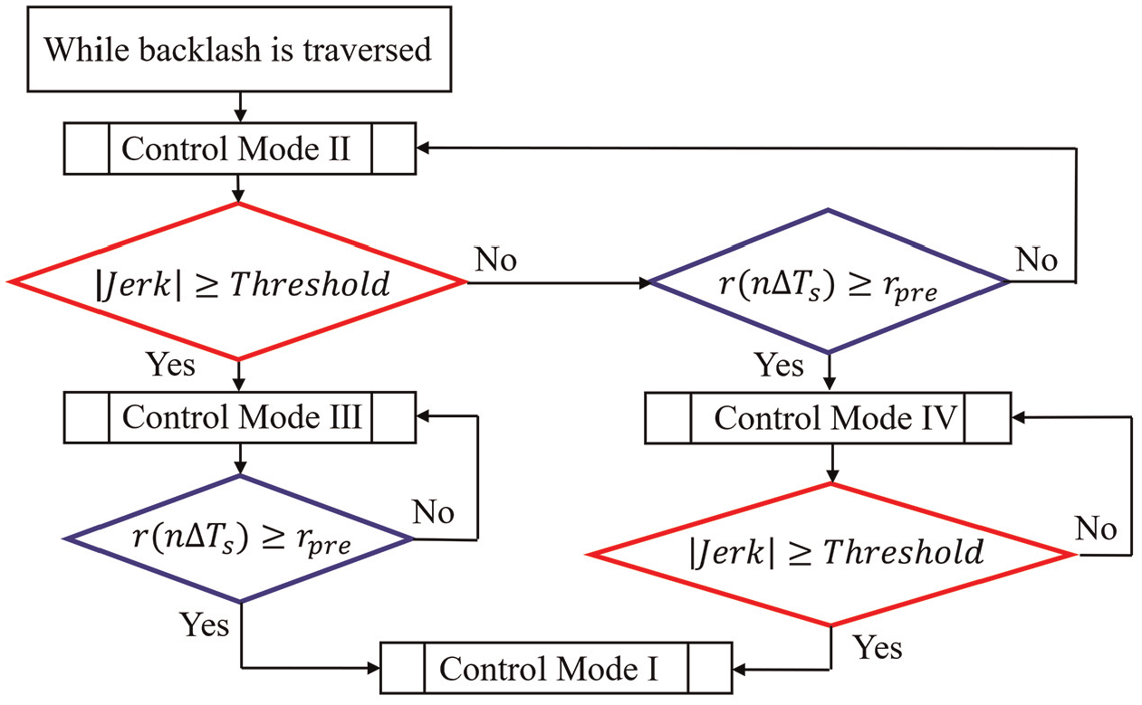
Flow chart of switching control modes.
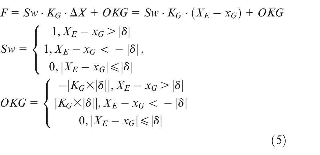
Control Mode I is the normal control that operates during the mechanical contact in backlash. Control Mode II performs the compensation while backlash is traversed. Here, switching the target signal to a small positive value
Control Mode I:
Control Mode II:
Control Mode III:
Control Mode IV:
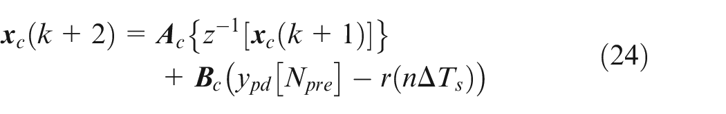
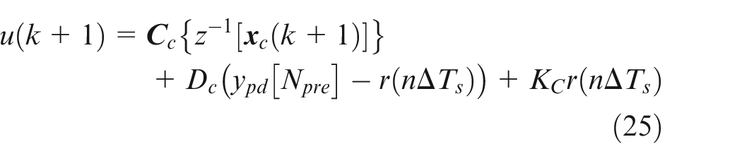
Figure 7 indicates the conditions to switch each control mode. In particular, to identify mechanical contact in backlash, a jerk, which is obtained by differentiating the acceleration of the vehicle body with respect to time, is used as the threshold condition.
Control experiments
Verification of fixed long control period
First, a sampled-data controller is verified for the plant with the fixed control period constraint (only (C2)).
21
The long control period of (C2) is determined as
Figure 8 shows the experimental results under the constraint of the fixed control period (only (C2)). The upper and lower graphs show the time history waveforms of the vehicle body vibration and the control input, respectively. The blue line is the response without control and the green line is the target signal to be followed. The red and black lines indicate the results obtained by a sampled-data controller and a continuous-time controller, respectively. Specifically, the solid lines mean that controllers are verified for the long control period (Legend: “Sd-H2 long” and “C-H2 long”), while the results for the short period are shown in the dotted lines (Legend: “Sd-H2 short” and “C-H2 short”).
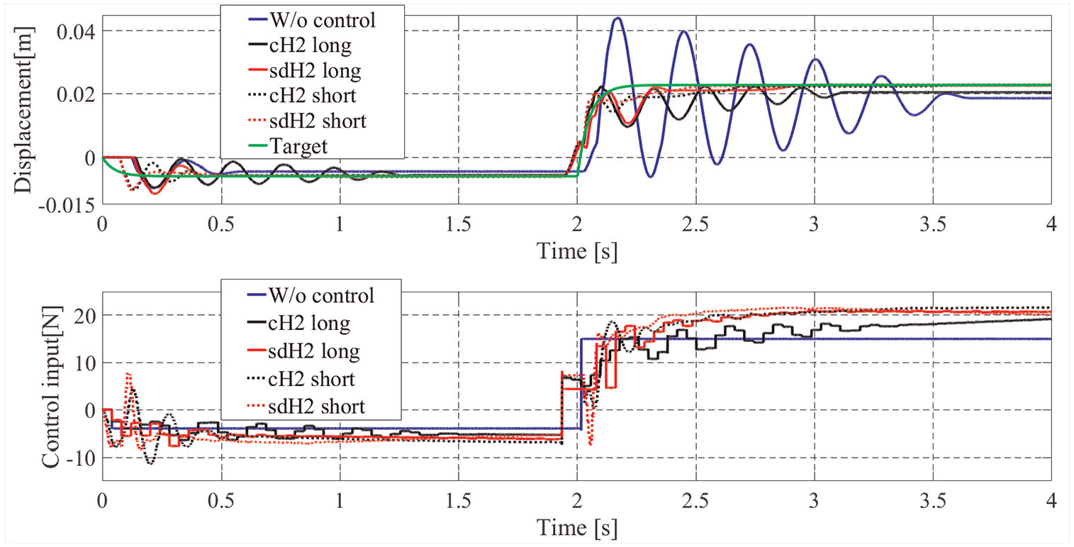
Displacement and control input obtained by the control experiments when the control period is fixed.
Verification of time-varying long control period
Next, the experimental results under the condition where the control period is long (C2) and time-varying (C3) are presented. Regarding the proposed control system,
Figure 9 shows the experimental results under the constraints (C2) and (C3). As one of the worst cases, the magenta line indicates the response without compensation (predictive processing) for the time-varying period. The yellow line shows the result without compensation for backlash, although the control period constraints (C2) and (C3) are dealt with. The red line indicates the control result from the proposed method, which simultaneously compensates for all the control period constraints (C2) and (C3), and backlash.
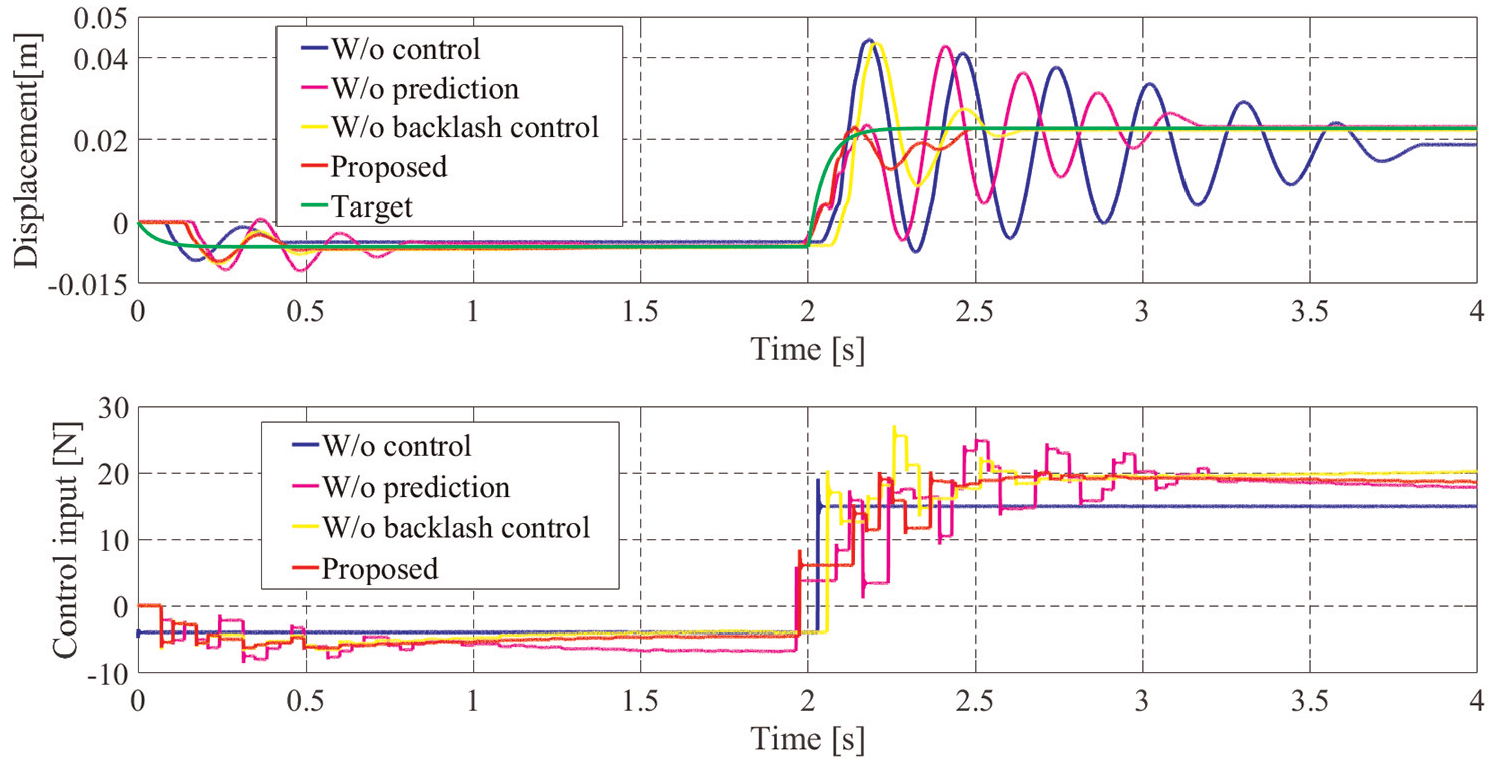
Displacement and control input obtained by the control experiments when the control period is time-varying.
Discussion
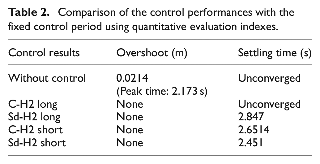
Figure 8 demonstrates the improvement by the sampled-data controller for the control period constraint (C2). Both the sampled-data H2 controller and the continuous-time H2 controller perform the good performances with sufficiently short control period. However, the continuous-time controller deteriorates in performance with the long control period due to the effect of discrete approximation errors. On the other hand, the sampled-data controller maintains the high damping performance even under the constraint. Table 2 expresses the performance obtained by each control system as quantitative evaluation indices. It also demonstrates the above effectiveness of the sampled-data controller against the long control period. “None” in Table 2 means that the overshoot with respect to the steady value of the target signal did not occur. The settling time is the time that the output takes to achieve and remain within a specified error range ±5% around the steady value of the target signal. Regarding the control system that could not settle the output within the range, it is expressed as “Unconverged” in Table 2. More detailed considerations on the performance differences between the two controllers can be found in the literature. 21
Comparison of the control performances with the fixed control period using quantitative evaluation indexes.
For the constraints (C2) and (C3), Figure 9 shows good control performance, demonstrating the effectiveness of the proposed approach described in the section “Compensation for time-varying control periods.” Specifically, the transient vibration that occurs after backlash is traversed (after 2 s) is greatly reduced with the compensation for the time-varying period (the red line) compared to that without compensation (the magenta line). This improvement indicates that the predicted input for the next step is appropriate to compensate for the phase delay. Figure 10 is an enlarged graph of the control inputs obtained from the proposed method. The variation in switching interval of the instructed input and the elimination of the phase delay suggest that the predicted inputs can be given as instructions, as shown by the arrows. These phase compensations immediately after backlash is traversed contribute to the vibration improvement. However, only the predictive processing may have difficulty in ensuring robustness of the damping performance because the compensation for the update timing at near
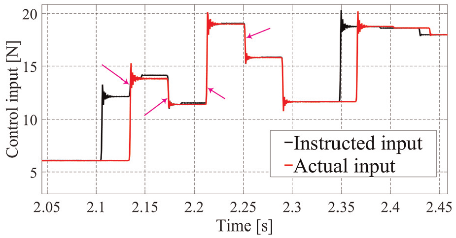
Enlarged graph of the control inputs obtained from the proposed control system.
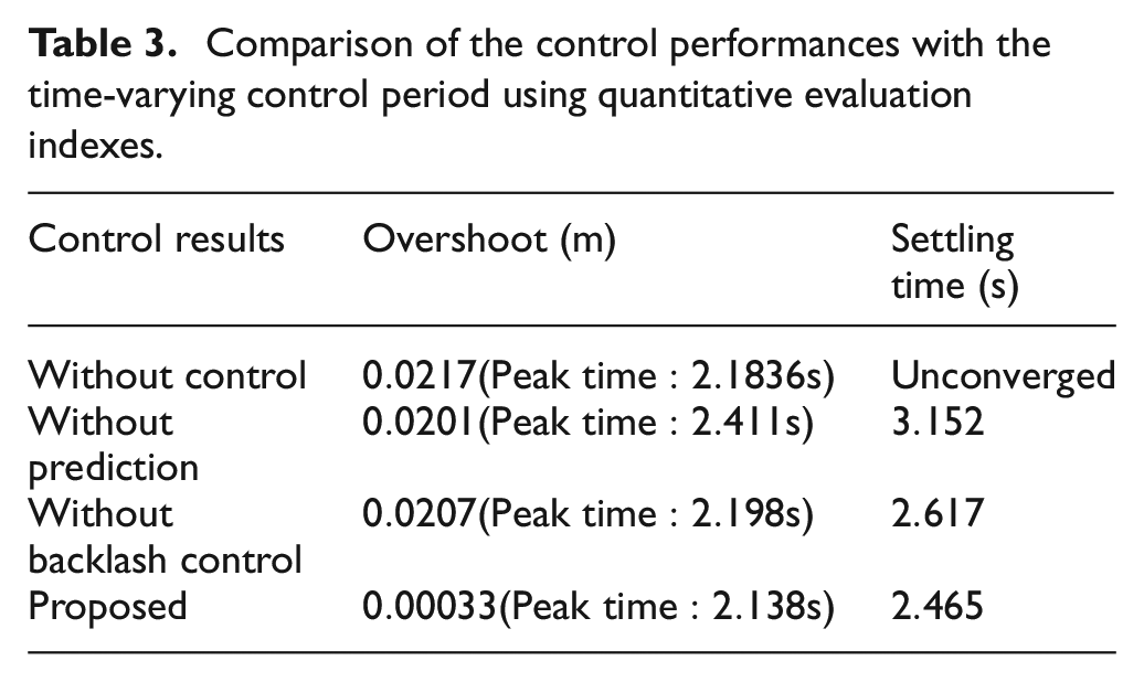
Next, the improvement thanks to backlash compensation is evaluated from a comparison between the red and yellow lines in Figure 9. Without the control mode switching (the yellow line), overshooting occurs just after the target signal rises due to backlash. When the target signal suddenly changes at 2 s, because an uncontrollable time zone due to backlash causes control errors to accumulate, the controller calculates unnecessarily large control inputs, resulting in a collision and a large shock force. On the other hand, with the compensation for backlash (the red line), a high control performance to suppress the overshooting is obtained. From the control input, it is demonstrated that backlash is reduced beforehand during the dead time. Furthermore, the anti-windup prevents excessive control inputs, and backlash is gently traversed.
The above control performances shown in Figure 9 are also summarized in Table 3 as the quantitative evaluation indices. Table 3 quantitatively confirms the effectiveness of the proposed control system, which consists all of the sample-data controller, the predictive processing for the time-varying effect, and the backlash compensation.
Comparison of the control performances with the time-varying control period using quantitative evaluation indexes.
Regarding
While the plant model used for the Kalman filter has some uncertainties such as frictional characteristics, it can mostly reproduce the macro behavior of the experimental device such as the low-frequency vibration that should be controlled. Therefore, even if the covariance matrices are tuned to be a small “q” and a large “r,” the control performance may not remarkably deteriorate.
Conclusion
This study proposed an active vibration control method for automotive drivetrains with backlash considering the constraint on control periods. First, the basic experimental device, which simplifies an actual vehicle to focus on the backlash while reproducing only the basic phenomena of the drivetrain, was described. In experiments, a motor with the control period constraint, which is equivalent to that of an engine, makes control periods longer and time-varying. To compensate for the constraint, predictive processing using the servo-type sampled-data controller was presented. Furthermore, the control mode switching technique included in the prediction suppressed the undesired responses due to backlash. Finally, the proposed approach was verified experimentally, demonstrating its high control performance.
In the future, the practicality of the proposed method needs to be verified by applying it to real vehicle drivetrains. In addition, we will investigate the sensitivity of the control performance to the tuning of the control system parameters in more detail. Furthermore, studies on the enhancement of robustness of the control system against various verification conditions and controller tuning, which are more quantitative and theoretical, are also necessary.
Footnotes
Declaration of conflicting interests
The author(s) declared no potential conflicts of interest with respect to the research, authorship, and/or publication of this article.
Funding
The author(s) disclosed receipt of the following financial support for the research, authorship, and/or publication of this article: A part of this work was supported by Japan Society for the Promotion of Science (JSPS) KAKENHI (Grant Number JP 20J11084).