
Abstract
The primary function of the piston compression ring is to seal the combustion chamber from the bottom end of the engine. As a result, its conformance to the cylinder liner surface is of prime importance. This close-contact contiguity results in increased friction, making this contact conjunction responsible for a significant proportion of energy losses. The frictional losses can be as much as 2–6% of the expended fuel energy, which is quite significant for such a diminutive contact. Under these conditions, the geometrical profile, the surface topography and the inertial properties of the ring assume significant importance. The paper presents an integrated mixed-hydrodynamic analysis of the compression ring–cylinder liner contact with multi-parameter optimisation, based on the use of a genetic algorithm. The multi-objective functionality includes minimisation of the parasitic energy loss, reduction in the incidence of asperity level interactions as well as minimisation of the ring mass. Both cold running engine conditions and hot running engine conditions in line with the New European Drive Cycle were considered. Hitherto, such an approach has not been reported in the literature.
Keywords
Introduction
An improvement in the fuel efficiency, a reduction in the emissions and refinement of noise and vibrations are the key objectives in powertrain optimisation. In recent decades, the main development concept has been to achieve a compact powertrain with a high output power-to-weight ratio. 1 Furthermore, the powertrain performance is not judged merely by these objectives and costs but also by issues of durability and reliability. Therefore, the design and development of a powertrain results in a multi-variate problem, often with conflicting key objectives. For example, the choice of materials can often meet the requirements for the durability of the system, but lightweight structures fail to guard against a plethora of noise and vibration concerns.2–5 Moreover, lightweight compact designs, which mitigate errant dynamic losses, can result in reduced contact clearances, thus promoting undue friction. 6 Therefore, significant design challenges arise with contradictory outcomes for key design objectives, indicating the necessity for embedded optimisation within the design analysis and development.
The internal combustion engine will remain a major source of propulsion for the foreseeable future, and particularly for much of the land transport sector. The key objectives of modern engine design are mitigating the harmful emissions, 7 as well as constantly improving the fuel efficiency, while retaining a high output power-to-weight ratio. In this quest, the reduction in frictional power losses is of prime concern. The frictional losses of an engine account for 20% of all its total losses, and the contribution from the piston–cylinder system is nearly half of these. 8 The share of these losses due to the top compression ring is invariably between 30% and 40%, mainly because of its designed tight fitment in order to comply with its primary function in sealing the combustion chamber.8,9 Therefore, overall, the frictional power loss from the top compression ring can account for 3–6% of the expended fuel, which is quite significant for such a light and compact component. 10 A decrease in the ring tension tends to reduce these frictional losses, 11 but at the expense of increased elastodynamic behaviour of the ring, leading to gas leakage, blowby and power loss. 12 Therefore, an optimisation process within a multi-parameter numerical analysis is essential for an optimal design.
The reciprocating nature of the piston ring–cylinder liner contact results in a broad range of lubrication regimes experienced under transient cyclic conditions. The mechanism of friction generation is usually dominated by the hydrodynamic viscous shear in the intake and exhaust strokes and at the midspan piston position throughout the four-stroke cycle. However, at piston reversals, particularly in the compression and power strokes, the lubrication regime tends to be mixed or boundary lubrication regime. Friction is generated through combined Poiseuille shear and direct contact of asperities on the counterface surfaces.13–17 Therefore, a model to account for the interaction of the roughness of contiguous surfaces should be used. This is usually based on the work of Greenwood and Tripp. 18 This model has been frequently used for the case of the piston ring–liner conjunction.14,17,19–21 Morris et al. 21 also incorporated the effect of the ring contact face geometry, which significantly affects the entrainment of lubricant into the contact; thus, it may be regarded as an important parameter.
In recent years, a trend in minimising the in-cycle frictional losses has been to reduce the lubricant viscosity 22 on account of the dominant Couette friction throughout most of the piston cycle. However, this can have adverse effects in the higher-loaded counterformal contacts in the engine, such as the cam–follower contact subjected to elastohydrodynamic lubrication with thin films. 23 Therefore, it is not advisable to include the lubricant rheology in localised optimisation analysis, in this case for the compression ring–cylinder liner conjunction.
In this paper a multi-variable multi-objective optimisation approach is presented to maximise the efficiency and the surface durability and to minimise the mass of the compression ring by considering the variations in the ring geometry and the ring tension. The analysis is based on the solution of Reynolds equation, combined with boundary interactions using the Greenwood–Tripp 18 model. The multi-variable multi-objective optimisation approach is based on the CAMEO software from AVL. 24 A series of manoeuvres are used in the analysis, based on both the cold steady-state part and the hot steady-state part of the New European Drive Cycle. 25 The results clearly demonstrate the contradictory outcomes in the aforementioned conjunctional performance metrics, highlighting the need for the embedded optimisation process. Such an approach has not hitherto been reported in the literature.
Theoretical formulation
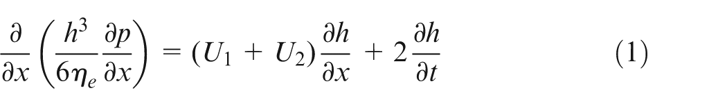
As the ring length exceeds its contact face-width by a factor of at least 30, a simplified one- dimensional analysis can be undertaken, as reported by Haddad and Tian. 26 This simplification assumes full peripheral conformance of the ring to the surface of a liner of right circular cylindrical shape. In practice, the liner has out-of-round dimensions, and the ring undergoes a global elastic modal behaviour in its radial plane as well as some degree of out-of-plane twist and rotation. Representative analyses for these features have been provided by Tian et al., 27 Baker et al. 28 and Rahmani et al. 29 However, inclusion of these features integrated with a multi-parameter optimisation is computationally prohibitive. Thus, the form of Reynolds equation becomes
Various studies which have not considered localised deformation of the contiguous surfaces have produced excellent conformance to experimentally measured frictional losses in the compression ring–cylinder line conjunction.13,20,30 This assumption is particularly valid in the current case as the Ni–Cr–Mo coating applied to the cylinder liner has a high modulus of elasticity (400 GPa). Therefore, only very small elastic deformations of the surface should be expected. For similar materials and engine conditions, Morris et al. 21 calculated the maximum deformation to be δ = 0.011 μm, which is negligible in comparison with the minimum film thickness presented in the current study. Hwu and Weng 31 investigated a diesel engine which has a peak in-cylinder pressure that is twice that studied in the current paper. Also the elastic modulus used in that study was 100 GPa for the cylinder liner which is significantly lower than that in the current text. In that case, the effect of elastic deformation was worthy of consideration.
Thus, the lubricant film thickness can be stated as

where the transient minimum film thickness h0(t) and the ring face profile S(x) vary in the axial direction x. S(x) defines the parabolic ring shape through its crown height c and the off-centre distance xS according to (Figure 1)
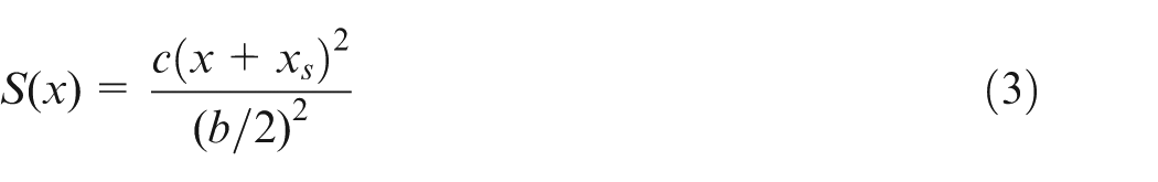
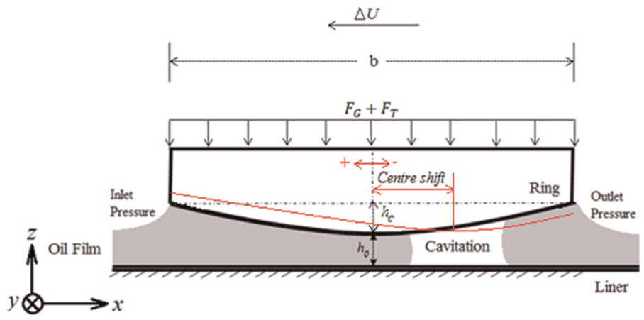
Geometry of the ring contact face.
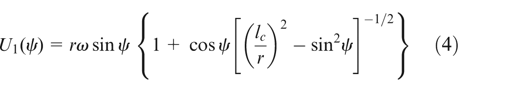
The bore is stationary and, therefore, U2 = 0, whereas the ring is assumed to move without any axial flutter or twisting motion. It is therefore assumed that the sliding speed of the ring is that of the piston and can be written as 1
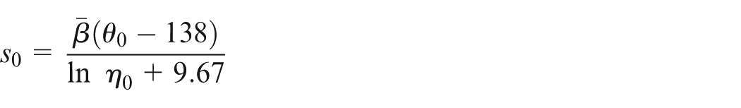
The effective viscosity of lubricant is determined using the Roelands 32 equation (the liner is assumed to be the effective film temperature 33 )
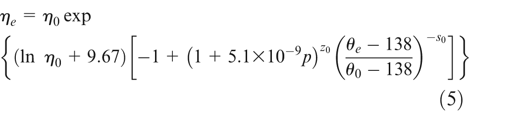
where
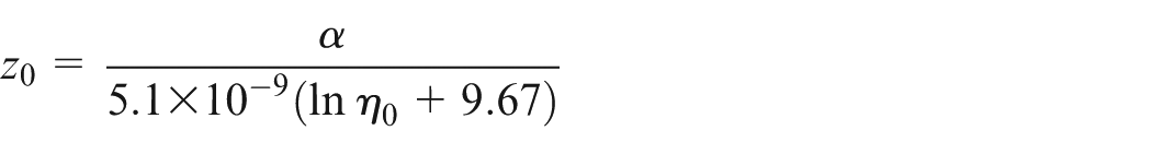
and
Boundary conditions
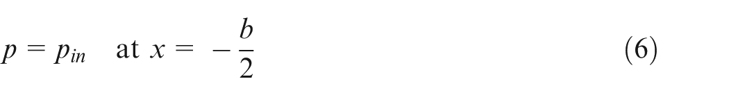
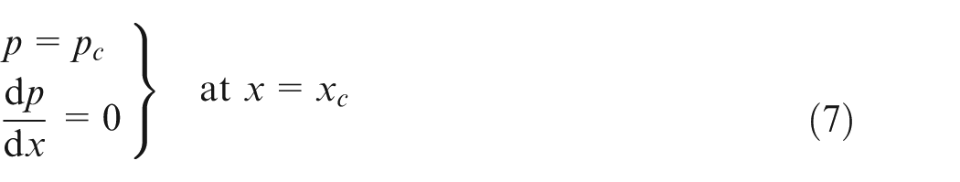
A fully flooded inlet is assumed. The inlet pressure pin at the edge of the ring is the combustion chamber pressure in the piston upstroke and the crank case pressure in the downstroke. The Swift 34 –Stieber 35 exit boundary conditions, which are also referred to as the Reynolds exit boundary conditions, are employed in the current analysis. Therefore, the boundary conditions are
Friction
Viscous friction is due to the viscous shear of the lubricant film over the apparent contact area as given by
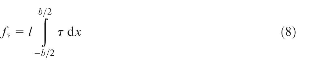
where l = 2πr0. The average hydrodynamic shear stress is 6
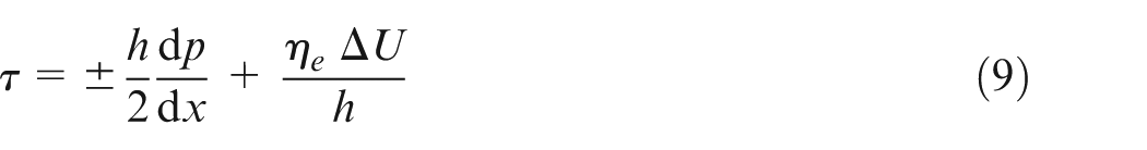
where the positive sign is used for the ring and the negative sign for the liner. Therefore, the absolute value of the shear stress remains the same for both surfaces.
On, and in the vicinity of, ring reversals, the lubricant film can no longer fully support the load; therefore, some degree of boundary interactions ensues. The boundary friction is obtained as 18

It is assumed that a thin adsorbed layer of lubricant resides at the asperity summits and acts in accord with the non-Newtonian Eyring shear stress τ0. Additionally, the boundary shear strength of the surfaces contributes to friction. This is denoted by ς. For surfaces with a layer of ferrous oxide, 23 ς = 0.17. The asperity contact area Aa and the share Wa of the contact load carried by the asperities are functions of the typical geometry of the asperities and their assumed distribution. For a Gaussian distribution, these are 18

and
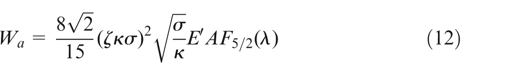
respectively, where E′ is the equivalent plane strain elastic modulus for the counterface surfaces, ζθσ is the roughness parameter, 36 A is the apparent area of contact which is equal to the area of the ring face and F2 and F5/2 are statistical functions. The overall friction is

The power loss at any crank angle becomes

The total cyclic energy loss El due to friction is the integral of the power loss with respect to time and is given by
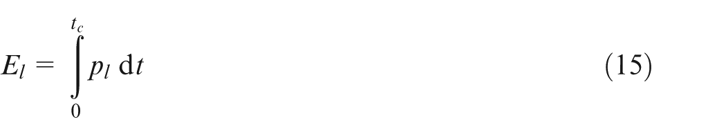
where tc is the time taken for a four-stroke engine cycle.
Method of solution
At any instant of time, the pressure distribution is obtained by solving equations (1) to (5) using the finite difference approach. The convergence criterion for this iterative solution is
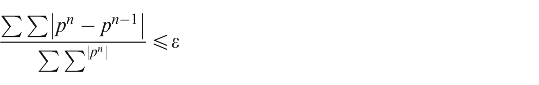
where ε≤ 1 × 10⁻⁵.
The contact load-carrying capacity is determined from addition of the lubricant contact reactions: Wh = ∫p dAh, where Ah = A – Aa, and the load Wa carried by asperity interactions. 37 The carried load must equate to the load F applied to the conjunction, which is due to the combined ring tension and chamber pressure acting behind the inner rim of the ring (Figure 1), both of which press the ring contact face onto the liner surface; 38 thus,
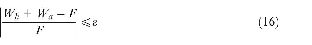
where29,33ε = 1 × 10⁻³. If this criterion is unfulfilled, the instantaneous minimum clearance h0 is altered and the calculation procedure is repeated according to

where
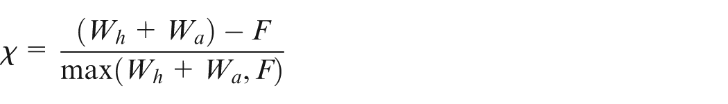
and the superscript k denotes the iteration step. A damping coefficient β of 0.005 is employed to improve the rate of load convergence, while avoiding numerical instability in the convergence process.
When the convergence criterion is met, the crank angle ψ is advanced, the new sliding velocity of the ring is obtained and the entire calculation procedure is repeated.
Optimisation approach
Because of the multi-variate nature of the problem, a multi-objective approach based on a genetic algorithm is performed. The CAMEO software from AVL is used for this purpose. 24
As the first step in this approach, a set of simulations covering different conditions with the desired range is undertaken. Different considered parameters and objectives are used. In total, four variables and three objectives are considered in the current study, as highlighted in the seventh section.
The second step after determining the variables is the construction of an optimisation model, which consists of a polynomial fitting (extrapolation) of a set of objectives against the determined variables. This enables the search for an optimum point to be made over the entire range of variables. The adherence of the polynomial fit is an important factor for the accuracy of the results. A combination of the first step and the second step provides the possibility of carrying out an optimisation task, using a discrete number of simulations. In this case, 10,001 simulation runs of the model were carried out and covered the entire working envelope. Alternatively, real-time simulations coupled with the optimisation algorithm are required, which is generally very time consuming.
Results and discussion
Engine specifications
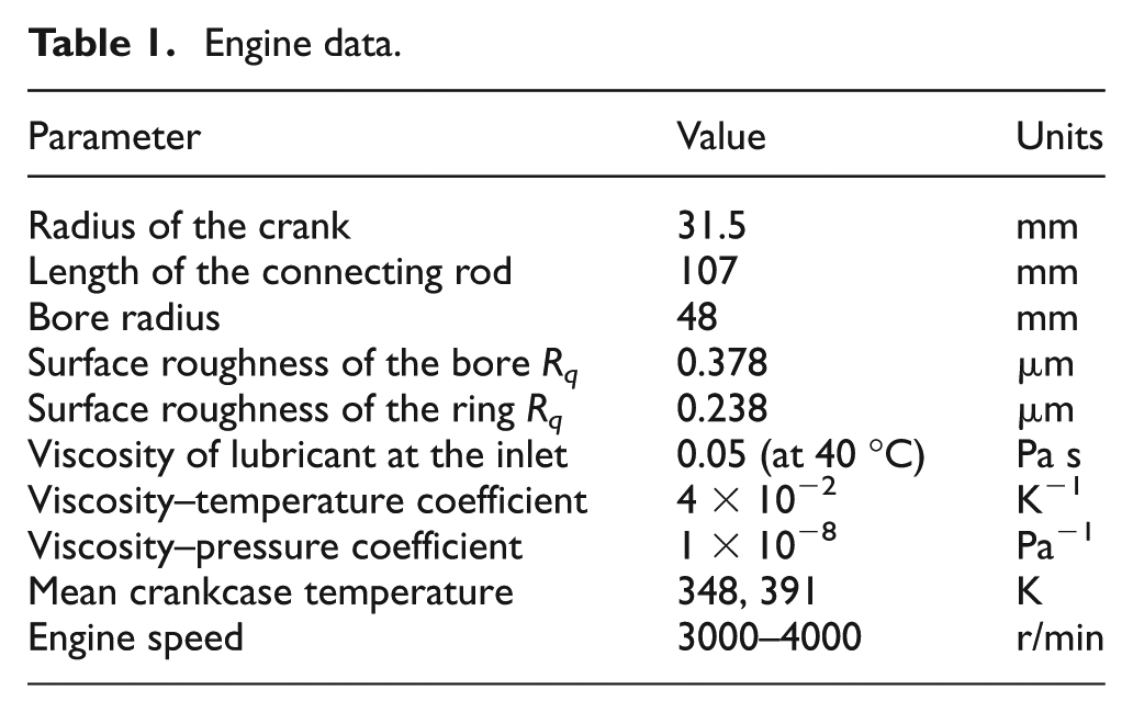
The analysis is conducted for typical running conditions of a single-cylinder Honda CRF 450R race engine, modified from its mono-block to a wet-liner arrangement. Table 1 provides the data used in the analysis. The results presented here are for an engine speed of 3000 r/min with 50% throttle, and an engine speed of 4000 r/min at full throttle, in both hot engine and cold engine conditions. The in-cylinder pressures at these speeds and engine loads for the modified Honda CRF 450R engine are shown in Figure 2.
Engine data.
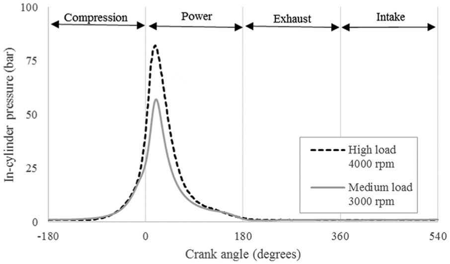
Variation in the measured in-cylinder pressure during the entire engine cycle.
The axial profile of the ring along its face-width plays an important role in the entrainment of lubricant into the contact conjunction through the inlet wedge effect (Figure 1). The wedge angle and the width of the ring significantly alter its load-carrying capacity and the lubricant film thickness, consequently also altering the extent of the counterface asperity interactions and boundary friction. A larger wedge angle (larger crown height) increases the lubricant availability in a fully flooded inlet and thus the film thickness, while increasing the flow rate 39 and oil loss, hence reducing the sealing functionality of the ring. Sealing is the primary function of the compression ring. Conversely, rings with smaller crown heights and consequently reduced inlet wedge angles result in lower rates of lubricant entrainment and thus thinner films, which can increase the boundary interactions.
It should be noted that, in most studies, the ring contact face profile is approximated as a parabola.13,16,17,37 The parabolic ring contact face-width profile is rather idealised but is retained in the current analysis.
Variables in the optimisation search space
Initial test runs with a variety of parameters are carried out to guide the range of values for the variables considered in the current study. These include the following.
The crown height of the ring contact profile. This is varied in the representative range 6–13 μm (Figure 1). The limitation of this range depends on the applicability of Reynolds equation for higher crown heights. Furthermore, measurement of real worn rings indicates that, after the running-in wear, the crown height falls within the stated range, irrespective of the new (unworn) form. A flat face ring profile is unrepresentative of the investigated engine. Furthermore, as a result of ring twist or bending, the profile as viewed from the contact deviates from a parabolic shape. A crown offset as discussed below is used to reduce this effect.
The crown height offset (Figure 1). In practice because of the different boundary conditions in the sense of sliding of the ring, the crown height is offset. In order to see this effect, the minima of the profile were shifted between −54 μm and 67 μm with respect to the crown height of the ring centre. A negative value means a shift of the minimum towards the crank case or the lower retaining ring groove.
The ring face-width. This has also been demonstrated to be an important parameter by Shahmohamadi et al. 17 It was shown that there is an optimum range for the ring width, as well as issues with regard to the ring mass and the modal response. This parameter is varied in the range 0.54–1.34 mm. For the engine under consideration, the currently manufactured ring width is in the range 0.8–1.2 mm.
The ring tension. This affects the loading conditions, particularly in the parts of the cycle where the chamber pressure is relatively low, such as in the intake and the exhaust strokes. A tension force per unit length of 8–26 N/m is used.
Objective functions
The main objectives are the energy efficiency, the light weight and durability.
Parasitic energy losses
These are the losses due to contact friction only. The energy loss throughout the engine cycle is calculated. The generated friction is a function of engine speed, consisting of the viscous shear losses of the lubricant film (proportional to the sliding speed in the main) and boundary friction losses, which are independent of the sliding speed (equation (10)) and mostly governed by the lubricant Eyring shear stress, the asperity geometry and the surface material. Figure 3 shows the variation in friction during an engine cycle. The values of all the variables in optimisation study are selected in the middle of their ranges to obtain the results shown in Figure 3.
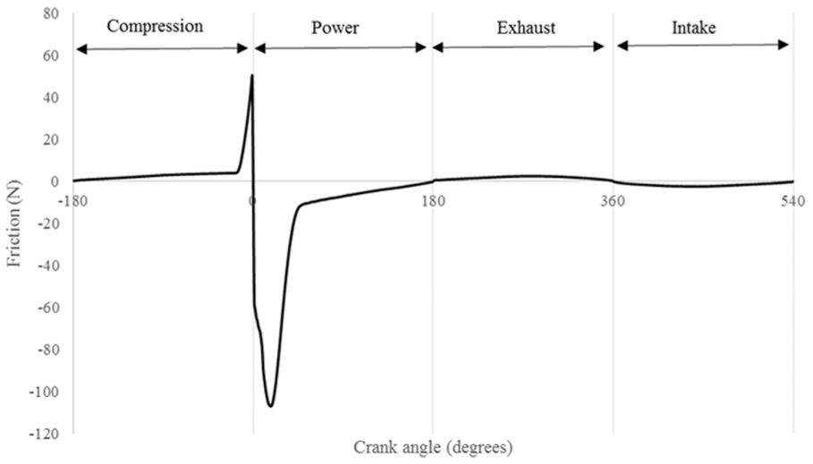
Variation in friction during an engine cycle at 3000 r/min with 50% throttle.
Figure 4 shows the effects of combinations of parameters including the shift of the crown height centre (i.e. the offset), the ring width, the ring tension and the crown height. The darkest region provides the minimum energy loss against the ranges of two of the selected parameters at a time. It is evident that there is an optimum range for these parameters. The effect of the ring width was studied by Shahmohamadi et al., 17 who showed that an increasing ring width enhances the load-carrying capacity as well as the shear stress. Thus, friction which is obtained from integration of the shear stress over the conjunction area and the consequent energy loss are reduced. This trend is also observed here up to a certain ring width after which the greater surface area on the back of the ring, which is exposed to the combustion pressure, increases the contact loading, decreasing the film thickness.
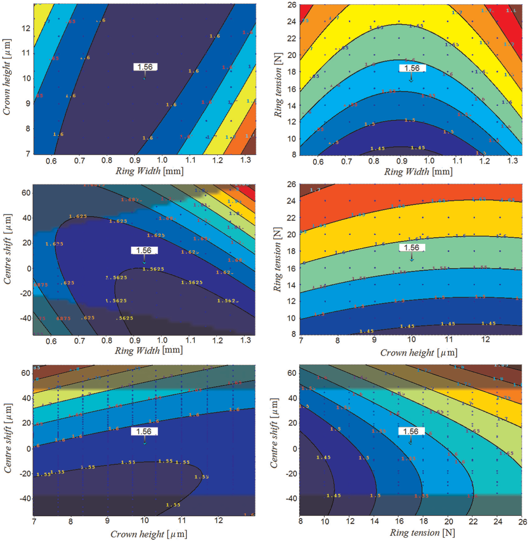
Variations in the total energy loss against different optimisation variables.
As expected, with increasing ring tension, the energy loss also increases owing to a decreasing film thickness. However, to find the optimum ring tension, it is also necessary to include the sealing effectiveness and the gas blowby in the analysis. 12 This is addressed elsewhere and is not included in the current work because of the expansive requirements for optimisation-driven simulation studies. For the effect of ring tension to be included in all aspects, ring dynamics and blowby, 12 as well as the cylinder out-of-roundness, should also be considered. 29 With regard to the centre shift (the offset), apart from quite thin rings, a larger offset in the negative direction generally reduces the energy loss. Exactly the same behaviour is observed for the crown height itself. Apart from very small (and generally undesired) ring widths (which also increase the propensity to twist in practice), increasing the crown height decreases the energy loss. This is due to the flooding of the contact, thus increasing the film thickness. It should be noted that fully flooded inlets are assumed in the current analysis.
In order to better understand the effect of the centre shift on friction, the variation in friction for a centre shift of ±60 μm is shown in Figure 5. All other parameters are kept in the centres of their ranges.
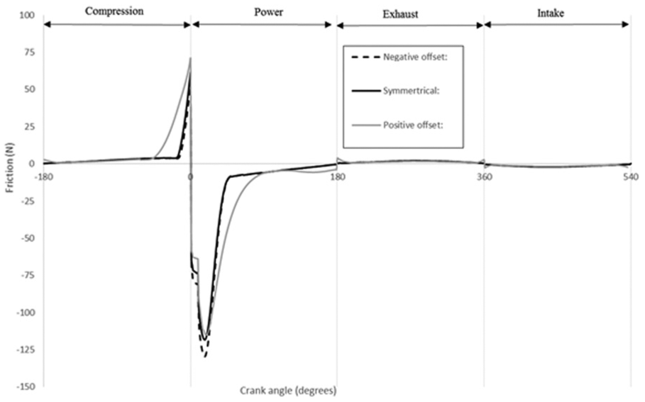
Variation in friction during an engine cycle for a centre shift of ±60 μm.
As is observed from this figure, a positive centre shift reveals high values of friction in compression strokes and the power strokes. These high friction values in conjunction with high sliding velocities far from the reversal points reveal a higher energy loss, which is also observed in Figure 4. The negative centre shift almost follows the symmetric profile apart from the power stroke, which is slightly higher than in the symmetric case. When the low sliding velocity in this range (close to the reversal point) is considered, the effect of this increase in friction is minimal, although it is not zero. This is also observed in Figure 4.
Percentages of the cycle time in mixed and boundary lubrication regimes
The percentage of the cycle time in mixed lubrication regime can be considered as an indicator of poor engine efficiency. It can also be an indicator of potential wear. Styles et al. 40 showed that in excess of 30% of all the frictional losses from the ring–liner conjunction occurs at the top dead centre reversal in transition from the compression stroke to the power stroke, where a mixed lubrication regime or a boundary lubrication regime dominates. This is also evident in the results in Figure 3. Therefore, minimisation of this is an appropriate objective function. Progressively, in practice, measures to mitigate this, such as surface texturing of the liner surface, are undertaken in order for such features to act as reservoirs of lubricant, inducing hydrodynamic lift, when the ring passes over them. This effect is considered as microhydrodynamics. 41 In the current study, the proportions of cycle time spent in mixed and boundary lubrication regimes are calculated using the percentages of the cycle from the Stribeck parameter: λ = h/σ < 4 (for in-cylinder applications 42 ). This is obtained by assuming a Gaussian distribution of the asperity heights, as in the Greenwood–Tripp 18 model. This model is widely used in the literature, including for in-cylinder applications. However, the usual cross-hatched and plateau-honed cylinder liner surface deviates from a Gaussian surface. The alternative is to measure the surfaces, to find a composite equivalent and to use numerical representation, which is outside the scope of the current paper. Leighton et al. 43 highlighted an approach for the description of non-Gaussian cylinder liner topography. Figure 6 shows the variation in the lubricant film thickness for the case of all parameters taken in their midranges for the entire engine four-stroke cycle. The grey dashed line corresponds to when the film thickness drops below the point at which boundary interactions are expected to occur (λ < 4).
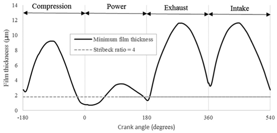
Minimum film thickness for an engine operating at 3000 r/min at a medium load with all the other parameters in their midranges.
Figure 7 shows the variation in this parameter against four different variables in two-by-two graphs, as previously. The percentage time for asperity interactions increases with decreasing lubricant film thickness. Therefore, in a similar manner to the other objectives (the reduced energy loss), an optimum ring width which yields minimum incidence of mixed and boundary lubrication regimes emerges. A higher ring tension yields a thinner film, as expected. Therefore, a higher percentage of the cycle resides in mixed lubrication regime. However, from a practical standpoint, it is noteworthy that a lack of ring tension can also lead to oil loss and blowby.
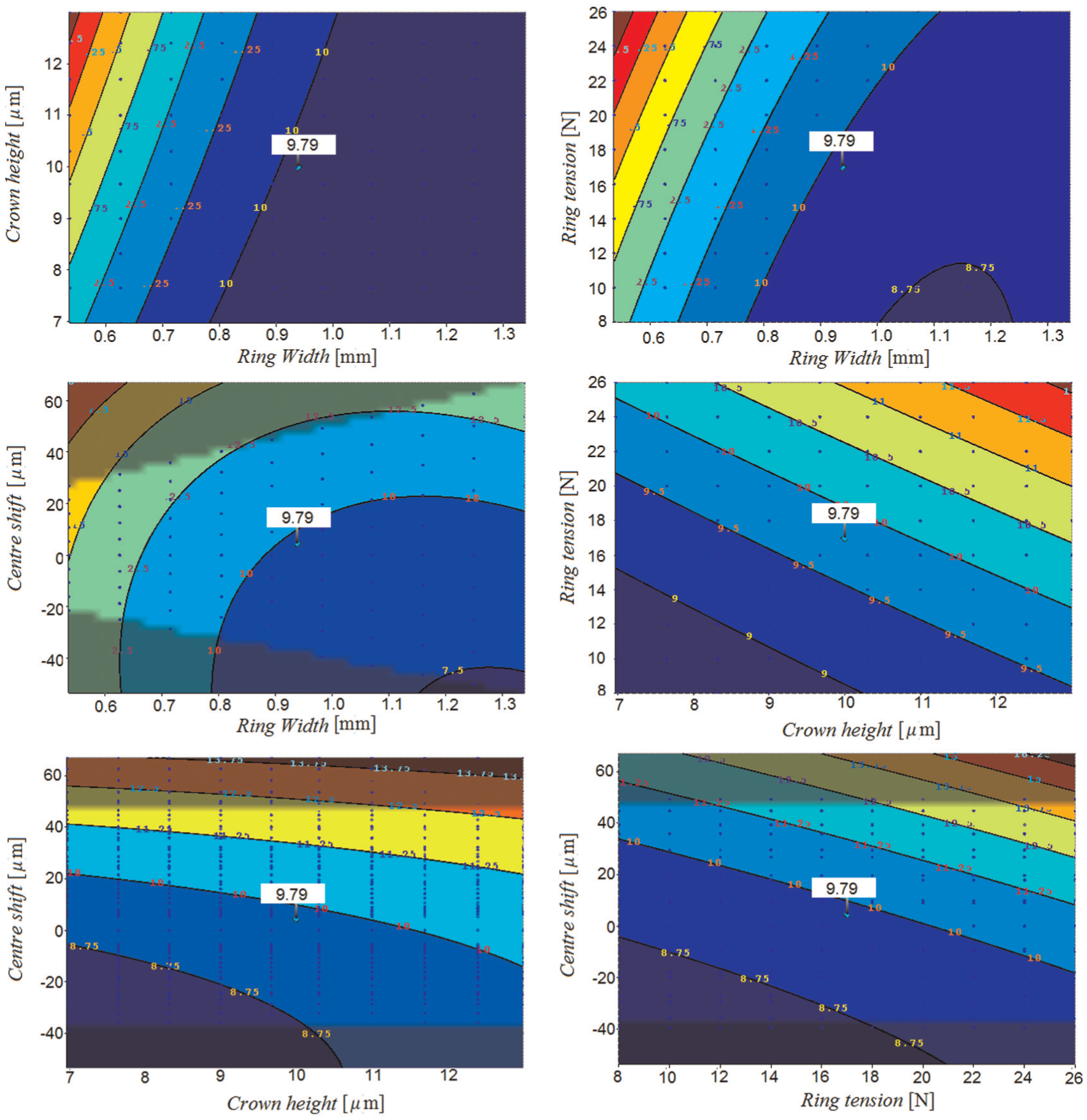
Variations in the percentage of cycle time spent in mixed or boundary lubrication regimes against different optimisation variables.
The change to the centre shift of the ring crown height also shows a similar trend for the incidence of the mixed lubrication regime and the energy loss. The shift of the centre of the ring towards the crank case (a negative value) increases the lubricant film thickness and consequently reduces the percentage of time spent in the mixed lubrication regime.
Figure 8 shows the variation in the film thickness over one engine cycle for a centre shift of ±60 μm. All the other parameters are again kept in the midst of their ranges. The figure shows that, with a positive centre shift, the mixed lubrication regime occurs for a much higher percentage of the cycle (43.3%). With a negative centre shift, the percentage of occurrence of the mixed lubrication regime is almost insensitive and decreases slightly to 9% in comparison with 9.3% for the symmetric profile. These results can also be observed in Figure 4.
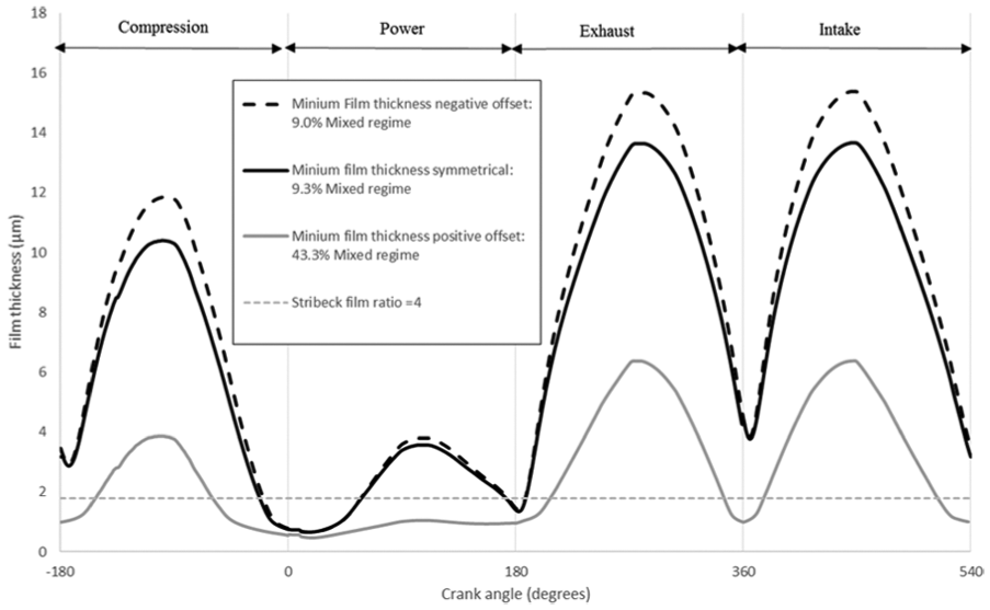
Variation in the film thickness over one engine cycle for a centre shift of ±60 μm.
Ring mass
An important objective is to reduce the mass and the inertia of all the powertrain components. In the case of the compression ring, its mass affects its inertial dynamics, e.g. the occurrence of ring flutter or ring jump. These are significant as leakage also leads to inefficiency of the engine. In addition, there are also practical engineering considerations which may inhibit the use of certain ring geometries. At high speeds, the ring is subject to high inertial forces, which potentially reach the critical limit for ring jump (i.e. unseating of heavier compression rings from their lower sealing face). Indeed, in ISO 6622-2:2013 44 it was suggested that the ring widths should be limited to an upper limit of 2.5 mm, which is considered in the current study. Therefore, the general objective is focused on minimising the ring mass. In practice, a thin ring can be subject to a considerable modal response (radial in-plane vibrations and axial out-of-plane twist27,28), which can results in a loss of sealing, increasing blowby and reverse blowby.
A second-order polynomial function of the objectives is constructed. The predicted conformance of the outcomes to the polynomial fit is shown in Figure 9. The closeness of fit determines the accuracy of the optimisation process. The limiting number of iterative generations used for the genetic algorithm procedure is set at 200, with the population size of 200 in each successive generation. 24 Since this is a guided stochastic optimisation process, the procedure is repeated 20 times in order to ensure good repeatability of the outcomes.
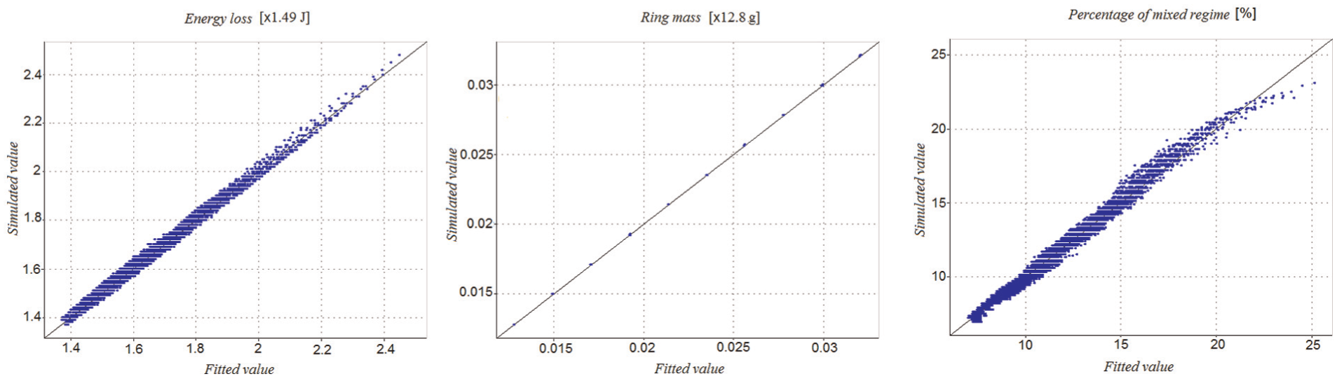
Graphs of the simulation outcomes: goodness of fit.
After running the entire process for both hot engine conditions and cold engine conditions, the trade-off graph for both conditions is presented in Figure 10.
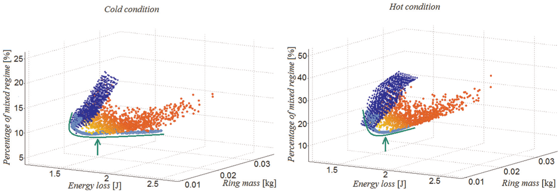
Trade-off variations.
It should be noted that the multi-objective nature of the study results in a series of optimum conditions which may be chosen on the basis of any stated design priorities. Each point on the plot of Figure 10 is obtained with a unique combination of parameters. Light grey full circles show that the combination of parameters leads to objectives which are far from the best desired range (which are the minimum values of objectives in this paper). Dark grey full circles show combinations which are closer to this demanded range. The grey solid curves indicate the preferred region for reduced energy loss and lowest incidences of the mixed lubrication regime and boundary lubrication regime during the cycle. This is over the entire range of possible ring masses. Up to the middle of the ring mass range (primarily a function of the ring width and, to a much lesser extent, the ring face profile), a reduction in the energy loss and a reduction in the percentage incidence of the mixed lubrication regime is observed. Thereafter, increasing the ring mass results in no significant gain in the stated objective functions. As it proves to be the case, an increased ring mass introduces other untoward repercussions, as stated above. The same optimum range (shown by the grey dashed curves) is predicted for both hot engine running conditions and cold engine running conditions. Therefore, a desired design can be chosen from the indicated range of the ring masses for both hot engine running conditions and cold engine running conditions.
Figure 11(a) and Figure 11(b) show the predicted film thickness and the generated friction respectively for the entire four-stroke engine cycle with an optimum design arrived at for both hot engine running conditions and cold engine running conditions. The engine is running at 4000 r/min at a high load; the in-cylinder pressure distribution is displayed in Figure 2. At higher temperatures, because of the thermal thinning of the lubricant, a reduction in the film thickness is evident. As a result, the contact condition remains in the mixed lubrication regime for most of the power stroke, incurring higher frictional losses.
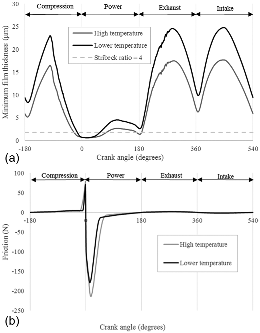
Variations in (a) the minimum film thickness and (b) the generated friction during an engine cycle for the optimum design parameters.
Table 2 lists the calculated values of the objectives for both hot engine running conditions and cold engine running conditions.
Optimised design objectives for hot engine running conditions and cold engine running conditions.
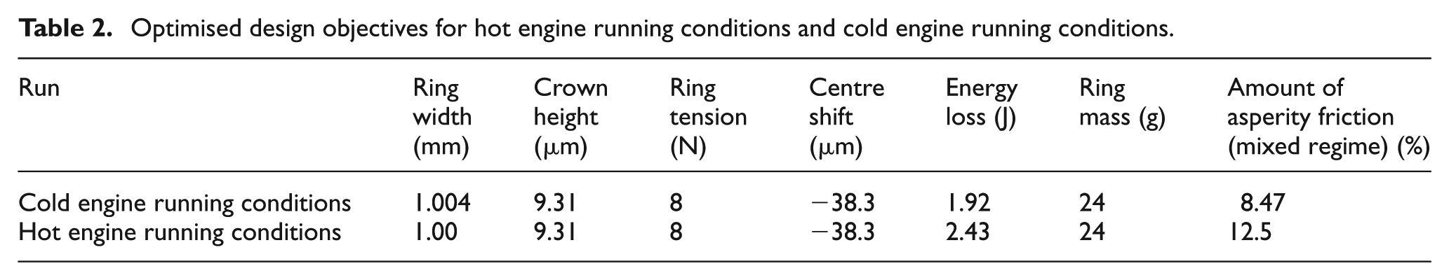
Remarkably, the results obtained reflect the current ring width and mass of the current model of Honda CRF 450R engine (0.891–1.1 mm). It is not clear how the original equipment manufacturer had arrived at the same outcome.
Concluding remarks
The paper presents a mixed thermodynamic–hydrodynamic analysis of piston compression ring–cylinder liner contact. A combined solution of Reynolds equation and asperity interactions is integrated with an optimisation procedure based on a genetic algorithm. The compression ring–bore contact undergoes a broad range of cyclic lubrication regimes, with a significant part of the engine cycle subject to asperity interactions. For all engines, particularly those for motorsport applications, the fuel efficiency is a key design objective as well as lightweight and compact components. These parameters, among a host of other influential interacting parameters, may be considered in an optimisation process to improve upon the stated objective functions. A multitude of simulation runs highlight potential regions for the optimal objective functions based on the selected parameters. As in any engineering exercise, some degree of trade-off is essential to arrive at a practical optimum set of parameters which must also comply with international set standards as well as ease of manufacturing, assembly and costs, the last of which is of lesser concern within the context of motorsport. Remarkably, within these constraints the optimisation-driven simulations for both hot running engine conditions and cold running engine conditions point to a unique practical solution.
The current study makes a number of assumptions, such as a plentiful supply of inlet lubricant to the conjunction and full peripheral conformance of the ring to a right circular cylindrical liner. Under these conditions, the issues of oil loss, its degradation and blowby as well as starvation are not taken into account. These issues remain the motivation for further improvement of the proposed model.
Footnotes
Appendix 1
Acknowledgements
Declaration of conflicting interests
The author(s) declared no potential conflicts of interest with respect to the research, authorship, and/or publication of this article.
Funding
The author(s) disclosed receipt of the following financial support for the research, authorship and/or publication of this article: This work was supported by the Engineering and Sciences Research Council under an Encyclopaedic Program Grant (Grant Number: EP/G012334/1).