
Abstract
Piston–cylinder interactions account for a significant portion of frictional losses in an internal-combustion engine. This is mainly as the result of significant changes in the operating conditions (the load, the speed and the temperature) as well as the contact geometry and the encountered topography during a typical engine cycle. These changes alter the regime of lubrication which underlies the mechanisms of friction generation. The multi-variate interactive nature of the problem requires quite complex analyses which do not fully replicate the actual in-situ conditions. Therefore, there is a need for direct measurement of cyclic friction under controlled conditions. The paper describes the use of a novel floating-liner arrangement which is capable of direct measurement of friction, its transitory mechanisms, as well as determination of the regime of lubrication.
Introduction
Road transport is now inexorably linked to modern living. It is also one of the underpinnings of economic development and its sustenance. However, nearly all vehicles rely on fossil fuels as the means of propulsion. The scarcity of these resources and the adverse effects of the ensuing emission products are gradually pressuring engine designers and developers to adhere to improving the fuel efficiency and to reducing the emissions. Alternative sources of propulsion power as well as energy recovery are also being actively pursued. Irrespective of the means of propulsion chosen, parasitic losses, mostly friction, will be regarded as a nemesis and an important energy sink.
Friction accounts for 15–20% of all the internal-combustion engine losses. 1 The share of frictional losses increases at idling and low speeds such as those in crawling congested traffic. This is the case in the urban areas and even increasingly on major trunk routes. Therefore, a reduction in friction is seen as essential in the development of new engines, which is driven by a number of key concerns: the fuel efficiency, the emission levels, the noise, vibration and harshness refinement and the cost. It is also noteworthy that the transport sector accounts for 14% of the worldwide greenhouse gas emissions. 2
The piston system accounts for 40–50% of all the parasitic losses; these include friction as well as the heat generated in load-bearing conjunctions, which is conducted away through the bounding solid surfaces. 3 Furthermore, this is the key subsystem where the interrelationship between thermodynamics, inertial dynamics, elastodynamics, tribology and emissions becomes the most pronounced; this is a relationship which often poses paradoxical design issues. For instance, very tight sealing functionality of the compression ring can often be a concern because of its potential adverse effect on friction.
There have been considerable predictive analyses from the multitude of piston–bore conjunctions, including the top compression ring,4–6 the oil control ring and the piston skirt.3,7–9 The analyses have often been confined to one of these conjunctions without regard to their interconnected behaviour. Additionally, the complexity and multiplicity of interactions have often necessitated the exclusion of certain phenomena. For example, the combination of the elastodynamics of the compression ring and the transient hydrodynamics has been rarely reported. Baker et al. 10 showed that, while the ring modal behaviour caters for its sealing function, its longer settling time guards against complete conformance to an idealised right circular cylinder, which would otherwise result in excessive friction. With thin films of the order of a few micrometres at best, particularly at piston reversals, boundary interactions account for a significant portion of cyclic frictional losses. Many studies have included the effect of surface topography, excluding ring modal behaviour, in predicting friction.4–6,11,12 Others have also included the effect of surface treatments, such as coatings 13 or cross-hatch honing of cylinder liners 14 or inclusion of a laser-textured liner surface at piston reversal at the top dead centre (TDC) in piston skirt lubrication. 15
Bore out-of-roundness is another key parameter, which affects the conjunctional geometry, and thus friction and the ring-sealing function, as well as the oil loss, potential blow-by and lubricant degradation.16,17 Furthermore, the process of wear changes the geometry of the contiguous solids as well as the surface topography, which affect the tribological conditions in the ring–bore contact.13,17–19
Generated heat due to combustion and to a lesser extent that generated in the contact conjunction itself alters the viscosity of the lubricant, as well as causing thermoelastic distortion of the piston skirt. These significantly affect the tribological conditions and require thermoelastohydrodynamic analysis. Morris et al. 6 demonstrated a considerably reduced film thickness in the compression ring–bore contact with generated heat, and Littlefair et al., 20 McClure 21 and Bai 22 took into account the thermoelastic distortion of the piston skirt in their piston skirt lubrication studies.
It is, therefore, clear that any realistic analysis would necessitate inclusion of a plethora of interactive physical phenomena in order to replicate realistic engine running conditions closely. Although good agreement has been reported between predictions and controlled laboratory-based motorised engine tests, such as the predictions by Akalin and Newaz 23 and Mishra et al. 5 with the experimental work of Furuhama and Sasaki, 24 still direct measurement of friction under in-situ fired engine conditions is essential. The work by Furuhama and Sasaki 24 was a culmination of the original work by Furuham and Takiguchi, 25 measuring the forces transmitted to a floating liner whose motion was restricted through a set of intervening piezoelectric transducers. The infinitesimal (of the order of a few micrometres) motion of the liner generates inertial force responses proportional to the resistive force, which is friction, having taken into account the variations in the gas pressure loading. This principle was used by other researchers such as Yoshida et al. 26 in the measurement of friction for different surface treatments.
This paper presents an instrumented floating liner, incorporated within the cylinder block of a high-performance single-cylinder motocross motorcycle engine, the piston ring pack of which consists of a compression ring and an oil control ring. The engine employs a short compliant partial piston skirt on the thrust–anti-thrust plane. The piston traverse speed range is 0–35 m/s (with a maximum engine speed of 10,000 r/min) with maximum side loads of the order of 5 kN. This combination more than envelops the expected performance of any original equipment manufacturer (OEM) engine and matches almost all those used by the racing fraternity.
Principles of operation of a floating liner
The principle of a floating-liner device is to suspend the liner in such a way that a number of piezoelectric load cells intervene at any point of contact between the liner and any rigidly mounted components. 27 Figure 1 illustrates the assembly which contains the floating liner, held within a fixture through three piezoelectric load cells positioned at 120° spacing. As the piston assembly reciprocates, the applied forces on to the liner cause infinitesimal movements of the liner relative to its rigidly held fixture within the engine cylinder. These forces are measured by the intervening load cells as
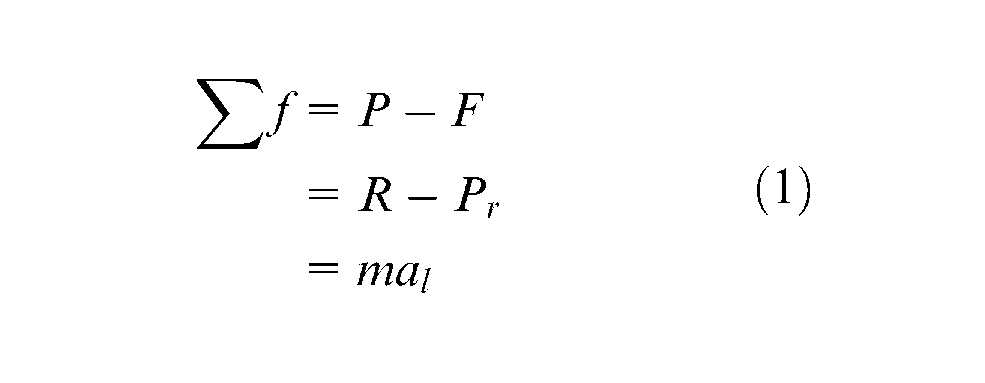
The load cells are preloaded at
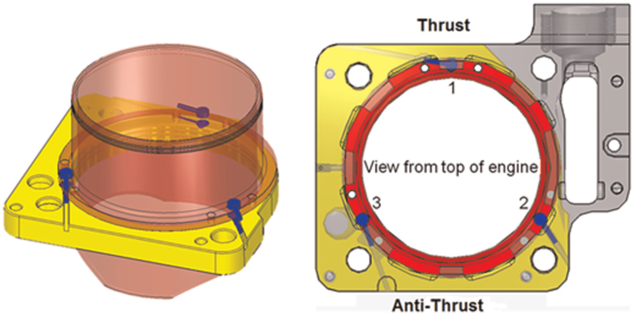
The floating liner.
Hence, friction is directly measured as noted by O’Rourke et al. 29 Therefore, care should be taken to ensure that the in-cylinder gas pressure acts directly on to the liner’s top peripheral rim and not to the holding fixture. If the pressure is applied to the holding fixture, then additional forces would act through the fixture to the load cells and result in erroneous readings. To prevent these spurious in-service readings from the cylinder head clamp loading and unloading due to gas pressure, a labyrinth seal is employed. This allows decoupling of the required seal clamping load from the actual liner, thereby allowing quasi-unconstrained infinitesimal vertical displacements.
Figure 2 shows the top constrained 20MnV6 alloy steel seal ring (vertically constrained), which is an overhanging precision fit over the floating liner of the same material. The internal diameter intrusion of the alloy steel seal ring requires a stepped piston crown as shown in the figure.
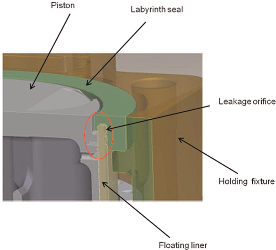
The sealing arrangement at the top of the floating liner.
Unlike other floating-liner arrangements, where a spring–damper arrangement is used to palliate any shock loading of the liner, the use of a labyrinth seal ensures smooth-running frictionless operation at the liner top rim, but at the expense of some side leakage of gas through the sealing orifice (gap) as shown in the figure. Therefore, a miniature Kistler pressure transducer is inserted through the gap in order to measure the leakage pressure and to apply the correct applied pressure to obtain the liner pressure load as
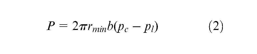
Friction can now be obtained directly from equation (1) as
The engine test-bed
A Honda CRF450R motocross motorcycle engine was chosen because of its relatively high engine speed (10,000 r/min), high power (41 kW) and high torque (50 N m) (bore diameter, 96 mm; stroke, 62.1 mm). This choice is representative of the highest-performing, naturally aspirated single-cylinder engine technology (i.e. over 90 kW/l and 110 N m/l). Its high-speed and high-load characteristics envelops the transient tribological conditions encountered in a very wide range of engines. The engine OEM barrel was replaced by a wet barrel containing the floating liner. For the short-duration testing, typically less than 5 min, natural air cooling was found to suffice. Rubbing thermocouples on the outer surface of the liner and control of the bulk oil temperature ensured testing repeatability. The diameter of the available load cells, the minimum recommended wall thickness of the liner (advised through use of finite element modal analysis 27 ) and the engine architectural constraints exclude the use of a low-elastic-modulus light-alloy cylinder liner. Furthermore, load cell structural bending limitations and stress concentrations due to the concentrated loads preclude the use of an aluminium alloy. Therefore, low-alloy steel 20MnV6 is chosen in the construction of the floating liner. This is because of its long successful use in cylinder liner applications when coated with Ni–SiC bore coating (Capricorn Automotive Ltd) which is common on both aluminium and steel liners. The piston–steel liner nominal clearance is 100 μm.
Because of the differential operating temperature, there is a need to control the clearance between the cylinder liner and the housing, and thus to minimise the induced stresses in the OEM aluminium structure. The choice of housing material was restricted to materials with a coefficient of thermal expansion between 16 ppm/K and 18 ppm/K, and a yield strength significantly higher than that of the original donor engine barrel. Austenitic stainless steel grade 304 satisfies these criteria, with the added benefit of minimal corrosion in an aqueous environment.
The engine was mounted on to an Oswald 250 kW transient dynamometer. The assembly incorporates the engine with transmission engaged in second gear with a speed ratio of 4:1. All the standard engine testing parameters (the chamber pressure, the air-to-fuel ratio, the test cell humidity, the test cell temperature, the input temperatures of the fuel and the coolant, etc.) were logged as well as friction to ensure the reliability and consistency of the acquired results. Table 1 provides the controlled running conditions for motorised engine conditions as well as fired engine conditions. The basic set-up is shown in Figure 3.
Test conditions.
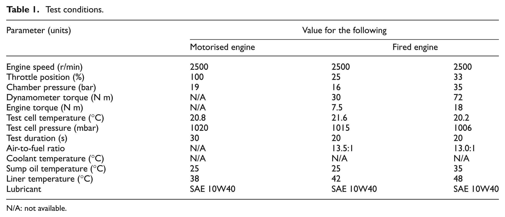
N/A: not available.
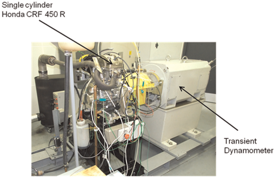
The engine test-bed.
Testing for floating liner operational integrity
The first step in the testing procedure is to ascertain the operational integrity of the floating-liner system. Referring to equation (1), it is clear that, with the cylinder head removed (Figure 4(c)), there is no significant pressure loading of the liner. Thus, the only applied force to the liner would be friction as the result of its interactions with the piston:
where
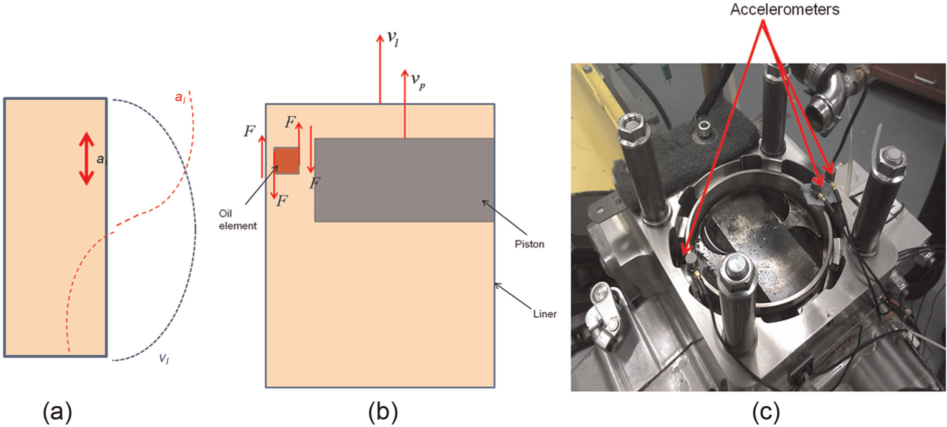
Floating liner with the cylinder head off: (a) liner kinematics; (b) friction generation; (c) measurement of the inertial dynamics.
The viscous friction is
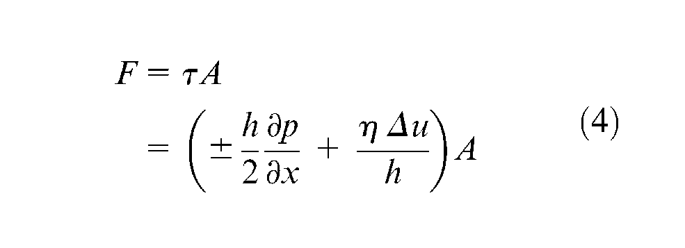
where the Poiseuille shear (the first term in the parentheses) is insignificant because of the small pressure gradient in the axial direction of the piston with an open cylinder head. Hence, the friction
Measured friction with cylinder head removed.
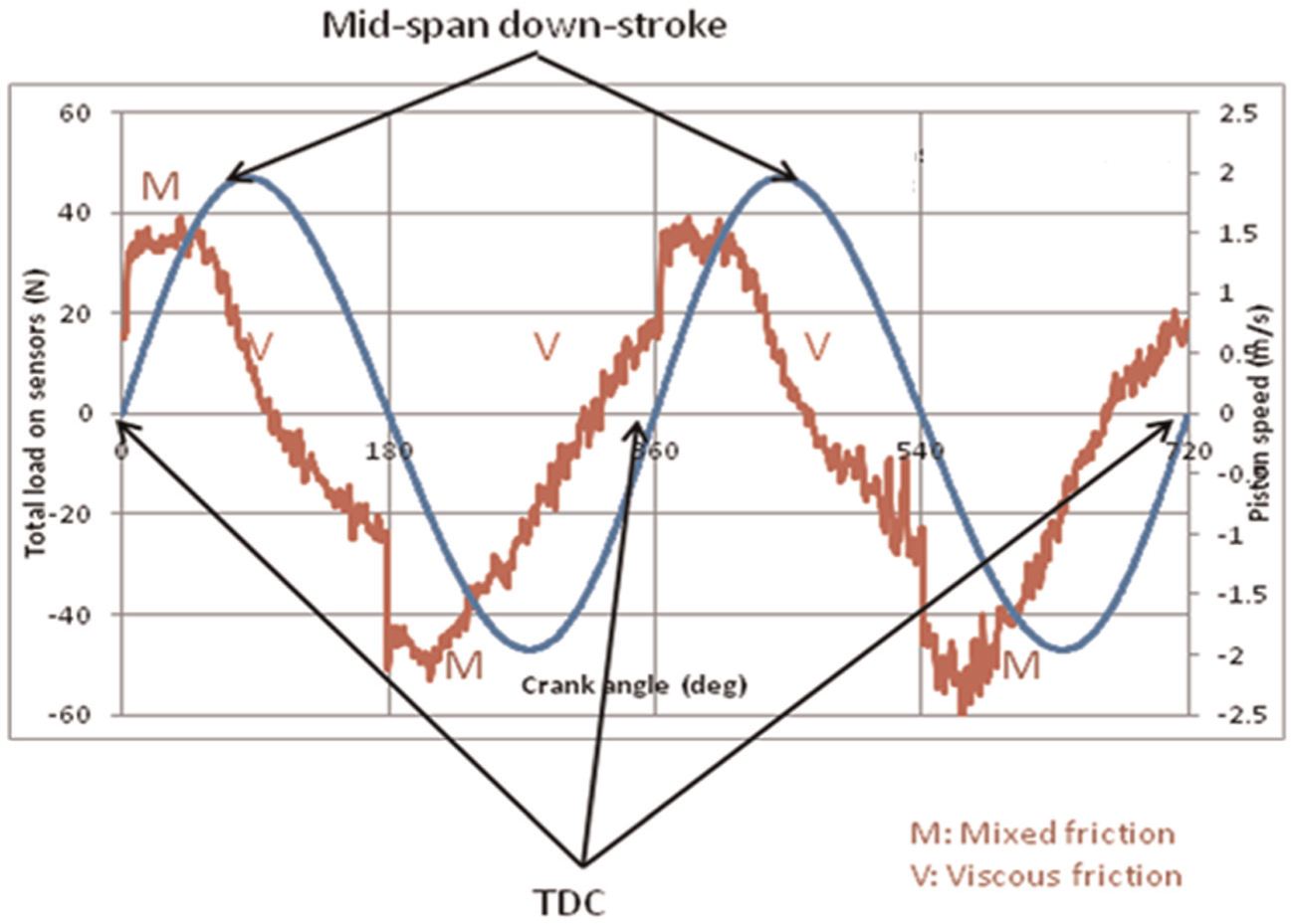
Figure 5 shows the measured friction at the engine speed of 500 r/min;
Engine friction under motorised and fired conditions
Most reported work with floating liners incorporated in test rigs or engines has been related to motorised engine running conditions or has been undertaken in quite-low-speed fired tests with significant noise and vibration.23,25,26,29 However, some improvements have been made to enable measurements under fired conditions, e.g. in the paper by Furuhama and Sasaki. 24 The motorised tests represent relatively cold running conditions; at low engine speeds, this corresponds to some urban driving conditions which can lead to more significant viscous frictional power loss and increased emissions. These conditions constitute parts of the North American emission cycle tests and the New European Emission Driving Cycle. 31 These conditions also reduce the large number of interactions that occur under fired engine running conditions, which are initiated by reduced lubricant viscosity (thinner films, and thus increased boundary interactions) and thermoelastic deformation of the liner and the piston skirt, thus reduced the running clearances.20–22
Morris et al. 6 have shown through numerical analysis that thermal mixing at the inlet of the compression ring–liner contact results in a rise in the lubricant temperature above that of both the contiguous solid boundaries as the result of convective heat transfer from the surfaces into the entrant lubricant, and its subsequent shear heating. Therefore, under motorised conditions, with low solid boundary temperatures, the lubricant contact temperature remains only marginally above that in the bulk (the sump temperature). Consequently, the relatively high viscosity of cold lubricant in the motorised tests means that the dominant cyclic friction is due to lubricant viscous action in the presence of any film of lubricant. The other source of lubricant shear is due to the Poiseuille flow at the conjunctional inlet at the TDC reversal, if significant chamber pressure is generated under the motorised condition, which is around 19 bar for the Honda CRF450R engine with the cylinder head in place and motoring at 2500 r/min (Figure 6). Therefore, unlike other reported test rigs, the effect of realistic pressure loading, particularly on the compression ring conjunction, is included in the current motorised tests.
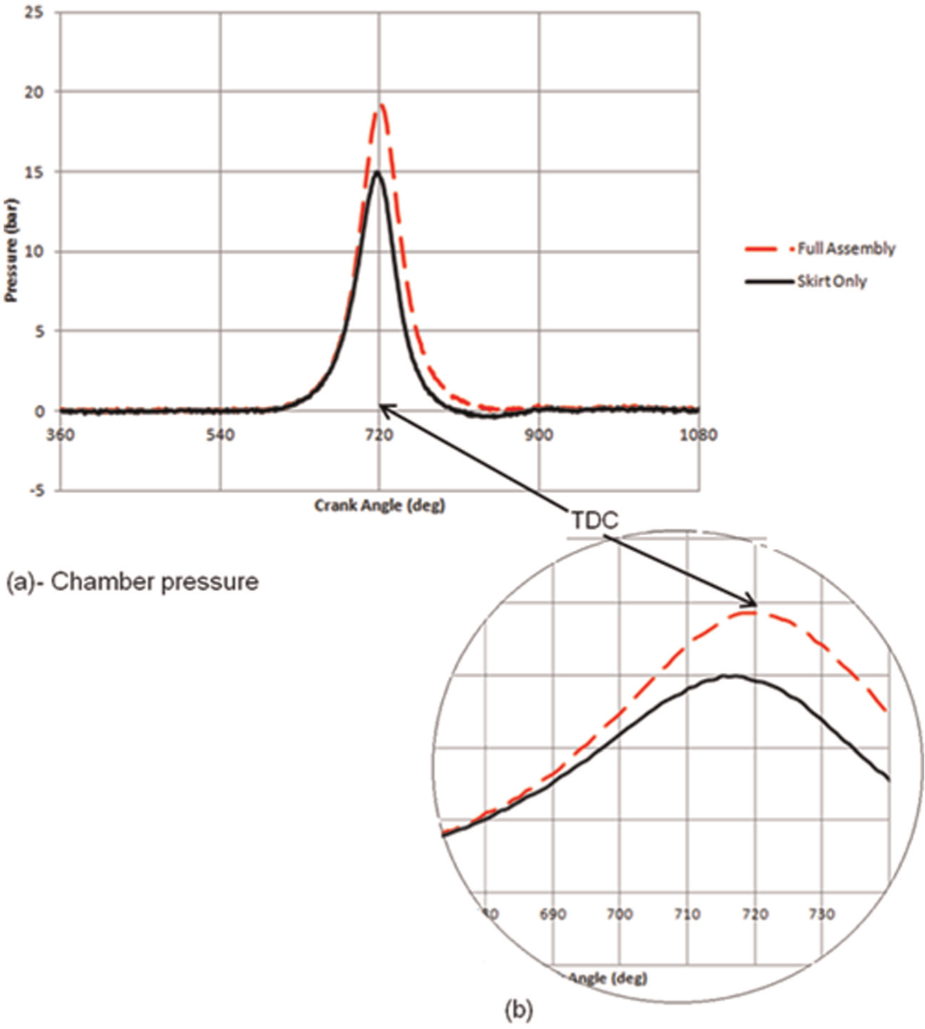
Chamber pressure under the motorised condition at 2500 r/min.
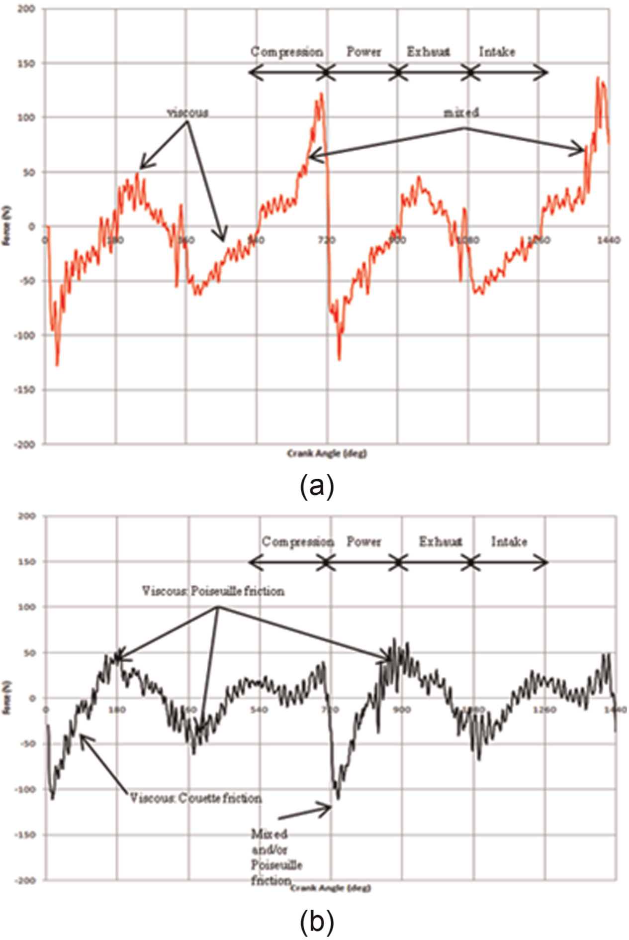
Figure 7(a) shows the measured friction by the floating liner at 2500 r/min. The TDC position is at 720° crank angle (in transition from the compression stroke to the power stroke). The maximum chamber pressure of 19 bar occurs at this position and every 720° crank angle thereafter. Positions at 180° crank angle and every 360° thereafter correspond to the reversal at the BDC. Friction changes the sense of application at the motion reversal positions. There are slight differences in the friction characteristics at the BDC from the power stroke to the exhaust stroke and from the intake stroke to the compression stroke. The higher friction in the former transition (i.e. the power stroke to the exhaust stroke) is because of a higher pressure gradient change. As in the case of an open cylinder (i.e. head off), the regions in which the friction trace remains proportional to the service parameter
Measured friction under motorised conditions: (a) complete piston assembly; (b) piston skirt conjunction only.
With the piston fairly closely conforming to the floating liner, it is possible to remove the two piston rings in this configuration (a compression ring and an oil control ring). Figure 7(b) shows the measured friction characteristics with the piston skirt only. Comparison of the result with that of the complete piston assembly (including the rings) shows some interesting features. First, the stipulated friction due to the Poiseuille shear occurs precisely at the BDC reversal from the power to the exhaust stroke (at 180°, 90°, etc.) rather than the somewhat delayed peak in Figure 7(a). This is because the compression ring remains at the bottom piston groove land at the BDC reversal which maintains a pressure gradient; this is not present when the ring is removed. The noted difference provides an indication of compression ring action. Namazian and Heywood 32 showed experimentally that the compression ring remains at the bottom of its groove from the BDC to the midstroke position.
At piston midspan positions, the viscous friction is significantly decreased, because without the oil control ring the skirt–liner conjunction is flooded. Friction in transition from the compression stroke to the power stroke (0° and 720°) is reduced at the reversal, because of a flooded inlet due to the lack of an oil control ring . Hence, the rise in friction prior to the TDC is entirely due to reduced Poiseuille flow shear loading. With a compression ring present, the peak transition friction occurs closer to the reversal, again as the ring moves this time from the bottom groove land. This is clearly observed in the difference between the measured chamber pressure variation near the TDC for the full piston assembly and that for the skirt only (Figure 6(b)). The sharp rise in friction in the power stroke is due to a combination of Poiseuille shear and somewhat reduced boundary interactions.
An overall comparison of Figure 7(a) and (b) shows that piston–liner friction is mainly governed by the compression ring sealing at the reversals, particularly in the transition from the compression stroke to the power stroke. At the BDC reversals and at the TDC in transition from the exhaust stroke to the intake stroke, the Poiseuille shear is the dominant source of friction, which can be affected by the axial flutter of the compression ring. The delayed nature of Poiseuille friction due to axial motionof the ring is indicative of the crucial sealing role of the compression ring. Another important observation from the motorised test results is that, for most of the engine cycle, lubricant shear (as the result of either Couette flow or Poiseuille flow) accounts for the main contributions, except for the TDC reversal from the compression stroke to the power stroke. However, this may not directly correspond to the fired conditions of a real engine.
The fired engine results, corresponding to steady running conditions at an engine speed of 2500 r/min, a torque of 30 N m at 25% throttle and a maximum combustion pressure of 16 bar at 13° past the TDC in the power stroke, are shown in Figure 8.
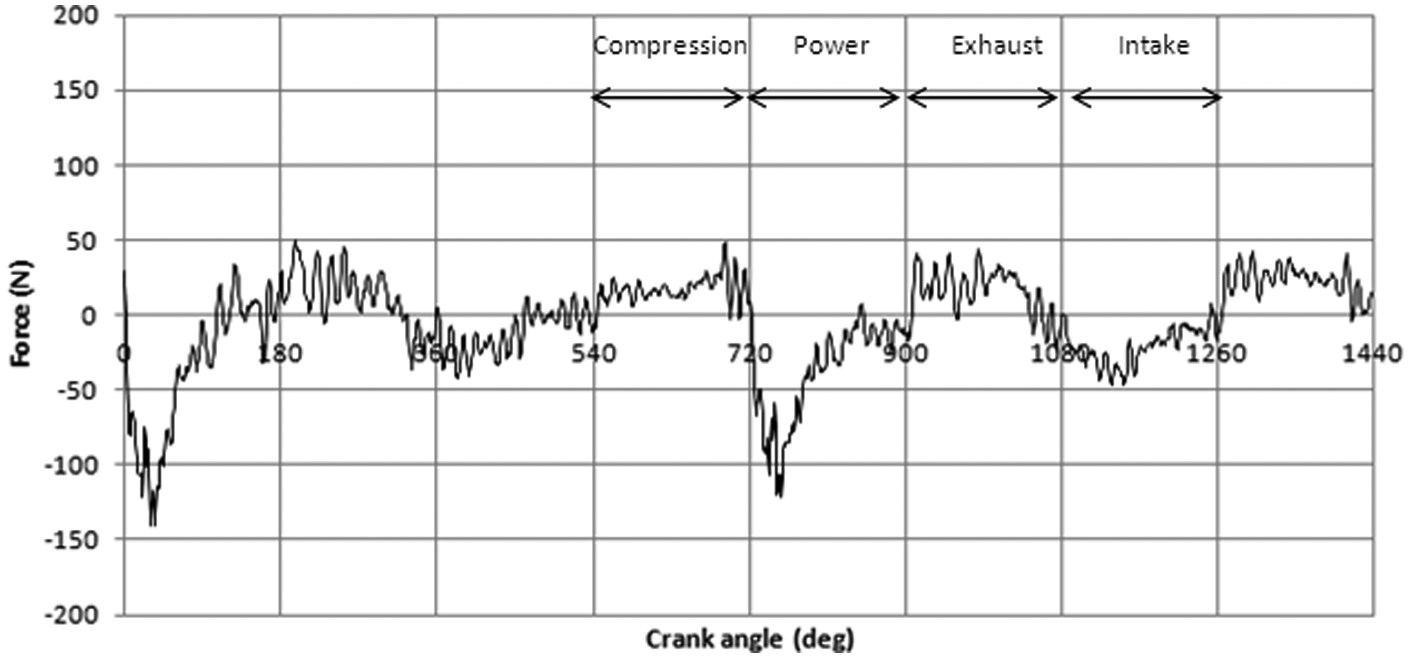
Measured friction under fired engine conditions at an engine speed of 2500 r/min and a torque of 30 N m.
A comparison of the results in Figure 8 with those in Figure 7(a) shows a number of important changes. First, as would be expected, the contribution to friction due to the viscous shear of the lubricant film is decreased because of the lower effective viscosity (equation (4)) caused by the rising temperatures of contacting bounding solids under fired conditions. Note that the bulk oil temperature at 25 °C is increased above the liner temperature at the contact inlet and is further increased through shear in transit through the contact. 6 Thus, the entrant lubricant flows into the contact of all the piston–liner conjunctions at a higher temperature. As the result of short testing times the difference between the liner temperature for motorised conditions and that for fired conditions is only a few degrees Celsius in these cases. However, with longer testing periods a larger difference would be expected. There is a significant reduction in friction at the TDC reversal in the latter stages of compression under fired conditions. This is because of a higher side load (engine torque), and the compression ring sealing function is enhanced. Thus, there is a lower pressure gradient dp/dx across the ring as well as a reduced film thickness due to a lower lubricant viscosity, as already noted. Therefore, the influence of Poiseuille shear (h/2)(dp/dx) is significantly decreased in comparison with the motorised results in Figure 7(a). Immediately upon reversal and within the power stroke, however, friction is increased under fired conditions because a thinner lubricant film results in increased boundary interactions.
Conclusions
The use of an instrumented floating liner has indicated the transient nature of the regime of lubrication in piston–cylinder conjunctions. It is shown that hydrodynamic, mixed and boundary regimes of lubrication are encountered in an engine cycle, the latter two at TDC reversals in transition from the compression stroke to the power stroke. During most of the engine cycle, friction is dominated by the viscous action of the lubricant film as a function of the sliding velocity of the piston, except for the reversals at the TDC (excluding that from the compression stroke to the power stroke) and BDC, where the change in the contact pressure gradient causes significant Poiseuille shear. The design provisions made with the floating liner enables the piston rings to be removed under motorised conditions. The measured data showed that the influence of the compression ring sealing upon friction is pertinent at piston reversal positions and particularly at TDC reversal prior to the power stroke. The ensuing mixed regime of lubrication at this juncture represents a significant portion of cyclic friction. As the engine torque is increased towards 33% wide-open throttle the dominance of this source of cyclic friction becomes more apparent (Figure 9). Therefore, to reduce piston–cylinder friction, it has been surmised and numerically shown3,15 that surface texturing at the TDC reversal would be beneficial. The results of the current investigation support this supposition. A thicker lubricant film would reduce compression ring–cylinder interactions at the TDC from the compression stroke to the power stroke but can also lead to lack of sealing and oil loss. Investigation of this aspect of work, using localised textured liner surfaces with the floating liner constitutes the future direction of the current research. Another important point is the inherent unbalanced nature of single-cylinder geometry, rendering an unbalanced response at a multitude of engine order harmonics. 30 This results in a certain amount of noise content in the floating-liner dynamics, and thus in the load cell signals, which is more significant at lower engine loadings (e.g. Figure 8 when compared with Figure 9). Therefore, some multi-cylinder testing may be beneficial for future work.
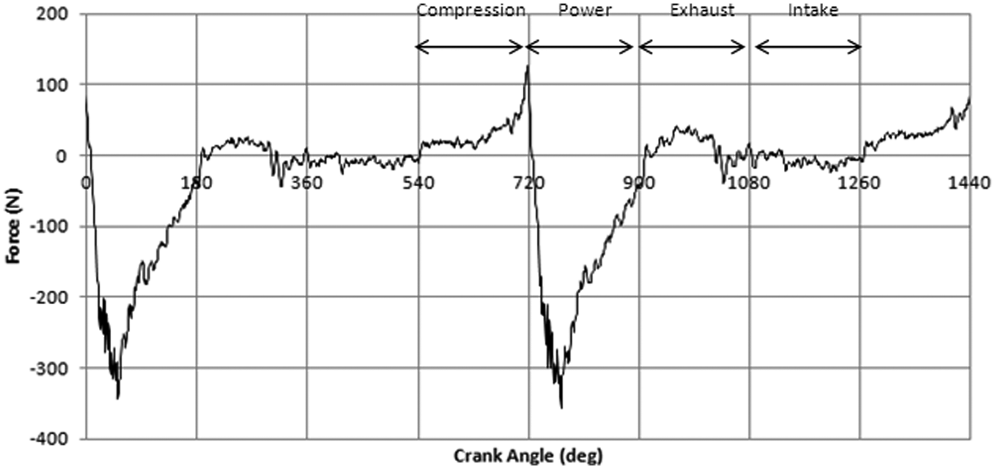
Measured friction under fired conditions at an engine speed of 2500 r/min and a torque of 72 N m.
Footnotes
Appendix 1
Acknowledgements
The authors acknowledge the technical support of a consortium of industrial concerns whose participation in this work is also acknowledged, particularly in this instance Capricorn Automotive Ltd.
Declaration of conflict of interest
The authors declare that there is no conflict of interest.
Funding
This work was financially supported by the Engineering and Physical Sciences Research Council with the Program Grant: Encyclopaedic (grant number: EP/G012334/1), under which the current research is conducted, and a consortium of industrial concerns, including BP Castrol, Aston Martin Lagonda, Capricorn Automotive, Ricardo Consulting Engineers, ProDrive and ES Technology and, in particular, Capricorn Automotive Ltd.