
Abstract
The paper presents direct measurement of in-cylinder friction from a single cylinder motocross race engine under motored conditions and compares the same with a new analytical predictive method. These conditions are encountered in piston–cylinder system with the application of cylinder deactivation (CDA) technology, which is a growing trend. The analytical method takes into account the various regions within instantaneous contact of compression ring–cylinder liner, including lubricant film rupture, cavitation zone and the subsequent lubricant film reformation. The analysis also includes the effect of boundary friction and lubricant rheology. The predictions and direct measurements of cyclic friction show good agreement and indicate dominance of viscous friction under the investigated engine running conditions. In particular, it is shown that the compression ring contribution to in-cycle friction is most pronounced in the region of high cylinder pressures because of combined Poiseuille friction and some boundary solid interactions. The combined experimental-analytical approach has not hitherto been reported in literature.
Keywords
Introduction
The engine friction consumes around 7–8% of generated combustion energy in an internal combustion (IC) engine. Nearly half of these frictional losses are due to the piston system.1,2 The frictional losses from the compression ring conjunction alone can amount for 3% of the total engine losses, which is quite significant for such a small component of the engine system.3,4 With the combination of pervading global competition in the automotive sector, the rising fuel costs and ever stringent emission regulations, it is clear that these levels of parasitic losses are unsustainable. Therefore, a combination of verifiable methods of prediction and direct measurement of friction has to be sought so that the effect of any subsequent palliative measures may be accurately ascertained. The palliative approaches usually include the use of hard wear-resistant smooth coatings, cross-hatch honed cylinder liners and/or introduction of lubricant retaining textures in regions with poor lubricant entrainment such as at the piston dead centre reversals.5–8
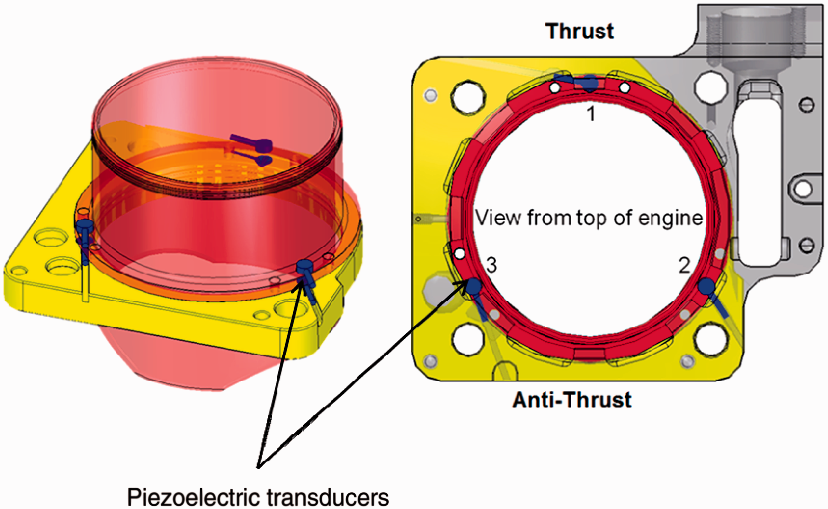
Indirect measurement of friction is routinely performed through use of net indicated mean effective pressure (NIMEP).2,3 However, the method is prone to inaccuracies. Therefore, floating liners have been developed to directly measure friction from engine test rigs. The principle of a floating liner was used by Furuhama and Sasaki, 9 based on a cylinder liner whose only connections to the bore were restricted through a set of intervening piezoelectric transducers. The inertial motion of the piston drags the liner, with the reaction measured by the transducers. The total reaction is equivalent to the net applied force on the liner due to gas pressure loading and the opposing friction. The principle of the operation and the system dynamics is fully explained by Gore et al.10,11 A brief explanation of this is provided in the next section.
The compression ring–liner conjunction is a multi-parameter variate problem where a plethora of parameters affect the regime of lubrication, thus the generated friction. There have been many predictive numerical analyses with varying degrees of complexity. The basic approach assumes good circumferential ring-bore conformance. This enables the solution of Reynolds equation (as the hydrodynamic governing equation) in one dimension with an analytical approach. Haddad and Tjan 12 show that such a simplification can be assumed with good ring-bore peripheral conformance and crucially the fitted ring’s perimeter-to-face width ratio being greater than 30 (assumed long line sliding contact). With this method other salient features such as the effect of surface topography can also be included within an analytical solution, 13 thus not resulting in long computation times. For example, Sawicki and Yu 14 provide such a solution, incorporating the effect of lubricant cavitation which affects both the load-carrying capacity and generated friction.
Morris et al. 15 provide an alternative analytical solution which makes use of average flow model representation of Reynolds equation, including the effect of surface topography in the prediction of viscous friction with the addition of boundary contribution, based on the approach of Greenwood and Tripp. 16 Morris et al. 17 and Shahmohamadi et al. 18 also included a control volume thermal mixing model to take into account the effect of lubricant shear heating as well as surface temperature of the contiguous solids (liner and the ring); the latter using a computational fluid dynamics approach. This predicts more realistic lubricant viscosity, thus generated friction. Another tribodynamic analysis including the effect of generated temperature for the high-pressure region around the top dead centre (TDC) reversal from compression to power stroke was recently provided by Mishra. 19 A combined solution of Reynolds and energy equations was made.
The engine used in the current investigation is a high-performance spark ignition single-cylinder motocross motorbike engine, which uses a single compression ring of 1.15 mm face width. The floating liner has a bore of 96 mm; thus a fully fitted ring has a perimeter of 301.1 mm, with a fitted end gap of 0.4 mm. The perimeter-to-face width ratio is in excess of 262, justifying the use of one-dimensional sliding analysis. In practice, however, the bore is out-of-round 20 although every effort is made for the current floating liner to closely approximate an idealised right circular cylindrical shape. Furthermore, the ring is subjected to variable chamber pressure loading, 21 thus in reality ring dynamic occurs,22–24 which would ideally require a lengthy two-dimensional solution such as those developed in Ma et al., 25 Bolander et al. 26 and Mishra et al.27,28 Nevertheless, for the conditions described in this paper a one-dimensional analytical solution is quite adequate and shows good conformance to the measurements. In fact, such a combined analytical-experimental approach has not hitherto been reported in literature.
It should be noted that the results in this study are for motored running conditions. For the engine used the results are applicable to fired conditions with up to 30% throttle for cold running conditions. The engine testing time for in situ measurement is also kept short, typically 15 min in order to guard against any significant rise in the liner temperature, thus enabling a reasonable comparison between the predictions based upon an isothermal analytical method and the measured results. It is also applicable to deactivated cylinders in the growing trend in the use of partially deactivated engines in urban driving conditions.
The engine test-bed
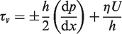
A Honda CRF 450R motocross motorcycle 4-stroke engine with the maximum speed of 11,000 r/min was chosen because of its high power and torque characteristics (41 kW, 50 Nm). The load–speed combination envelopes a wide range of engine technology. In fact, it is representative of the highest performing naturally aspirated single cylinder engine technology (i.e. over 90 kW/L and 110 Nm/L). The engine’s original engine manufacturer (OEM) barrel was replaced by a wet barrel, containing the floating liner. Due to the differential operating temperature, there is a need to control the clearance between the cylinder liner and the housing, thus minimising the induced stresses in the OEM aluminium structure. The choice of housing material was restricted to materials with a coefficient of thermal expansion between 16 and 18 ppm/K, and yield strength significantly higher than the original OEM engine barrel. Thus, austenitic stainless steel grade 304 was used for the floating liner (Figure 1). The working surface of the liner is coated with a 60 µm thick Ni–SiC layer. As shown, the floating liner is suspended in such a way that any point of contact between the liner and any rigidly mounted components are intervened by a number of piezoelectric load cells.10,11 The load cells are preloaded whilst in situ and at rest, including the weight of the liner itself. The preload value is obtained and recorded prior to any testing. Thereupon, the readings of all the load cells are set to zero prior to any testing. This means that the values obtained during any testing represent the dynamic changes only. The infinitesimal movement of the liner is such that the load cells remain perpetually in compression. The total load cell readings equate the inertial force of the liner, dragged by the motion of the piston. The net applied force is due to gas pressure loading on the upper rim of the liner, which is sealed by a labyrinth seal and liner–piston friction. Thus, depending on the sense of liner motion the friction is measured directly as
The floating liner (after Gore et al.
11
).
The engine was mounted onto an Oswald 250 kW transient dynamometer. All standard engine testing parameters (chamber pressure, air fuel ratio, test cell humidity, test cell temperature, input temperature of fuel and coolant, etc.) were logged as well as friction to ensure reliability and consistency of all measurements. The basic setup is shown in Figure 2. Further details are given by Gore et al.10,11
The engine test-bed.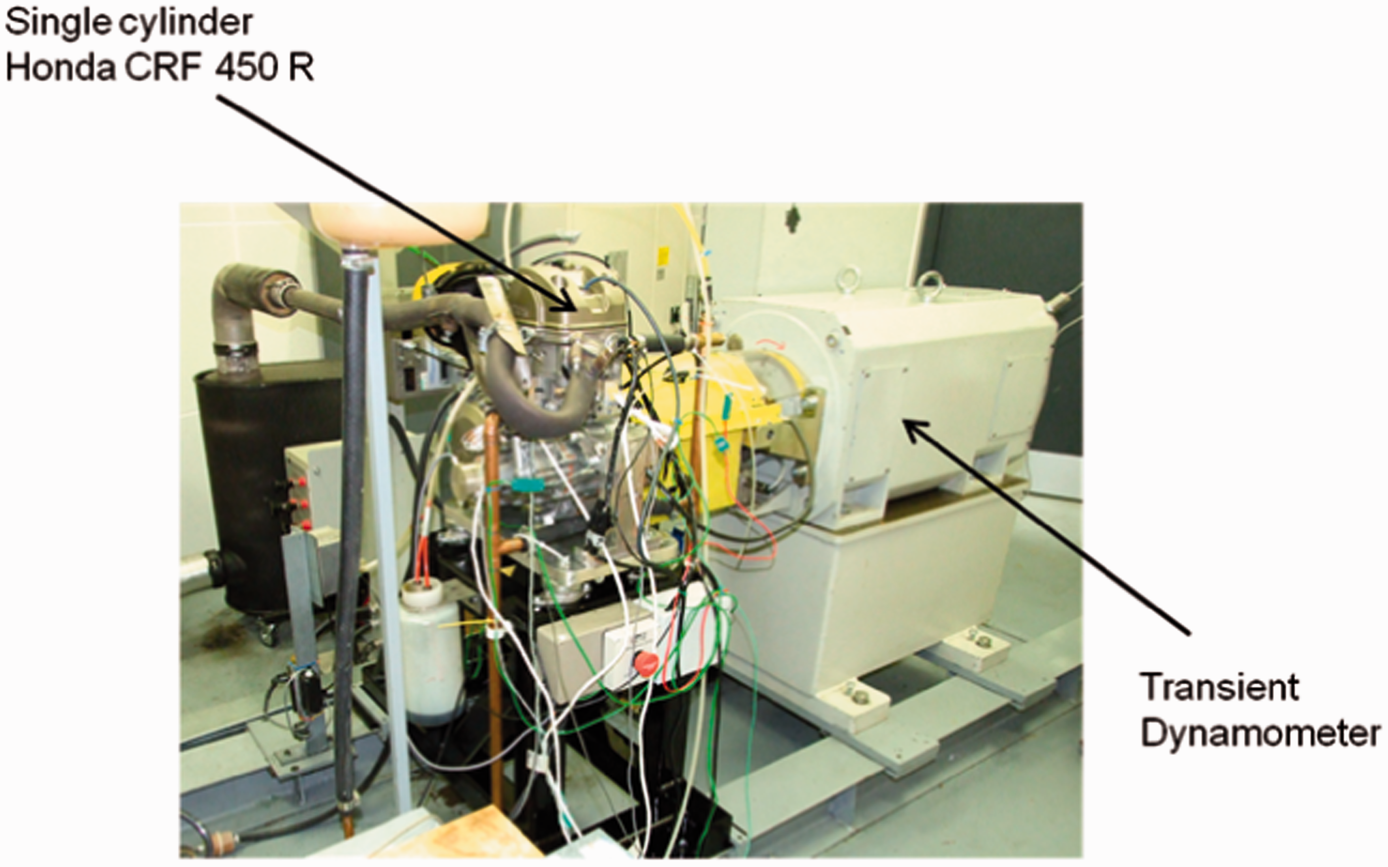
Analytical predictive method
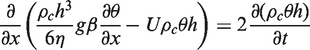
With the aforementioned assumptions of good ring–liner conformability and large ring perimeter-to-face width ratio, Reynolds equation in one-dimensional flow along the ring face width becomes
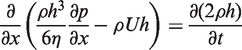
This form of Reynolds equation assumes no side leakage of the lubricant in the lateral (circumferential) direction to that of lubricant entrainment. This assumption is justified as the ring–liner conjunction enjoys a thin lubricant film.
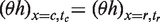
Therefore, the lubricant entrainment occurs along the ring face width, x in a domain characterised by

The parameters a, c, r and b represent the contact inlet, lubricant film rupture point (onset of cavitation region), lubricant reformation boundary and the outlet edge of the ring face width, respectively (see Figure 3). These positions demarcate regions of assumed full film, cavitation and lubricant film reformation.
Lubricant film variation within the contact domain.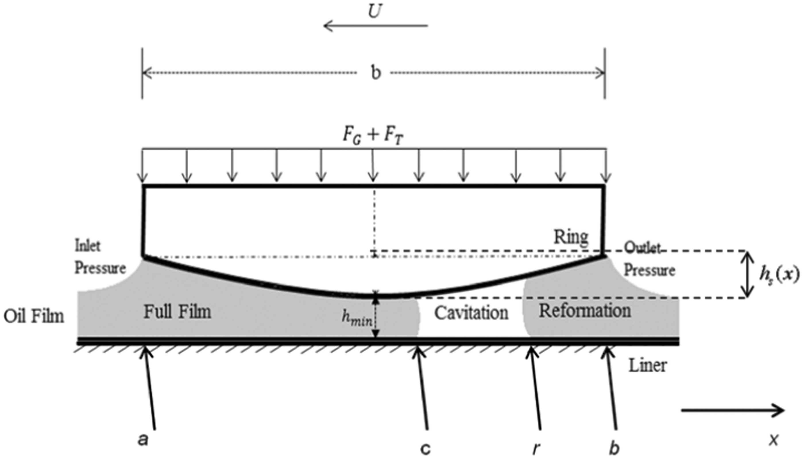
Reynolds equation has to be solved simultaneously with the film shape function in a transient manner

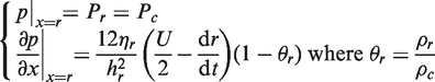
The appropriate boundary conditions for solution of Reynolds equation are
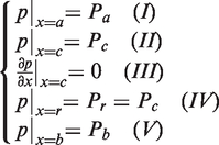
The inlet pressure Pa varies according to the sense of motion of the piston (Condition (I)). In the upstroke, it is the combustion chamber pressure, whilst in the downstroke it is the inter-ring pressure, which is considered to be the atmospheric pressure in the current study. The lubricant film ruptures at a position
The solution of Reynolds equation has to take into account three different regions in the contact domain as shown in Figure 3 as further explained below.
Region of full film
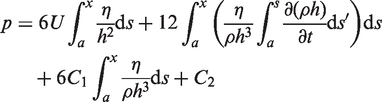
Two successive integrations of Reynolds equation with respect to x yields
Now using the boundary conditions (I) and (III) yields the integration constants
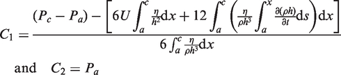
Therefore, the pressure distribution in the full film region of the contact is determined by replacing for constants of integration C1 and C2 from equation (7) into equation (6) in terms of the film rupture position
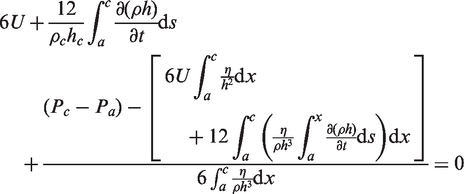
Equation (8) is solved by Newton–Raphson iterations to determine the position
The film reformation region
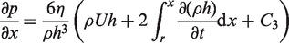
Reynolds equation (2) is doubly integrated again between the limits r and b
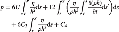
Applying the boundary conditions (IV) and (V) yields the integration constants
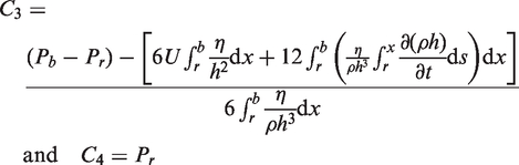
The conjunctional outlet pressure Pb depends on the sense of piston motion, in the same manner as the inlet pressure Pa. However, constant C3 can only be calculated if the film reformation position, r can be determined. For this purpose, the conditions in the cavitation region should be considered.
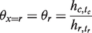
The cavitation region
In the cavitation region the pressure is assumed to be constant at the lubricant vaporisation pressure, Pc
14
with the density of lubricant being a function of pressure and its bulk modulus as
30

The ratio of density in the cavitated region to that in the full film region of the contact is defined as the film ratio,
As the result of constant pressures in the cavitation region, striated flow only proceeds in moderate to highly loaded contacts, mainly due to viscous shear (Couette flow).
31
This means that the Poiseuille (pressure-induced) flow in Reynolds equation may be neglected in this region. Therefore, Reynolds equation can be altered to the form, initially proposed by Elrod
31
in terms of θ as
And g is defined as switching term
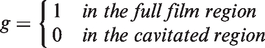
In the cavitation region with viscous shear flow only, the equation above reduces to
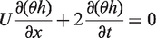
De la Cruz et al.
32
observed that the value of θ alters in the cavitation region according to the approach or separation of surfaces, as indicated by the second term in equation (16), where a negative value indicates approach of the surfaces. Equation (16) is essentially a first-order partial differential equation which can be solved using the method of characteristics. Sawicki and Yu
14
show that
At the film rupture point:
This, together with equation (14) fully describes the cavitation region of the flow. The only remaining unknown is the constant of integration C3 in equation (11), which depends on the position at the onset of film reformation. Using the boundary conditions of equation (5) in the Elrod’s equation (13), it follows that
At the start of reformation region, r, this also must equate to the pressure gradient for the reformation region in the previous sub-section, obtained as
Equating (19) and (20) and replacing for θr from equation (18) and after some basic manipulations
Replacing for C3 in equation (11) enables the evaluation of the rupture point r from the equation below using Newton–Raphson iterations
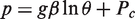
Lubricant rheology
Lubricant density and viscosity alter with pressure and temperature. The density variation with pressure and temperature in the full film region is given by Dowson and Higginson
33
and Yang et al.
34
Lubricant viscosity alters with temperature more significantly than its density in moderately loaded contacts such as the ring–bore conjunction. According to Houpert
35
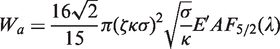
Contact load and friction
Disregarding any ring elastodynamic behaviour described by Baker et al.,
24
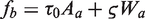
the instantaneous contact load is a quasi-static balance between the applied load to the ring and the contact reaction. The applied forces include the ring tension force, FT, which strives to return the ring to its unfitted state, as the result adhering it to the liner surface (Figure 3). Additionally, the chamber pressure acts behind the inner rim of the compression ring and acts outwards as the gas force, FG, also orthogonal to the contact surface. The summation of these forces constitutes the instantaneous applied contact load as

It is assumed that 100% of the chamber pressure acts behind the compression ring, which fully conforms circumferentially to the liner surface with the footprint contact area of

The ring tension force is

The net applied force on the ring towards the liner surface is balanced by the contact reaction, comprising the hydrodynamic load-carrying capacity as the result of generated lubricant pressures and any direct contact of surface asperities. The hydrodynamic reaction is
Note that the low pressures in the cavitation and lubricant film reformation regions do not appreciably contribute to lubricant hydrodynamic reaction.
A small area of asperity contact can occur in the compression ring–liner contact, particularly at piston dead centre reversals with low values of U, thus low entrainment flow of lubricant into the conjunction.
13
The area of asperity contact is a tiny fraction of the apparent contact area A, described above. If a Gaussian distribution of asperities is assumed, then the proportion of contact load carried by them may be obtained, using Greenwood and Tripp
16
approach, where the asperity contact area and their share of carried load respectively become
The statistical functions
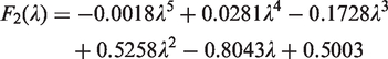
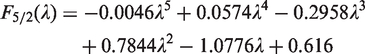
It is noteworthy that the usual cylinder liner configuration is cross-hatch honed. In such cases, the surface topography does not follow a Gaussian distribution of asperities as it forms a plateau. This makes a comparison between analytical predictions and measured results quite complicated. Therefore, for the case of the floating liner in this study a super-finished liner surface is made. For the usual cross-hatched liners the height of the plateau
The total contact reaction is, therefore

As already mentioned, there are two contributing sources to conjunctional friction: Firstly, the reported literature shows that for most of the engine cycle, the dominant mechanism of friction is viscous shear of the lubricant. Secondly, in the regions of piston motion with low sliding velocity (at or in the vicinity of motion reversals) there is lack of sufficient lubricant entrainment into the contact conjunction (low value of U). In these locations two other sources of friction play an important role. One is due to the direct contact of counterface surface asperities (boundary lubrication). The combination of boundary and viscous friction leads to a mixed regime of lubrication. The other mechanism is pressure-induced viscous shear (Poiseuille shear), which occurs with a rise in pressure gradient across the conjunction (dp/dx). This can occur at piston reversals, particularly at the top dead centre and in transition from the compression stroke to the power stroke. All these sources of friction should be taken into account. For lubricant contributions
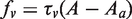
The contribution due to asperity interactions occurs over the area of asperity peaks Aa. There are two contributions in this case: One is due to adhesive friction of cold welded asperities under localised pressure which is shown by the second term on the right-hand side of equation (38). Here, the coefficient of asperity shear strength, ς is analogous to the coefficient of friction at the asperity-level contact and is usually measured through use of atomic force microscopy (AFM) in contact mode.38,39 The second contribution is the first term in equation (38), which is based on the assumption that an ultra-thin film of lubricant is adsorbed to the asperity tips and undergoes non-Newtonian shear at its limiting Eyring shear stress, τ0.
40
The asperity contacts can also cause elasto-plastic deformation, which affect boundary friction. These are not taken into account, but are indirectly accounted for by the direct measurement of ς. The value of ς corresponds to the coating of the cylinder liner which is Ni–SiC. This is obtained through use of an AFM, operating in lateral force mode as fully described by Styles et al.38,39 More comprehensive models for asperity level friction have recently been developed.41,42
Finally, the total friction is

Therefore, the predicted and measured frictions from equations (1) and (39) can be compared.
Solution method
The following solution procedure is followed:
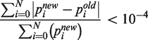
Step 1: At the initial crank angle (time), an initial value for the hydrodynamic pressure distribution enables calculation of the corresponding rheological parameters from ‘Lubricant rheology’ section. In addition, an initial value for the minimum film thickness, hmin and squeeze film velocity dh/dt, is assumed. These values are subsequently altered during the iteration process. Step 2: The pressure distribution is calculated (‘Analytical predictive method’ section). Step 3: The rheological properties of lubricant are updated based on the pressure distribution from Step 2. This step is repeated until the following convergence criterion is met Step 4: The final hydrodynamic pressure distribution is integrated over the entire contact area (equation (30)). The asperity load support is also calculated from equation (32). Step 5: The instantaneous applied contact load is obtained from equations (26) to (29). Step 6: Instantaneous quasi-static equilibrium at a given crank angle demands that the following convergence criterion is satisfied
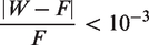
Otherwise, a new minimum film thickness value is calculated from
Then, Steps 2 to 6 are repeated until the condition (41) above is satisfied.
The calculation process continues until a periodic minimum film thickness variation is achieved for the whole engine cycle.
Results and discussion
In practice, it is difficult to isolate the frictional losses from a particular conjunction (such as that of the compression ring–liner contact) in an IC engine.
Firstly, unlike multi-cylinder configuration, in single cylinders the contribution to frictional losses is quite significant in the case of engine bearings. 43 Consequently, the single cylinder engine used in this investigation uses rolling element bearings as its big-end bearing, which significantly reduces the generated friction when compared with the usual elliptic bore journal bearing. This is another reason for the choice of Honda CRF 450R engine for this study.
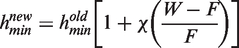
Secondly, direct measurement of in situ friction requires a floating liner, described in The Engine Test-bed Section. A somewhat over-sized piston, providing a nominal clearance of 50 µm was specifically produced in order to be able to remove the top compression ring and measure friction of the piston skirt and oil control ring assembly alone under motored conditions. Such a test is not possible under fired conditions. The difference between the friction of full piston assembly (with the compression ring included) and that without it, is assumed to yield the frictional contribution of the compression ring. Fortunately, with the Honda CRF 450R, the chamber pressure reaches a maximum value of 20 bar at the top dead centre without cylinder firing (Figure 4). This is quite representative of chamber pressure for fired condition at 30% throttle at the same engine speed of 3000 r/min. This has the added advantage of eliminating other phenomena under fired conditions, such as piston and liner thermo-elastic distortion. Therefore, the motorised testing in line with the above stated conditions reported here can also provide representative conditions for fired engine conditions at cold start-up.
Cylinder chamber pressure for motored engine at 3000 r/min.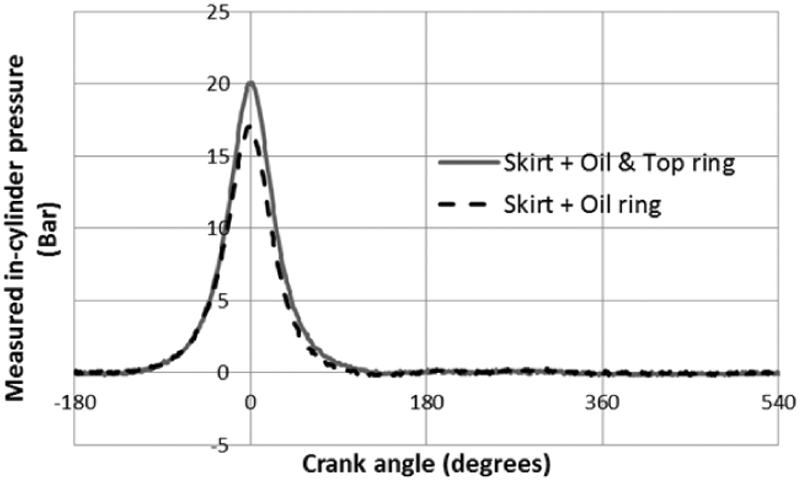
List of engine specifications and employed data.
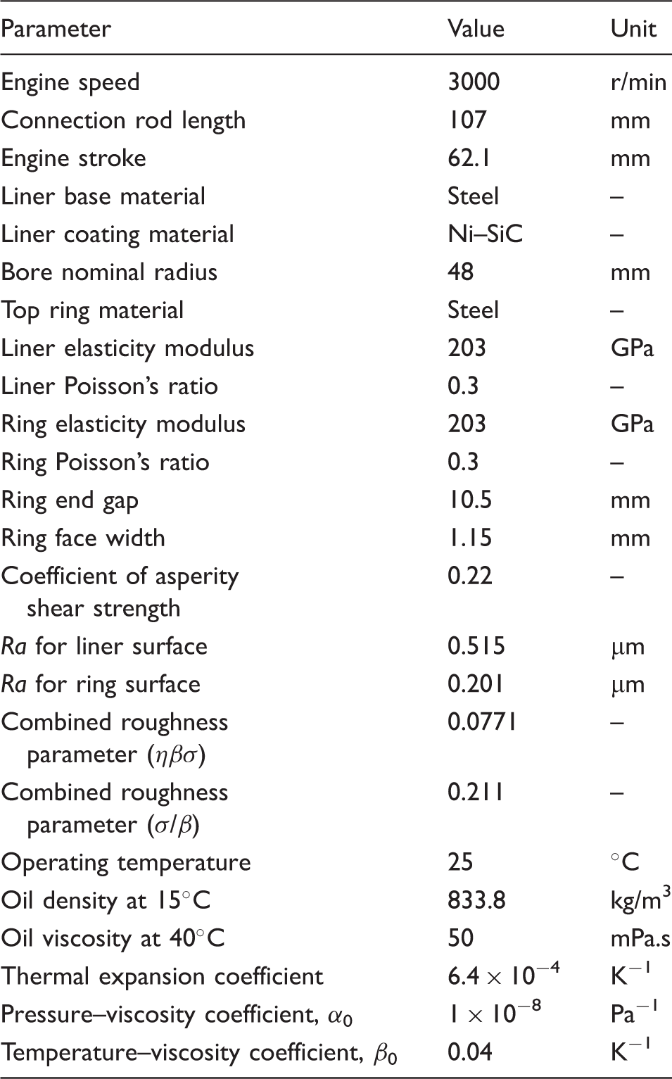
Figure 5(a) shows the measured friction using the floating liner’s piezo-electric transducers, chamber pressure curves in Figure 4 and equation (1). The changes of sign in friction represent piston reversals. The gap between the two traces can be attributed to the frictional contribution of the compression ring. The results show that the main contribution to friction in the case of this engine set up and running conditions is due to the piston skirt and oil ring. For the test conditions reported here (Table 1), the compression ring friction contribution is approximately 10–15% of the total (Figure 5). Since the conditions with or without the compression ring in place are not identical (e.g. different in-cylinder pressures) and there is a certain amount of noise resident on the friction traces, the signals cannot reliably be subtracted.
Comparison of measured and predicted ring–liner friction.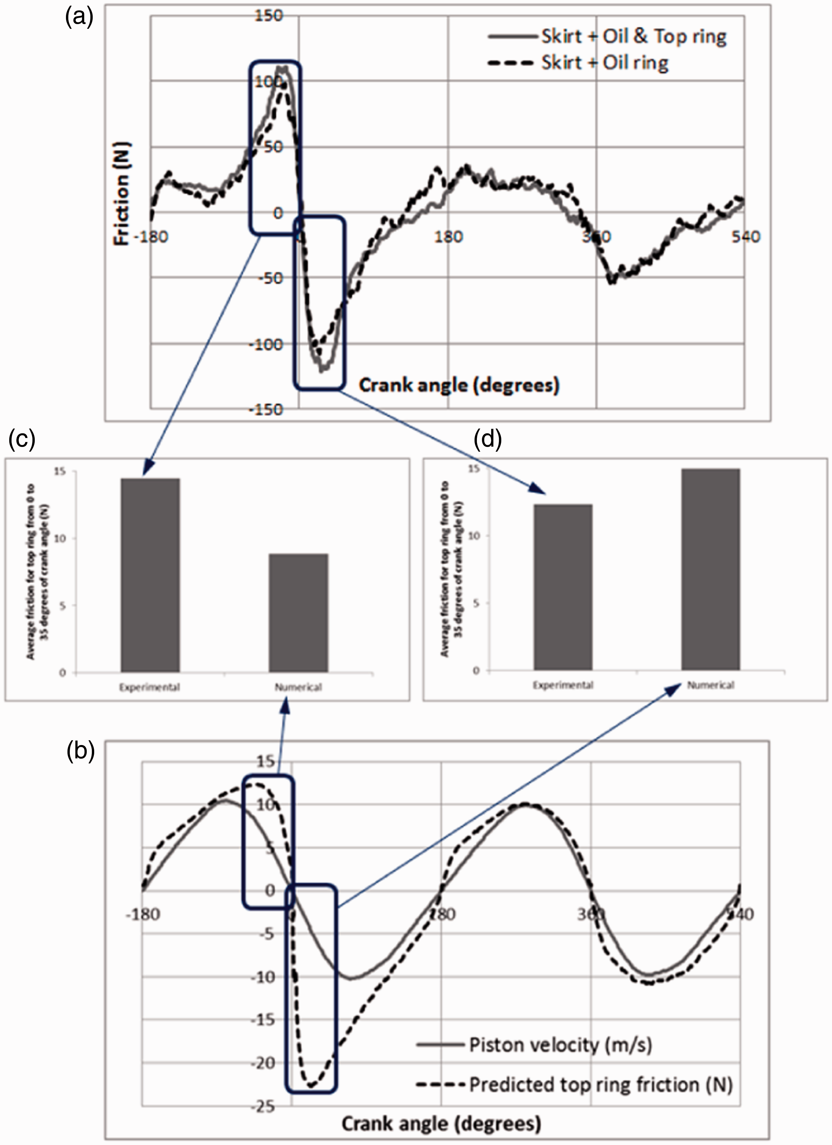
Figure 5(b) shows the predicted friction during an engine cycle under the same conditions as those in Figure 5(a). The variations in the sliding velocity are also shown in the figure. The first thing to note is that friction variation is directly proportional to the sliding velocity (i.e. Variations of minimum film thickness for one engine cycle.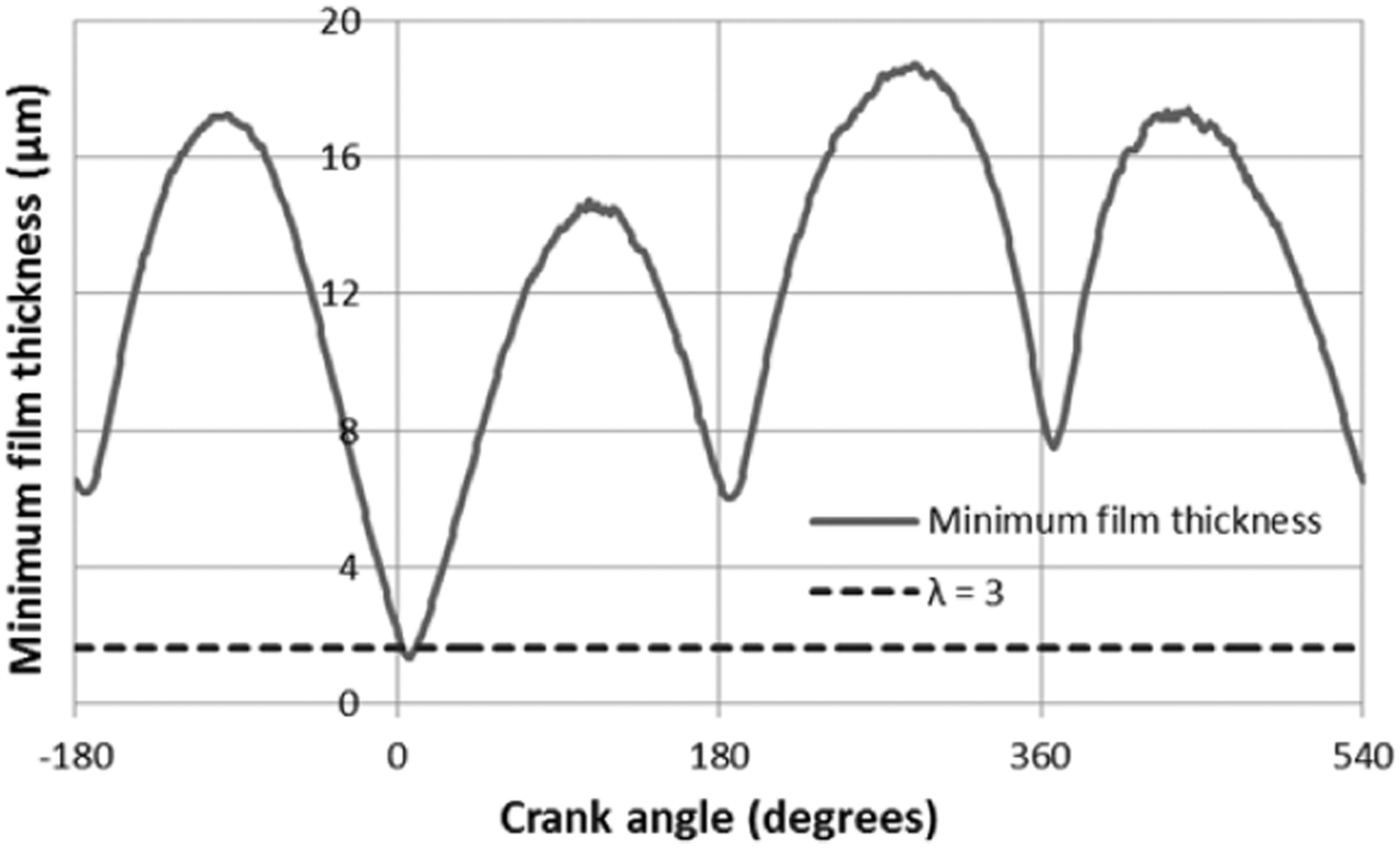
Figure 5(c) and (d) shows the compression ring–liner friction contributions in two regions. One region is in the compression part of the cycle, prior to the TDC reversal at the crank angle of 0° and the other is in the early stages of the expansion stroke, past the same TDC reversal. An average value for each region is calculated from measurements and predictions. These are shown in Figure 5(c) and (d).
Reasonably good agreement is demonstrated. However, there are some residual differences which can be attributed to many causes. These may include some of the assumptions of the analytical method used, such as ring–liner circumferential conformity, ignoring the piston (and ring) dynamics, assumed isothermal conditions and/or a fully flooded conjunctional inlet. Although the engine is motored and the test duration does not exceed 15 min, the viscous shear of the lubricant can promote a rise in its temperature and that of the adjacent solid boundaries. Therefore, the isothermal analysis here can lead to a certain degree of error. Furthermore, in practice a fully flooded inlet in the upstroke sense of the engine is not likely, and such an assumption can be regarded as idealised. On the experimental side the presented results are average of many cycles, where there are small variations (1–2%) in chamber pressure. In addition, the position of TDC reversals can alter from cycle to cycle, this being a characteristic of inherently unbalanced single cylinder engines. 29 Nevertheless, there is generally good overall agreement between measurements and predictions.
Conclusions
The paper presents direct in situ measurement of in-cylinder friction using a devised floating liner system. With a slightly over-sized piston, it was possible to remove the compression ring in the single cylinder motocross motor-cycle engine. The difference in the cyclic frictional traces with and without the presence of the compression ring provided an assessment of in-cycle friction contributed by the compression ring. An analytical predictive method, based on Elrod’s modification to Reynolds equation, taking into account the effect of film reformation is also presented. The predicted viscous friction using this approach, supplemented by boundary friction as the result of any asperity interactions has shown reasonable agreement with the measurements. Both predictions and measurements show that the contribution of compression ring is most significant in the high pressure part of the engine cycle and at top centre reversal between compression and expansion strokes. This indicates that the compression ring complies with its primary sealing function. Viscous friction of the lubricant dominates under the tested and simulated isothermal motored conditions. This in fact is representative of idle to low-speed cycling in creeping traffic with a cold engine (conditions which typically form a part of steady-state New European Drive Cycle (NEDC) for emission testing). In addition, the conditions also replicate that of a deactivated cylinder in engines using CDA. The next stage of this research is to include the thermal effects in the analysis and undertake measurement and simulation for steady-state hot engine cycle at simulated low crawling speeds (another part of the NEDC). It is anticipated that boundary friction would play a more significant role under such conditions.
Footnotes
Declaration of Conflicting Interests
The author(s) declared no potential conflicts of interest with respect to the research, authorship, and/or publication of this article.
Funding
The author(s) disclosed receipt of the following financial support for the research, authorship, and/or publication of this article: The authors would like to express their gratitude to the Engineering and Physical Sciences Research Council (EPSRC) for the sponsorship of this research under the Encyclopaedic Program Grant (![]() ).
).