
Abstract
The aggregation method for designing light-weight structures consists of consolidating multiple loaded elements into fewer elements with larger cross-sections under the same total load. This approach is very effective for beams with arbitrary cross-sectional shapes and leads to a significant reduction in the material required to support a given total load. For instance, in a five-to-one aggregation, the material usage is reduced by a factor of 1.71. The theoretical foundations of the method of aggregation have been rigorously developed and proven, specifically for structures composed of beams with arbitrary cross sections. Additionally, finite element simulations and experimental testing on statically indeterminate structures validated the method and confirmed its effectiveness. These investigations demonstrated that aggregating loaded elements substantially increases load-bearing capacity while reducing material consumption. It has also been established that segmenting multiple loaded beams into a larger number of beams, under the same total load, increases the total elastic strain energy of the structure. This result holds true for arbitrary cross-sectional shapes. Finally, an interpolation method has been proposed for reducing the total volume of material at a specified maximum von-Mises stress and maximum deflection.
Keywords
Introduction
Design optimisation is widely applied in mechanical and structural engineering to identify optimal design solutions by simultaneously considering multiple objectives.1–3 This approach evaluates various criteria, such as strength, durability, weight, cost and performance, under specific physical, geometric, material, and economic constraints.
Multi-objective optimisation methods, for example, can generally be classified into two categories: classical and evolutionary. Classical methods typically aim to identify a single optimal solution, often through techniques such as weighted sums or constraint handling. In contrast, evolutionary methods, such as genetic algorithms and particle swarm optimisation, employ population-based search strategies to generate a diverse set of Pareto-optimal solutions, offering trade-offs among competing objectives. Ultimately, this optimisation framework supports the development of more balanced, efficient, and robust mechanical designs that better address the diverse requirements of customers and environmental considerations.
Design optimisation oriented towards the optimisation of the shape of components is the topology optimisation, originally developed as a mainstream design technique for achieving lightweight structures. In recent years, it has been widely applied to create efficient, lightweight designs.4–7 Various topology optimisation approaches have emerged, including the evolutionary structural optimisation method, the density method and the level set method. 4
Recent advancements in manufacturing technologies, particularly additive manufacturing (3D printing)7–9 and advanced metal forming techniques, 10 have significantly expanded the possibilities for implementing topology optimisation. Additive manufacturing enables the fabrication of complex, optimised geometries that are difficult or impossible to achieve with traditional manufacturing methods. It also facilitates the integration of multiple functions into a single component, improving load-bearing capacity while maintaining or reducing overall weight.
The combination of materials in structural components has also been leveraged to create composite beams with enhanced flexural strength, often surpassing that of the individual constituents. 11 Notable examples include beams made from glass fibre- and carbon fibre-reinforced composites, steel-reinforced concrete and sandwich structures. In sandwich beams, for instance, the principle of functional separation is employed: strong materials are placed away from the neutral axis to resist most of the load, while lightweight, low-strength materials near the neutral axis provide structural stability.11–13
Aggregation techniques have already been applied in certain structural designs, where steel plates are welded together to form reinforced beams, thereby increasing the overall load-carrying capacity by enabling the beam to resist higher bending moments and shear forces. 14 The structural behaviour of aggregated steel box beams filled with concrete has also been investigated. 15
In this paper, we introduce a different concept of aggregation: the consolidation of multiple structural components, made of the same material, into fewer elements with larger, geometrically similar cross-sections.
For loaded components with arbitrarily shaped cross-sections, the potential of aggregation and segmentation for optimising load capacity remains largely unexplored. Although multiple loaded elements are commonly used in engineering and construction, the stress analysis literature lacks focused studies on the implications of aggregation and segmentation.13,16–20 This is a surprising omission, given the conceptual simplicity and practical relevance of aggregation.
Moreover, structural engineering textbooks21–23 and studies on the optimisation of loaded beams24,25 do not address this concept. Similarly, the structural reliability literature offers no discussion on the topic.26,27
This absence of discourse on the aggregation and segmentation of components with arbitrary cross-sections reveals a significant knowledge gap and underscores the need for further research in this area.
We emphasise that the proposed aggregation method represents a fundamentally different approach from standard topology optimisation. It has been developed independently, without relying on any topology optimisation algorithms.
Topology optimisation typically involves significant computational overhead due to the large number of iterative simulations required. In contrast, the aggregation method introduced here avoids iterative procedures entirely and involves minimal computational cost. Moreover, unlike topology optimisation, the performance of the proposed method is not influenced by the size of the individual components comprising the structure.
Traditional manufacturing techniques such as casting, forging and machining, often struggle to accommodate the intricate geometries produced by topology optimisation. These complex shapes may also introduce stress concentration zones, which can lead to premature fatigue failure. The proposed aggregation method does not suffer from these drawbacks. In fact, it offers substantial weight savings, making it a highly efficient and practical alternative for structural design optimisation.
Bending, or flexural loading, is among the most common loading conditions encountered in engineering structures. Elements with enhanced bending capacity are less prone to premature failure or fatigue due to overloading or dynamic loading, resulting in extended service life, lower maintenance requirements and improved safety.
Accordingly, this study aims to explore the effectiveness of the aggregation method through theoretical analysis, computational simulations, and experimental testing with physical prototypes. The specific objectives are as follows:
(i) To provide a theoretical foundation for the aggregation method for load-carrying elements with arbitrarily shaped cross-sections;
(ii) To compare the material needed for supporting a given total load between aggregated and non-aggregated structures with arbitrarily shaped cross-sections;
(iii) To compare the load-carrying capacities of aggregated and non-aggregated structures constructed with the same total volume of material;
(iv) To evaluate the impact of segmentation on the accumulated elastic energy.
The findings from these investigations constitute the primary contributions of this paper and offer direct implications for structural design, particularly in enhancing load capacity and reducing the risk of failure in structures subjected to bending.
Impact of aggregation and segmentation on critical properties of structures
Consider a non-aggregated and aggregated structure. The non-aggregated structure is composed of on n load-carrying elements while the aggregated structure is composed of a smaller number m of load-carrying elements (m < n). The cross sections of the aggregated and non-aggregated structure are geometrically similar, with a coefficient of proportionality p > 1 relating the geometrical dimensions of the non-aggregated and aggregated elements. Let both the non-aggregated and aggregated structure be subjected to the same total load P. Then, the load per loaded element in the non-aggregated structure is P/n while the load per element in the aggregated structure is P/m.
Segmentation is the opposite process to aggregation and is defined in a similar fashion: a number m of loaded elements are segmented into a larger number n of loaded elements with geometrically similar cross sections (m < n).
Suppose that
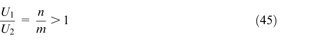
As it will be demonstrated later, most of these critical quantities can be summaries by the equations:
where

where
Let us denote
Theoretical justification of the aggregation method as a design optimisation method reducing the weight of structures
Let the stress permitted by the material be
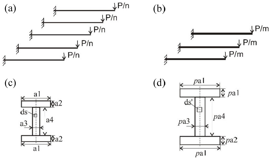
(a) Non-aggregated structure built on n cantilever beams, (b) aggregated structure built on m cantilever beams (m < n), (c) a beam cross section from the non-aggregated structure and (d) a geometrically similar beam cross-section from the aggregated structure.
The beams cross-sections from the non-aggregated and aggregated structure are with arbitrary shape and geometrically similar, with a coefficient of proportionality p > 1 (scaling factor) between the corresponding dimensions (see the example in Figure 1(c) and (d)). For the sake of simplicity in presenting the relevant theory, a uniform cross section is assumed along the length of the beam.
Let


where
For a bending moment M acting on a cantilever beam, the maximum tensile stress in the beam is determined from the classical formula:
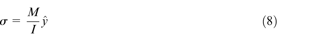
In equation (8), I denotes the second moment of area of the cross-section and

exists. The loading moment
Now, following the definition of a second moment of area, let
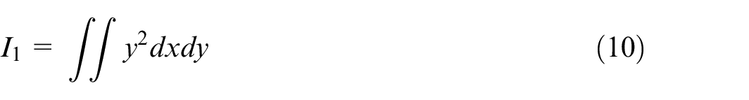
be the second moment of area for the non-aggregated sections (Figure 1(c)), where y is the distance of the infinitesimally small area
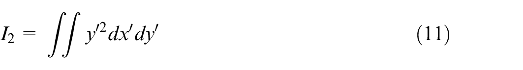
where
As a result,
of the aggregated and non-aggregated cross-sections.
For a non-aggregated beam, equation (8) gives:
while for an aggregated beam, equation (8) gives
Taking the ratio of (14) and (15) results in
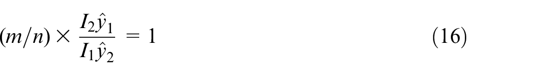
Substituting (9) and (13) in (16) results in

from which:

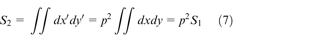
The total volume of the non-aggregated structure is
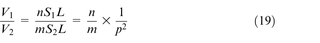
Substituting (18) in (19) finally gives:
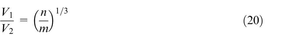
This completes the proof of assertion (5) of Theorem 1.
Note that considering (18), we also have:
In words, the ratio of the volumes necessary to support the total load, in the non-aggregated and aggregated structure, is equal to the scaling factor relating the dimensions of the geometrically similar cross sections.
For n-to-one aggregation (m = 1), from equation (20), it follows that
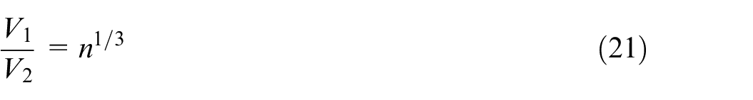
Figure 2 presents the volume of material reduction factor for n = 2,3,4 and 5. As can be seen from Figure 2, the reduction of material needed to support the same specified total load is impressive. For five-to-one aggregation, for example, the reduction in material used is 1.71 times!
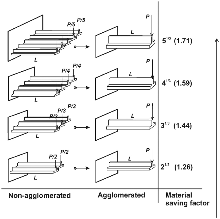
Material reduction factor for n-to-1 aggregation (n = 2,3,4,5). The aggregated and non-aggregated structures carry the same total load P.
From the classical stress analysis theory,13,16 for the deflection at the free end of the non-aggregated cantilever beams, the value

is obtained and for the deflection at the free end of the aggregated cantilever beam, the value
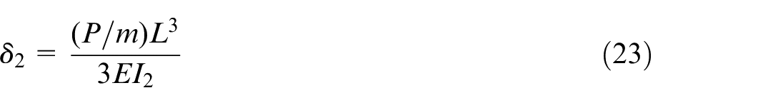
is obtained, where E is the Young’s modulus of the material of the beams.
Now, from expression (13), for the ratio of the second moments of area of the aggregated and non-aggregated cross-sections, the following expression is obtained:

The ratio of the maximum deflections in the non-aggregated and aggregated structure is obtained by dividing equations (22) and (23):
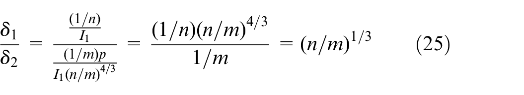
This completes the proof of assertion (6) in Theorem 1.
Note that considering (18), we also have:
In words, the ratio of the maximum deflections in the non-aggregated and aggregated structure is equal to the scaling factor linking the dimensions of the geometrically similar cross sections.
The same analysis and the same results (20) and (25) are also obtained for simply supported beams and to conserve space details related to the proof have been omitted.
Improving the load capacity at a constant amount of material
Suppose that the non-aggregated structure in Figure 1(a) includes n identical beams with arbitrary shape of the cross section while the aggregated structure in Figure 1(b) includes fewer number m of identical beams (m < n).
The beams from the non-aggregated and aggregated structure have geometrically similar cross sections, with a coefficient of proportionality p > 1 linking the corresponding dimensions (see the example in Figure 1(c) and (d)). The coefficient of proportionality p has been selected such that the total volume of the non-aggregated structure is equal to the total volume of the aggregated structure.
Let


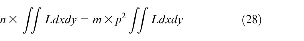
From the condition of equivalence of volumes (28), after cancelling

From equation (13),

From the classical bending theory, for the tensile stress at the fixed support of the non-aggregated cantilever beam, the value:
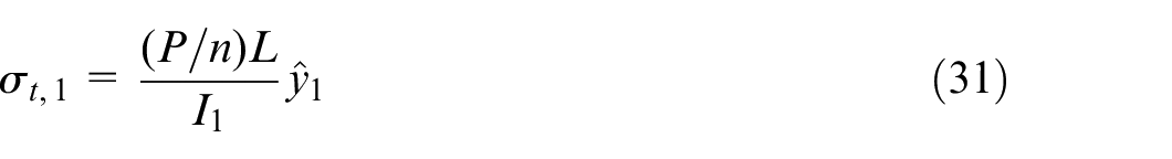
is obtained while for the aggregated beam, the value
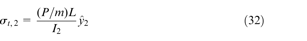
is obtained, where
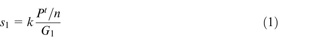
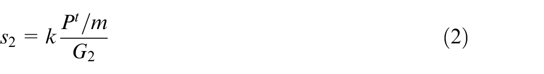
Equations (31) and (32) are special cases of equations (1) and (2), where
Because of the geometric similarity, for the largest distances from the neutral axis

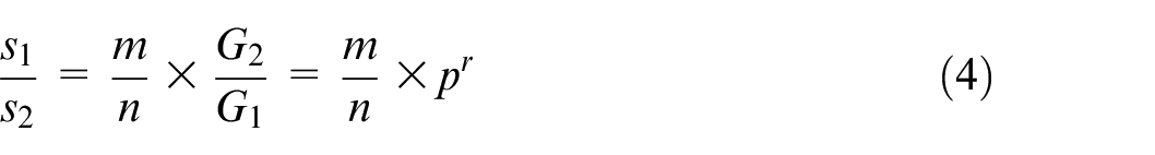
holds. The ratio of the maximum tensile stresses in the non-aggregated and aggregated structure is obtained by dividing equations (31) and (32):
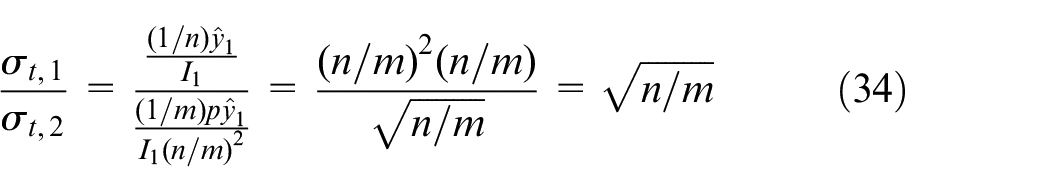
Note that for the maximum tensile stresses, considering (29), we also have:
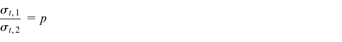
In words, the ratio of the maximum tensile stresses in the non-aggregated and aggregated structure is equal to the scaling factor linking the dimensions of the geometrically similar cross sections.
For the maximum deflection of the non-aggregated cantilever beams, the value
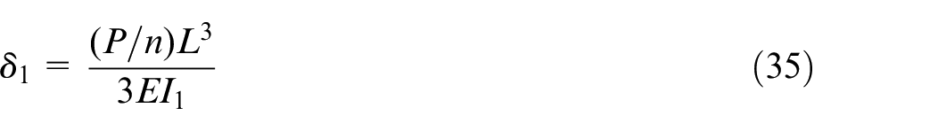
is obtained from the standard bending theory and for the maximum deflection of the aggregated cantilever beam, the value
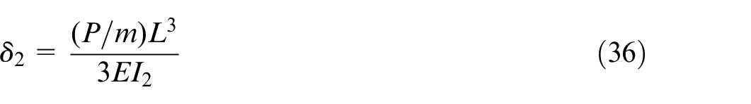
is obtained, where E is the Young’s modulus of the material of the beams.
Equations (35) and (36) are also special cases of the general equations (1) and (2), where
The ratio of the maximum deflections in the non-aggregated and aggregated structure is obtained by dividing the equations (35) and (36):
This completes the proof of assertions (26) and (27) of Theorem 2.
Note that for the maximum tensile stresses, considering (29), we also have:
In words, the ratio of the maximum deflections in the non-aggregated and aggregated structure is equal to the square of the scaling factor linking the dimensions of the geometrically similar cross sections.
In addition, the aggregated structure has a significantly smaller total surface area along the length L compared to that of the non-aggregated structure. Because the coefficient of proportionality of the linear parameters is

exists.
The ratio
Since
Finally, another advantage of the aggregated structure over the non-aggregated one is the smaller number of connection points (anchors) during assembly.
The same analysis and the same results (34), (37) and (39) are also obtained for simply supported beams and to conserve space, details related to the proof have been omitted.
We need to point out that a further increase in load-carrying capacity could have been achieved by tapering the cantilevered beam, which is a textbook approach to enhancing load capacity by increasing thickness at the fixed end and gradually decreasing it towards the free end. For a given total material volume, this tapered shape improves load-bearing efficiency. However, for the sake of simplicity in presenting the underlying theory, a uniform cross-section along the beam’s length was intentionally chosen to simplify the theoretical exposition of the aggregation method.
This choice in no way diminishes the advantages of the proposed method. As can be verified from Figure 2, even with a uniform cross-section, the material savings required to support the same total load are significant. For example, with a five-to-one aggregation, material usage is reduced by a factor of 1.71.
Aggregation must be applied judiciously, considering structural redundancy and operational conditions. For example, if a structure with four supporting elements must remain functional after the failure of one, a 4-to-2 aggregation may be unsuitable. However, by no means does aggregation promote structural collapse. In fact, an aggregated structure exhibits significantly increased load-bearing capacity and a much larger margin of safety than its non-aggregated counterpart. Additionally, aggregation does not necessarily imply leaving larger gaps between structural elements.
Segmentation as a design technique that increases the elastic strain energy stored in the structure
Let the aggregated structure, composed of m uniformly loaded beams, be segmented into a structure composed of n uniformly loaded beams (n > m). It is assumed that the same total volume of material has been used for the non-aggregated and the aggregated structure. The elastic strain energy U stored in a cantilever beam, loaded by a concentrated force with magnitude
where I is the second moment of area of the beam and E is the Young’s modulus. The total load P is assumed to be the same for both the aggregated and the segmented structure. The stored elastic strain energy
The total elastic strain energy, stored in the segmented structure, is therefore given by
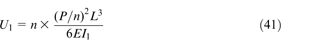
while the total elastic strain energy stored in the aggregated structure is given by
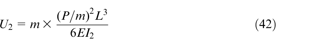
Again, equations (41) and (42) are special cases of equations (1) and (2), where
It will be shown that the inequality
From equations (41) and (42), taking the ratio
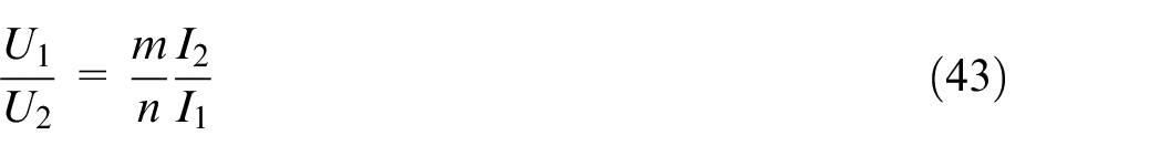
From equations (29) and (30), for equal volumes of material of the non-aggregated and aggregated structure, equation (43) becomes
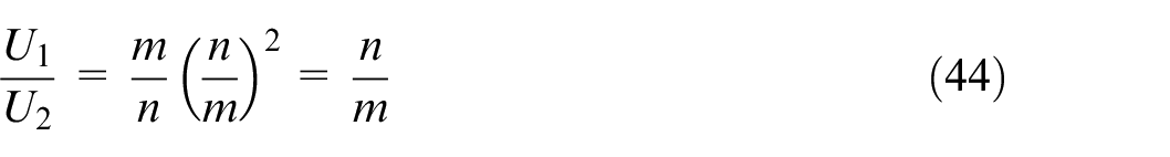
Since n > m, the ratio
Inequality (45) shows that segmenting a beam structure increases the elastic strain energy stored in the structure.
Consider segmenting a structure containing
The same conclusion can also be reached for simply supported beams. To avoid repetition, the argument related to simply supported beams has been omitted.
Testing the aggregation method using finite element analysis
The verification of the aggregation method was conducted using steel beams having a Young’s modulus of 200 GPa and a Poisson’s ratio of 0.3, subjected to 8-to-2 aggregation. The structures were composed of cantilevered beams and statically indetermined
Testing the aggregation method on cantilevered beams
One of the ends of the cantilevered beam is fixed, while the other end is free (Figure 3). The distance between the fixed support and the end of the beam is L = 100 mm for both the non-aggregated and aggregated structures.
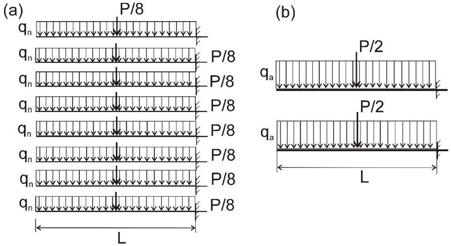
Testing the aggregation method on cantilevered I-beams: (a) non-aggregated beams and (b) aggregated beams.
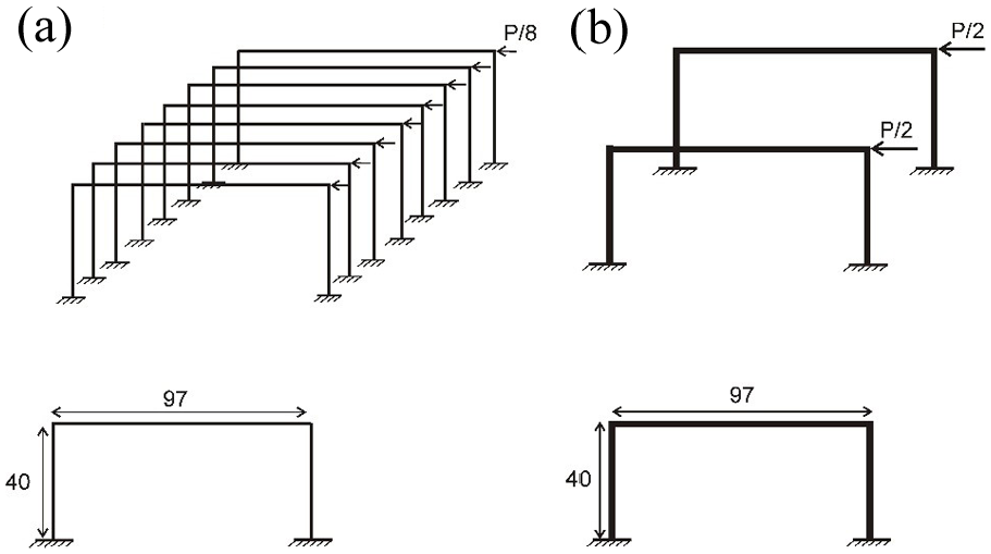
The cross sections of the non-aggregated and aggregated beams are according to Figure 4. The dimensions of the cross-sections have been selected so that the total volume of material in eight non-aggregated beams (Figure 3a) is exactly equal to the total volume of material in two aggregated beams (Figure 3b).
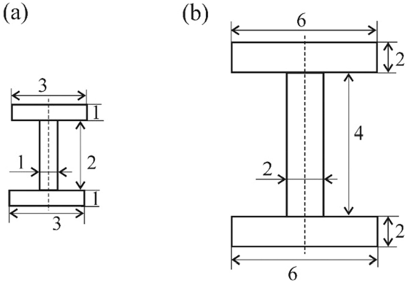
Cross sections of the (a) non-aggregated and (b) aggregated I-beams.
The same total load P = 360 N has been applied to both the aggregated and non-aggregated structure. As a result, each beam from the non-aggregated structure in Figure 4(a) (8 beams) is loaded with a force of 360/8 = 45 N, distributed uniformly along the top surface of the beam. Each beam of the aggregated structure (2 beams) is loaded with a force of 360/2 = 180 N (8 × 45 N = 2 × 180 N = 360 N), distributed uniformly along the top surface of the beam.
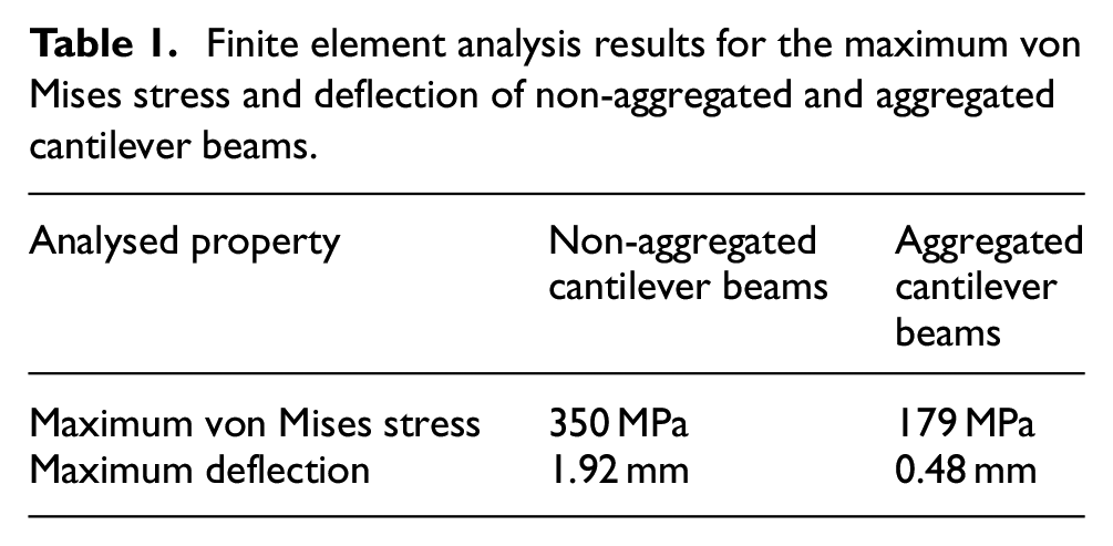
Table 1 lists the maximum von Mises stress and the maximum deflection characterising non-aggregated and aggregated cantilever beams. From the table, it can be concluded that for the same total applied load (360 N), the aggregated structure experiences a significantly smaller maximum von Mises stress and maximum deflection compared to the non-aggregated structure.
Finite element analysis results for the maximum von Mises stress and deflection of non-aggregated and aggregated cantilever beams.
Testing the aggregation method on statically indeterminate
-frames
Testing of the aggregation method was also conducted on centrally loaded and side loaded statically indeterminate
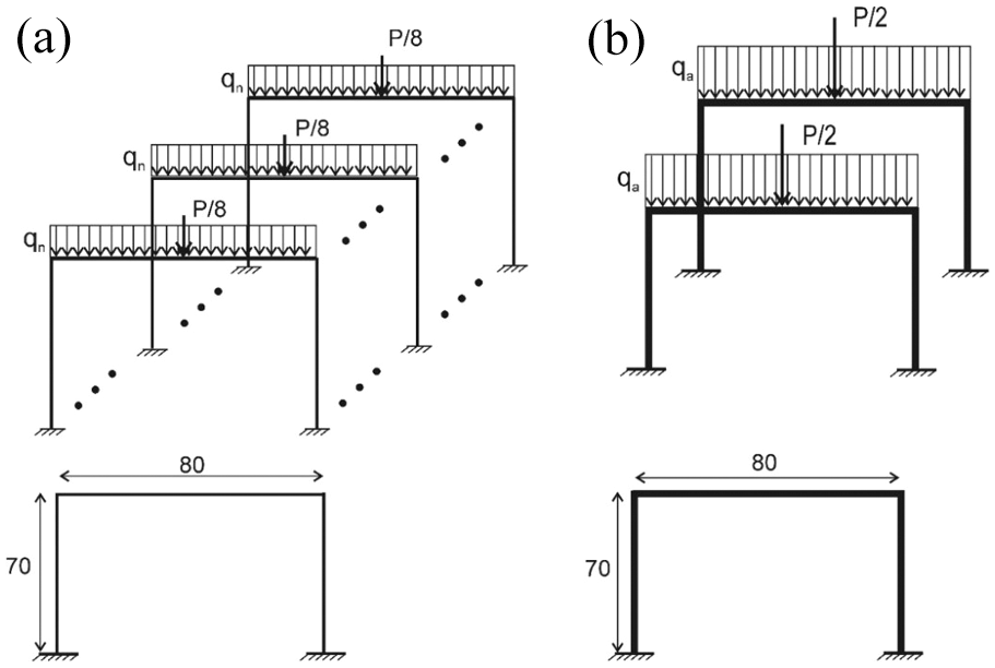
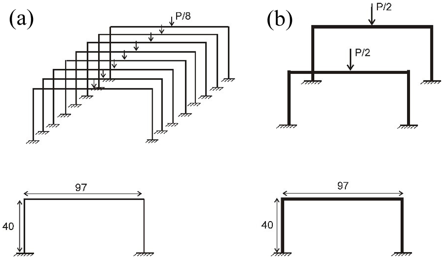
Eight-to-two aggregation of centrally loaded
The load applied on an individual aggregated
The maximum von Mises stresses and deflections of the
Results for the maximum von Mises stress and maximum deflection for centrally loaded non-aggregated and aggregated
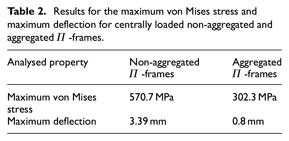
The maximum von Mises stress for the aggregated
Testing of the aggregated method was also conducted on a side-loaded statically indeterminate
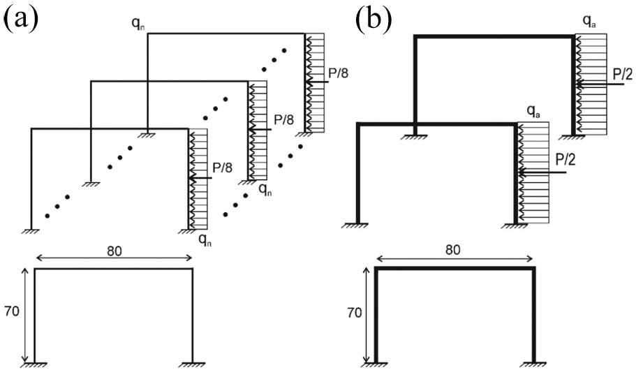
Eight-to-two aggregation of side-loaded
The load applied on an individual aggregated
The maximum von Mises stresses and deflections of the side-loaded
Results for the maximum von Mises stress and maximum deflection for side-loaded non-aggregated and aggregated
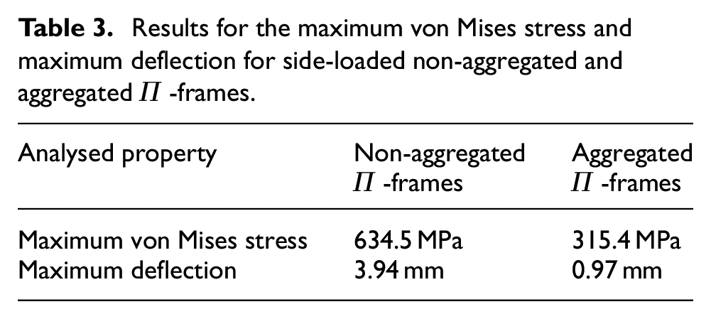
The simulation studies involving statically indeterminate structures demonstrated that for statically indeterminate frames, aggregation also had a dramatic effect on their load capacity.
Reducing the total volume of material at a specified maximum von-Mises stress and maximum deflection
Tables 2 and 3 show that, for the same material volume, the aggregated structure exhibits significantly reduced stress and deflection. This offers the potential to decrease the cross-sectional area and substantially reduce the material volume, while maintaining the maximum von Mises stress and deflection within acceptable limits.
In design, both the maximum von Mises stress and the maximum deflection are critical parameters. When the total load is constant for both the non-aggregated and aggregated structures, the scaling factor can be adjusted to ensure that the von Mises stress and deflection remain below specified thresholds, while simultaneously achieving a notable reduction in material volume. The scaling factors ps* and pd*, which correspond to specific maximum permissiblevon Mises stress and deflection values, can be determined through interpolation. This process typically requires only a small number of finite element analysis simulations.
The interpolation method for determining the optimal scaling factor p* involves conducting a series of simulation experiments on an aggregated element at different scaling factor values (p1,p2,p3,p4,p5; see Figure 7a). These experiments provide a relationship between the scaling factor and the maximum von Mises stress. From this interpolated data, the scaling factor ps* corresponding to the maximum permissible von Mises stress is determined (Figure 7a).
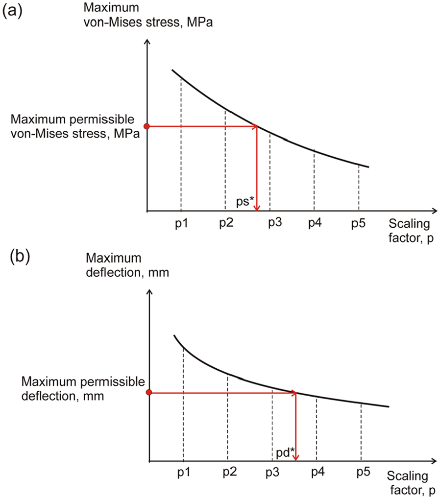
(a) The dependence maximum von-Mises stress – scaling factor and (b) the dependence maximum deflection – scaling factor.
Next, at the same scaling factor values (p1,p2,p3,p4,p5; see Figure 7b), the relationship between the scaling factor and the maximum deflection is obtained (Figure 7b). Using this interpolated graph, the scaling factor pd*, which corresponds to the maximum permissible deflection, is determined for the aggregated element (Figure 7b).
The larger scaling factors p* = max{ps*; pd*} delivers both: a von-Mises stress not exceeding the maximum permissible stress and a maximum deflection not exceeding the maximum permissible deflection. The material saving factor is given as a ratio of the total volume
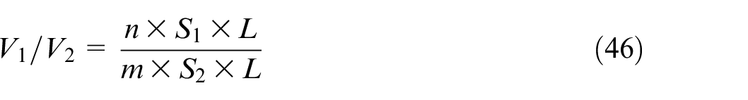
For a scaling factor

Substituting (47) in (46) finally results in
As a result, the proposed interpolation method leads to significant savings of material while maintaining the maximum von Mises stress and deflection below specified safe limits.
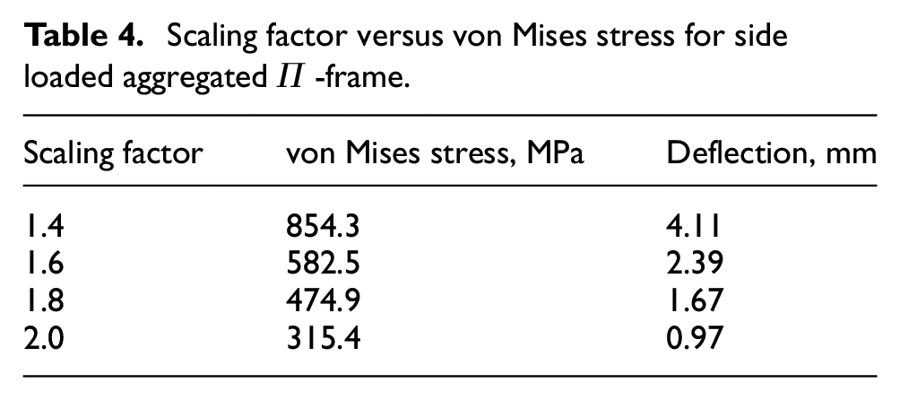
Table 4 and Figures 8 and 9 give the dependencies scaling factor versus maximum von Mises stress and maximum deflection determined from simulations done on Abaqus/CAE 2021 with the side-loaded aggregated frame.
Scaling factor versus von Mises stress for side loaded aggregated
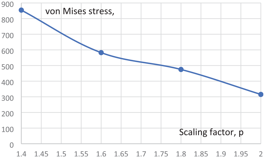
Scaling factor versus von Mises stress [MPa] for side loaded aggregated
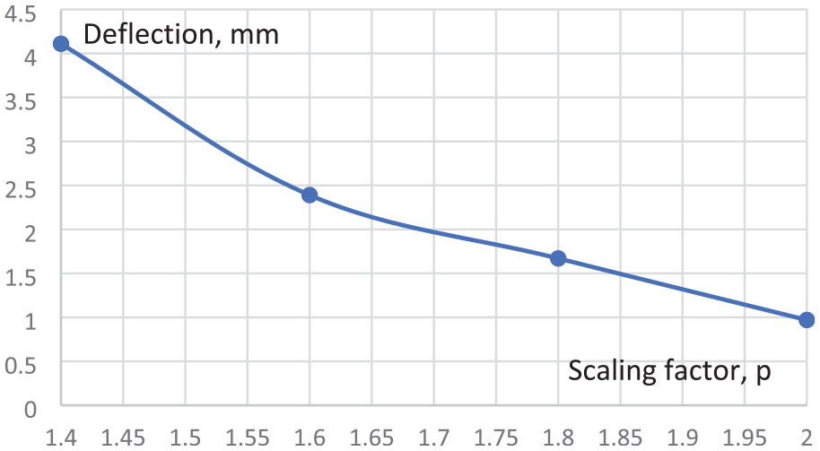
Scaling factor versus von deflection [mm], for side-loaded aggregated
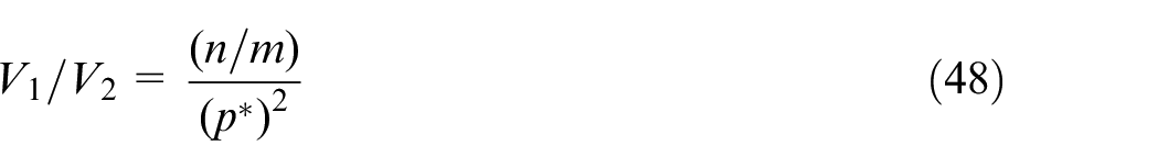
Suppose that the maximum permissible von Mises stress is 605 MPa and the maximum permissible deflection is 3 mm. From the graphs, the scaling factors that deliver maximum permissible stress not exceeding 605 MPa are bigger than 1.58 while the scaling factors that deliver maximum permissible deflections not exceeding 3 mm are bigger than 1.52. The larger scaling factor is p* = 1.58, therefore is the scaling factor that delivers both: a von Mises stress below 605 MPa and deflection below 3 mm. At a scaling factor of p* = 1.58, the calculated by Abaqus maximum von Mises stress is 604 MPa and the maximum deflection is 2.52 mm.
The material savings are calculated from Equation (48):
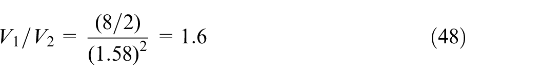
As a result, the total volume of material of the aggregated
Testing the aggregation method on physical prototypes including statically indeterminate
-frames
Testing on centrally loaded
-frames
The aggregation method was tested on physical prototypes including statically indeterminate centrally loaded
Eight-to-two aggregation of centrally loaded
The physical prototype for testing the aggregation method on centrally loaded
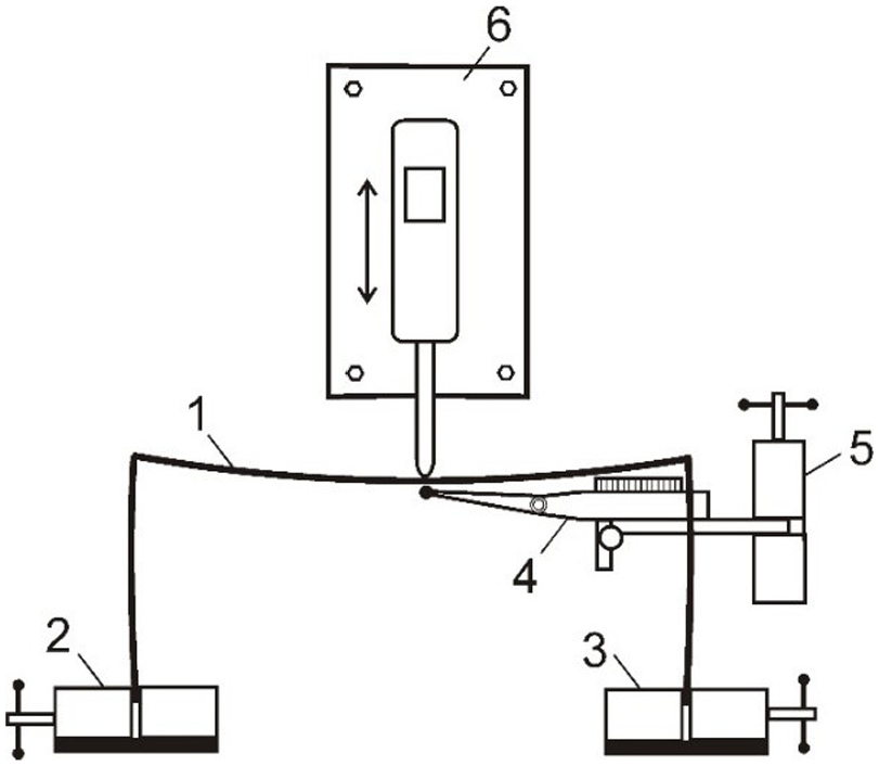
A physical prototype for testing the aggregation method on centrally loaded statically indeterminate
A
Testing the aggregation method on physical prototypes including side-loaded
-frames
The aggregation method was also tested on physical prototypes including statically indeterminate side-loaded frames (Figure 12). The type of aggregation selected for the side-loaded
Eight-to-two aggregation of side-loaded
The physical prototype for testing the aggregation method on side-loaded
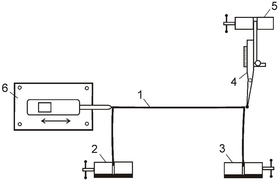
A physical prototype for testing the aggregation method on side-loaded statically indeterminate
A
Experimental results
The results from the experimental study related to the deflections of the
Maximum deflection [mm] for central and side loading of 8 non-aggregated versus 2 aggregated
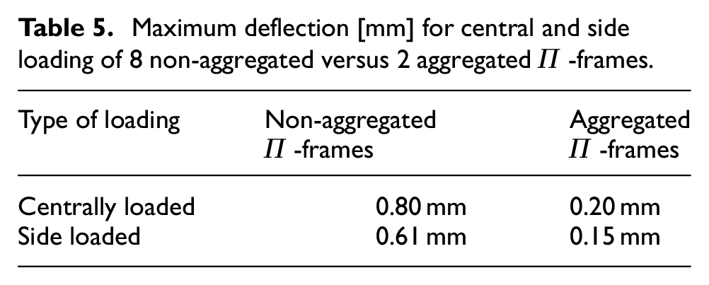
The analysis of the results in Table 5 shows that the aggregated
Conclusions
Aggregating beams with arbitrary cross-sectional shapes into fewer beams with geometrically similar cross sections leads to a dramatic reduction in the volume of material required to support a specified total load. For example, in five-to-one aggregation, the total material volume needed to support the same load is reduced by a factor of 1.71.
For a specified total load, the ratio of the minimum volumes of material required for the non-aggregated and aggregated structures is equal to the scaling factor that relates the dimensions of the geometrically similar cross sections. The ratio of deflections is also equal to this scaling factor. These results hold regardless of the shape of the beam cross sections.
A theorem has been proven that provides the theoretical foundation for the aggregation method in structures containing the same total volume of material. Under this condition, the ratio of the maximum tensile stresses is equal to the scaling factor that relates the dimensions of the geometrically similar cross sections.
For the same total material volume used in both non-aggregated and aggregated structures, the ratio of the maximum deflections is equal to the square of the scaling factor that relates the dimensions of the geometrically similar cross sections. These results are independent of the cross-sectional shape of the loaded beams.
Segmenting multiple loaded beams into a larger number of beams increases the total elastic strain energy of the structure. This result holds true for arbitrary cross-sections of the beams.
Simulation experiments confirmed that aggregating statically indeterminate cantilever beams and statically indeterminate frames leads to a significant increase in the load-carrying capacity of the structures, as measured by both maximum von Mises stress and maximum deflection.
Experiments done on physical prototypes confirmed that aggregating statically indeterminate frames under the same total load results in a significant reduction in maximum deflection.
Beam aggregation also reduces the total surface area along the length of the beams and decreases heat loss due to surface penetration.
An interpolation method has been proposed for reducing the total volume of material while maintain the von-Mises stress and maximum deflection below safe limits.
Footnotes
Declaration of conflicting interests
The author declared no potential conflicts of interest with respect to the research, authorship, and/or publication of this article.
Funding
The author received no financial support for the research, authorship, and/or publication of this article.