
Abstract
Mechanical springs have long been integral to technological systems, yet conventional designs often overlook the potential of natural geometries. Inspired by the golden ratio and the Fibonacci spiral, this study presents a novel resilient biasing device (International Patent No. WO2025/027292A1). The device introduces a fundamentally new spring architecture, offering unique mechanical properties not found in traditional spring forms. This paper investigates its mechanical performance using experimental testing, closed-form analytical modelling, and finite element simulations under both static and dynamic conditions. Results demonstrate that the resilient biasing device provides multidirectional stiffness and effective vibration isolation, with tuneable mechanical characteristics through geometric and material adjustments. New analytical expressions were derived for key parameters, including stiffness, maximum allowable displacement and force, elastic energy, specific elastic energy, and natural frequency. These models enable efficient early-stage design and reducing lead times in product development. Prototypes incorporating the device were developed to validate its broad applicability across comfort-focused products, suspension and actuation systems, energy storage and harvesting devices, impact mitigation solutions, sensors, fasteners, and valve technologies. Overall, the findings reveal that integrating Fibonacci-inspired geometry into spring design can unlock novel performance capabilities, positioning this innovation as a promising advancement in mechanical engineering.
Keywords
Introduction
Elastic energy storage devices have been a focus of research for centuries. The key advantages of the mechanical springs are their capability to absorb vibrations, control motion by an applied force, store elastic energy, and harvest energy.1–4 Other devices for energy storage include: carbon nanotubes, 5 flywheels, 6 stretchable energy storage devices, 7 gravity energy storage device, 8 energy device made of metamaterials, 9 nature inspired structures,10,11 and complex in shape structures made using additive manufacturing technologies.12,13 Mechanical springs have been used for centuries, and they are an integral part of engineering systems. Their wide use in consumer products is evident by the size of the global market. 14 Springs have played a critical role in suspension and actuation systems across industries such as automotive, aerospace, marine, and healthcare. They are fundamental in vehicle suspension systems, including cars, trains, bikes, motorbikes, heavy land vehicles, where they improve ride comfort. 15 They are also used in seats, beds and chairs to support the body and provide comfort. 16 They have been also employed in energy harvesting systems and sensors, where springs made of piezoelectric materials can convert mechanical strain into electrical energy. 17 The ability of springs to store elastic energy allows them to be applied in fluid control systems. 18 Mechanical springs and elastic storage energy devices have the characteristics to isolate vibrations, which is a key advantage in engineering applications.19,20 Variable stiffness control methods in nonlinear dynamic vibration absorbers can enable adaptive vibration suppression by tuning stiffness to dynamic loads, enhancing energy dissipation across broad frequencies.21,22 Mechanical springs are mainly manufactured from high strength metals as one of the requirements of the springs is to endure high cyclic fatigue loads. 23 Composite helical springs have gained considerable attention due to their high strength to weight ratio and corrosion resistant, however, the sustainable manufacturability of helical springs made of composite can be a challenge. 24 Mechanical spring design is governed by several international standards to ensure reliability, safety, and consistency across various industries.25–29
Despite the extensive research landscape in mechanical springs and their well-established presence in engineering, there's a continued need for unexplored shapes that can lead to new mechanical springs with potential advantages in mechanical design, performance, manufacturability, sustainability and/or aesthetics. An example of such a mechanical spring is the resilient biasing device.
30
This resilient biasing device is constructed by two mirrored spirals that are then extruded to form a 3D geometry that has the capability to elastically deform under loading and release the elastic energy after the load is removed. The principal inspiration that led to this invention was drawn from the golden ratio and its occurrence in nature. The golden ratio, approximately equal to ϕ = 1.618, is a universal constant prevalent in nature, dating back to its use in mathematics by ancient Greeks. Euclid, around 300 BC, employed a rectangular shape with sides ϕ and ϕ−1 (0.618), discovering its diagonal to be
Building on the functionality of the resilient biasing device (WO2025/027292A1) to store and release elastic energy, this paper aims to generate new knowledge on its mechanical characterisation by researching the impact of geometry and material performance on the static and dynamic performances. The innovation of the resilient biasing device lies in its unique design based on mirrored Fibonacci spirals providing multi-directional stiffness and vibration isolation capability. To enable rapid product design and development, novel closed-form analytical solutions were developed in this paper. The paper first describes the geometrical principles of the resilient biasing device followed by providing characterisation of the device in its static and dynamic performance. The geometrical principles include the investigation of the overlay dimensions and thickness of the device constructed by a mirrored Fibonacci spiral as well as investigation of other spiral types (Archimedean, Golden, Hyperbolic, Involute and Limacon). The static analyses include the investigation of stiffness, maximum allowable displacement, maximum allowable force and elastic energy. The dynamic analyses include the natural frequency of the device itself as well as its dynamics performance to isolate vibrations as part of a system. The methods used in this study include analytical formulations, finite element models and experimental tests. The experimental tests are used to validate finite element models, which are employed to understand the impact of geometrical parameters and material properties on the static and dynamics performance. The data generated from the finite element analyses is used to obtain constants for the analytical formulations. The paper includes a comprehensive discussion, supported by prototypes, to illustrate the broad applicability of the resilient biasing device.
Research methods
Design concept of the resilient biasing device
The key innovation of the resilient biasing device is mirroring and connection of two spirals to form a geometrical shape that can act as a mechanical spring. 30 The concept of the resilient biasing device was demonstrated using a mirrored Fibonacci spiral as shown in Figure 1. First a single two-dimensional spiral was constructed based on the Fibonacci sequence: 1, 1, 2, 3, 5, 8, 13, 21, and 34 with measurements in millimetres. The spiral was formed by arcs with radii of 1, 1, 2, 3, 5, 8, 13, 21, and 34 mm. The single Fibonacci spiral was then mirrored to form two connection points between the arcs with radii of 34 mm and 13 mm. The active part of the resilient device to store elastic energy is defined by three arcs with radii of 34 mm, 21 mm and 13 mm. The remaining arcs are not used for storage of elastic energy, buy they find applicability in attaching the resilient biasing device to other mechanical systems. This mirrored two-dimensional wire-based spiral was extruded to generate a three-dimensional surface. To form a solid part, a thickness is defined to the surface in the inward direction. An example of a three-dimensional resilient biasing device attached to a bracket is shown in Figure 2. The key geometrical parameters are height (h), length (L), extrusion width (w), and thickness (t). For the mirrored Fibonacci spiral, the ratio of L/h is approximately 1.236 (68/55). The overall dimensions to obtain a large or small size can be achieved by scaling up or down the three-dimensional surface while keeping the L/h ratio unchanged to maintain the Fibonacci spiral. However, there are no limitations on applying the scaling in only one direction, where the L/h ratio can change, resulting in different mechanical performance. The types of spirals that can be used to form the resilient biasing device are unlimited, providing the opportunity to investigate six spirals in this study. The six spirals are modelled in ANSYS SpaceClaim by specifying their representative equations. The height of 68 mm was kept the same for all six spirals, as well as the extrusion width of 20 mm, and thickness of 1mm. Figure 3 shows a front view of the three-dimensional surfaces defined by mirrored Fibonacci, Archimedean, Golden (a type of logarithmic spiral), Hyperbolic, Involute, and Limacon spirals. The lengths differ for the spirals, with the Fibonacci and Golden spirals having similar lengths. The two connecting points for the mirrored Fibonacci spirals were at the same location, but for some other mirrored spirals, the upper (top) connection point resulted in a sharp contour, which could act as a stress concentration factor, increasing the stress levels and hence reducing the capacity of the resilient biasing device to carry load under elasticity. Geometrical modifications were made to the Archimedean spiral, where the two upper points were connected with a straight line, while the Golden and Hyperbolic spirals were rounded with an arc at the top to create smooth transitions between the two merged spirals at the top of the resilient biasing device.
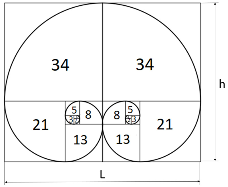
Mirrored Fibonacci spiral utilised in the formation of a resilient biasing device. 30
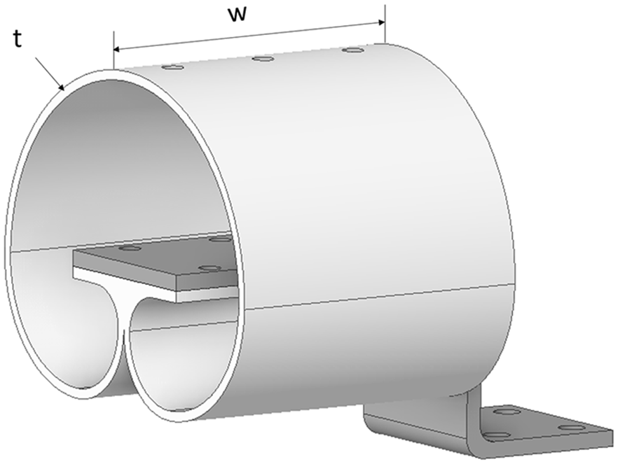
An example of a three-dimensional resilient biasing device mounted on a bracket. 30
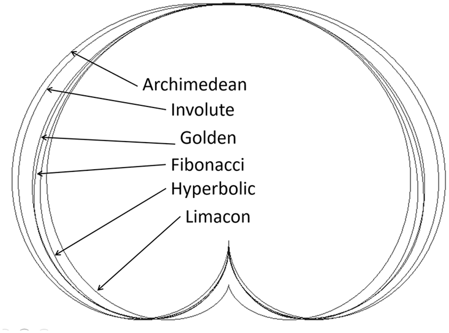
An illustration of mirrored spirals (Archimedean, Involute, Golden, Fibonacci, Hyperbolic, and Limacon spirals).
Experimental tests
The experimental work is divided into two strands. The first strand involves conducting experimental compression, tensile and bending quasi-static tests on a resilient biasing device made of Ti6Al4V. The second strand focuses on performing dynamic vibration analyses and investigating the vibration transmissibility of the resilient biasing device made of PLA. The rationale for selecting Ti6Al4V lies in its high elastic limit, which is comparable to that of high-strength steel, combined with a relatively low Young’s modulus, approximately half that of steel. This unique combination allows Ti6Al4V to store a greater amount of elastic energy, making it an excellent candidate for mechanical spring applications. For the dynamic analysis, PLA polymer is used due to its higher material damping ratio compared to metals. This characteristic helps to attenuate resonance peaks, thereby minimising the risk of excessive vibrations and reducing potential health and safety concerns when resonance frequencies are encountered.
Quasi-static testing
Compression, tensile and bending tests were conducted on the same resilient biasing device, which was additively manufactured. Laser powder bed fusion technology was utilised on the TruPrint1000 (Trumpf) with a 30µm layer thickness. Solid support structures connected the part to the baseplate, which were subsequently removed by wire electric discharge machining after stress relief. Three fixtures were designed and fabricated to enable compression, tension and bending tests on the 50 kN Shimadzu machine. The same displacement rate of 1 mm/min was applied to the three tests. For each loading condition, three repeatable tests were performed before the data was acquired. Figure 4 shows the additively manufactured Ti6Al4V as well as the resilient biasing device subject under compression, tension and bending testing. A feature for the compression and tensile testing is the square slot just above the connecting point of the two Fibonacci spirals. The load is applied at the top of the resilient biasing device by moving the platform down for compression or up for tension. The force is then reacted at the pin which connects the resilient biasing device with the corresponding fixture, and the force-displacement relationship was measured with accuracy of ±0.5% as per machine specification.
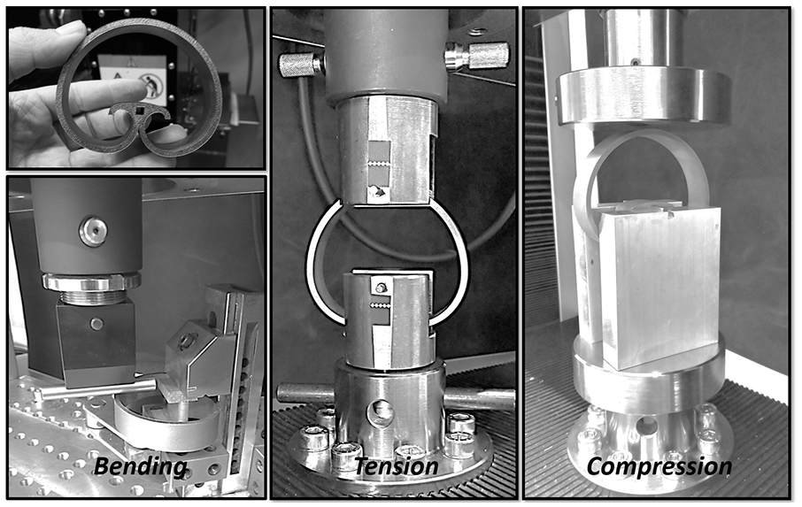
An experimental setup for a quasi-static testing in tension, compression and bending.
Vibration testing
The vibration testing was conducted on the commercial electrodynamic LDS V780 vibration testing system manufactured by Brüel & Kjær, as shown in Figure 5. An aluminium plate was mounted on the shaker, with a control accelerometer (Brüel & Kjær 4533-B, sensitivity of 9.81 mV/g) attached at the centre of the plate. The primary function of the control accelerometer is to feed a signal to the shaker’s control system. An aluminium structure was fabricated and assembled to represent overall dimensions and mass of a prototype baby incubator. This structure was mounted on four resilient biasing devices, as depicted in Figure 5. The resilient biasing device and the aluminium structure were connected with three bolts. The four resilient biasing devices were designed based on the concept in Figure 2, with the difference that the bracket was represented by a solid plate attached to the resilient biasing device with six bolts. The mass of the aluminium structure, side boards, mattress, and a manikin was approximately 42 kg. The four resilient biasing devices were designed with a thickness of 3.8 mm, a height of 125 mm, and an extrusion width of 120 mm. The resilient biasing devices were 3D printed on the Ultimaker 2+ machine using PLA filament. The printing specifications included a nozzle size of 0.8 mm and a layer thickness of 0.2 mm.
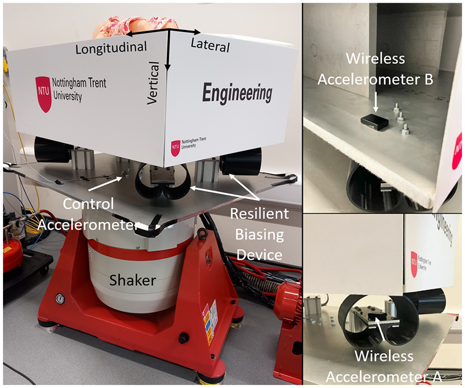
Experimental setup of a vibration system to analyse the vibration isolation capability of the resilient biasing device.
To excite the system, harmonic sinusoidal vibrations were applied in the vertical direction at an acceleration amplitude of 0.1 g (0.981 m/s2) and frequencies ranging from 2 to 80 Hz. The acceleration levels were monitored and controlled by the control accelerometer. Two Axivity AX3 wireless accelerometers (Accelerometer A and Accelerometer B) with a sampling rate of 3200 Hz were attached to the system, as shown in Figure 5. Accelerometer A was attached to the centre of the resilient biasing device to measure the incoming vibrations from the shaker and the aluminium plate. Accelerometer B was attached to the aluminium structure just above the top of the resilient biasing device. The vibration transmissibility was obtained as the ratio of the acceleration amplitude from Accelerometer B to the acceleration amplitude from Accelerometer A.
Finite element analysis models
Static and Modal Models
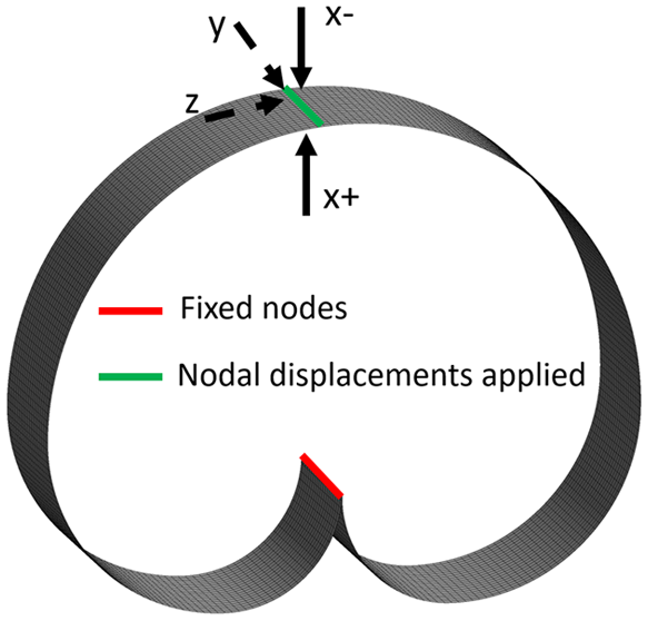
To replicate the quasi-static compression, tension and bending tests from Figure 4, as well as to investigate the effects of geometrical parameters on mechanical performance, a shell-based model was developed in ANSYS Mechanical based on a three-dimensional extruded surface. Figure 6 illustrates an exemplar of a shell-based FEA model of the resilient biasing device, meshed with 1 mm quadratic 8-node shell elements. A uniform mesh size was applied across all investigated geometries, following a mesh sensitivity analysis. The analysis showed that reducing the element size to 0.5 mm resulted in changes of less than 0.5% in the predicted stresses and displacements, confirming mesh independence. The thickness of the shell elements was defined to meet the geometric requirements. Zero displacements were applied to the lower connection line (red line) in all three directions (x, y, z). At the top connection line of the resilient biasing device (green line), displacements were applied to represent compression (x−), tension (x+), and transverse loading (y and z). For the bending scenario, a displacement was applied at a single point on the edge of the green line. These displacements were applied separately in each direction to investigate the mechanical response. Ti6Al4V material properties (Young’s modulus E = 107 GPa, Poisson ratio = 0.3, density of 4430 kg/m3) were utilised in both static and modal analyses. For all static analyses, which were used to explore the static mechanical performance of the resilient biasing device, displacements were applied at the top centre of the device (green line), and the reaction forces were predicted at the fixed nodes with zero displacements in all directions (red line). The analyses incorporated formulations for large deformations enabling to model the geometric nonlinear effects. Modal analyses were conducted to predict the natural frequencies of the device. In the modal analyses, only the zero displacement boundary conditions were applied in all directions, with no loads or additional displacements applied.
An example of FEA model of the resilient biasing device for static and modal analyses.
Random vibration model
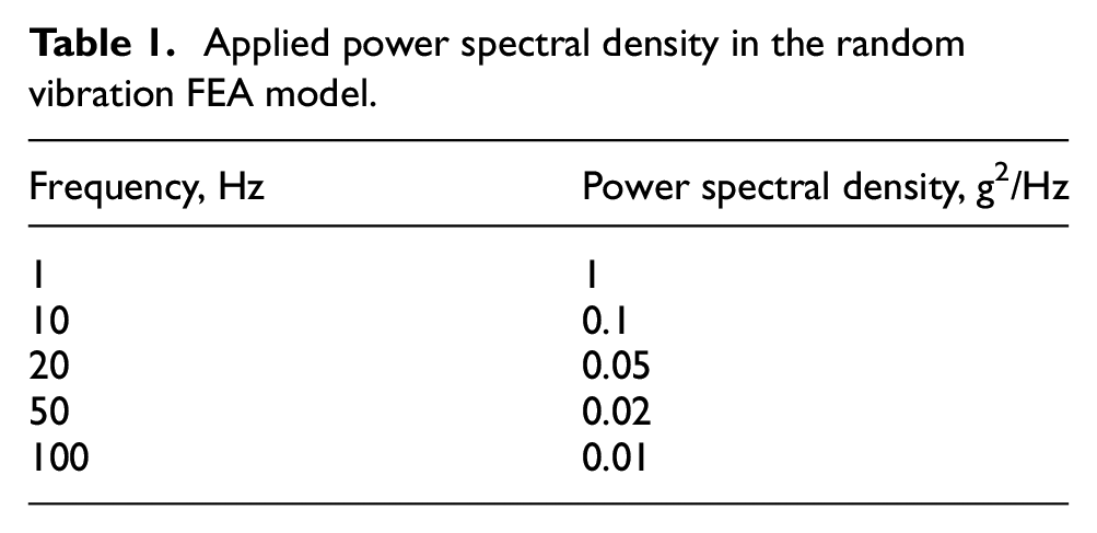
An FEA model was developed in ANSYS (see Figure 7) to represent the experimental system from Figure 5. The resilient biasing devices were modelled with shell elements, specifying a thickness of 3.8 mm to represent the experimental system. The mass of the prototype baby incubator was represented as a point mass attached to the resilient biasing devices using rigid beam elements, which connected the point mass with the finite element nodes at the top of the device (green lines). It is important to note that each of the resilient biasing devices was attached to the prototype baby incubator with three bolts. The assumption was made that all top nodes were connected with the surface of the incubator, based on the assumption that gravity load ensures contact at that interface. The centre of the mass was calculated and applied in the model. Young’s modulus of 3.8 GPa, Poisson ratio of 0.41, and density of 1250 kg/m3 were used for the PLA material. To represent the connection between the resilient biasing device and the plate attached to the shaker, zero displacements in all directions were applied to the connection edges of the modelled resilient biasing devices (red lines). First, a static analysis was performed under a gravitational load of 9.81 m/s2. The predicted stresses were then used as input for a modal analysis, where the natural frequencies and mode shapes in the range of 0–100 Hz were predicted. These predicted mode shapes and natural frequencies were subsequently used in a random vibration analysis. A power spectral density for frequencies in the range of 1–100 Hz was applied at the fixed nodes with zero displacements (see Table 1). A damping ratio of 0.04 was applied to consider the damping of the resilient biasing devices and the bolted joints. The predicted power spectrum density at the top of the resilient biasing devices was used to determine the vibration transmissibility.
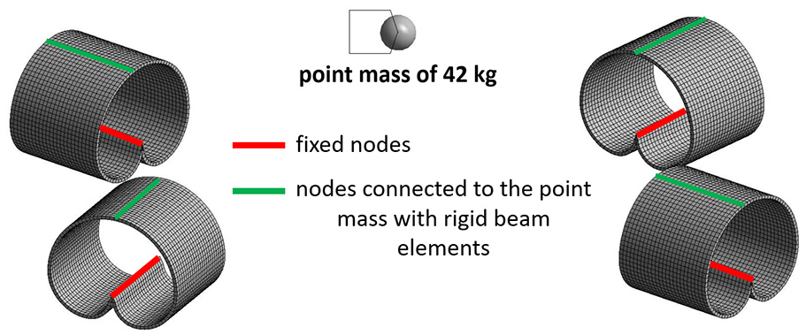
FEA model of the experimental setup for vibration testing.
Applied power spectral density in the random vibration FEA model.
Analytical closed-form solutions under compression
Afazov et al. 30 derived for the first time an analytical expression for the resilient biasing device constructed with mirrored Fibonacci spiral to predict stiffness (k) in compression, considering the device’s height (h), thickness (t), extrusion width (w), and the material's Young’s modulus (E), represented as:
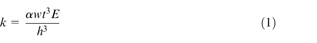
where
For the same mirrored Fibonacci spirals, Afazov et al. 30 derived the relationship between the maximum displacement (δmax), height, thickness, stress limit (σlim), and Young’s modulus by:
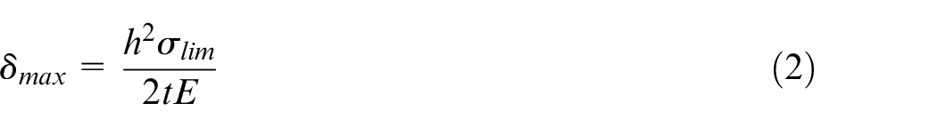
Equation (2) has a close analogue with the maximum displacement for leaf springs, where the length of the leaf spring is squared, while the thickness, stress limit, and Young’s modulus have linear expressions. 27 The width of the leaf spring does not contribute to the maximum displacement, which is also true for the resilient biasing device. The stress limit in equation (2) can represent the elastic limit or yield stress of the material, as well as the fatigue limit or creep limit, depending on the application’s performance requirements. Therefore, the stress limit is determined based on the application and the load characteristics. In this context, the elastic limit, represented by the yield stress of the material, was used as the stress limit to determine the maximum displacement within the device’s elasticity.
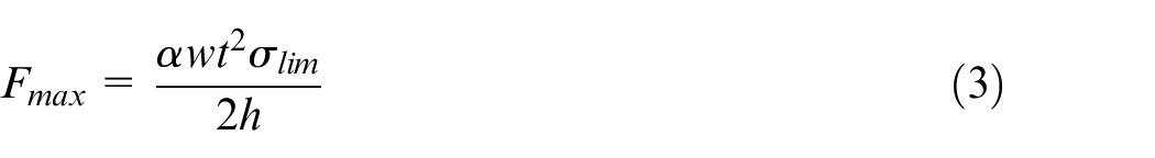
At the design stage of many engineering applications, it is also necessary to determine the maximum load that the device can withstand. By applying the Hooke’s law,
From a design perspective, the stress limit should be considered first, depending on the material and its manufacturing specifics. For engineering designs, the resilient biasing device must meet requirements for stiffness, loads, durability, and displacement. Another beneficial mechanical performance parameter in the design stage is the maximum amount of elastic energy (
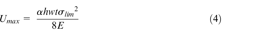
Equation (4) demonstrates that the geometric parameters (height, thickness, and width) have a linear impact on the elastic energy stored within the resilient biasing device. The stress limit has the most significant influence on the elastic energy. If the stress limit is represented by the elastic limit of the material, the maximum elastic energy that can be stored is reached. Equation (4) indicates that materials with a high elastic limit or yield stress and a low modulus of elasticity can enhance the device's capacity to store elastic energy. This suggests that devices designed with higher stress limits and lower material stiffness can store greater amount of elastic energy, exemplified by the potential of Ti6Al4V in metal applications.
Another important property of the device is its mass. The mass of the device is important for lightweight solutions. The mass (m) of the mirrored Fibonacci spirals with three arcs can be given by:
where
Another mechanical property that can be key for design applications is the natural frequency of the resilient biasing device under compression load. The natural frequency for a compression spring can be given by
Results and analyses
Comparison of experimental and FEA force-displacement results
Mechanical tests under compression, tension and bending were conducted to establish the force-displacement relationship of the additively manufactured Ti6Al4V resilient biasing device. The force-displacement relationship was also predicted using the developed FEA model (see Figure 6). For the bending setup, the nodes representing the clamped surfaces were fixed in all direction in the FEA model. Figure 8 compares the experimental and FEA predicted force versus displacement behaviour under tension, compression, and bending. In the experiments, the resilient biasing device was first loaded with 2500 N, followed by unloading for both tension and compression. For the bending experiment, a maximum displacement of 7.4 mm was applied because this was the limit for the developed fixture. No permanent deformations were indicated, as the unloading curves followed the loading curves for all the three loading conditions. This was the case for all conducted experiments. The experimentally obtained and FEA predicted stiffness values, after fitting a linear equation to the data points under compression, were 415.5
Comparison of experimental and FEA predicted force-displacement behaviour under tension, compression and bending, featuring an extrusion width (w) of 20 mm, height (h) of 68 mm and thickness (t) of 3 mm.
Mechanical performance under compression
The relationship between geometrical parameters and mechanical performance was established using the analytical closed-form solutions and FEA models for the resilient biasing device constructed with the Fibonacci spiral. Figure 9 showcases analytical and FEA results for stiffness prediction with varying thicknesses and heights. Non-linear effects on stiffness were observed for height and thickness, both exhibiting cubic relationships as it can be seen in equation (1). Understanding that stiffness is pivotal for mechanical spring designs, the maximum allowable displacement under specified stress limits is also a key characteristic for a spring. In this study, a stress limit of 970 MPa, representing the elastic limit of the additively manufactured Ti6Al4V alloy, was used to obtain the maximum allowable displacement that a spring can withstand without permanent/plastic deformations. Figure 10 shows that thickness and height exhibited non-linear effects on the maximum allowable displacement, while the extrusion width was found to have no influence. In applications where fatigue and/or creep need to be considered, the stress limit should be set to lower values depending on the material's performance under fatigue and/or creep. Determining stiffness and maximum allowable displacement allows for the computation of the maximum allowable force and capacity to store elastic energy, which can be key performance indicators for design requirements. Another physical property of the resilient biasing device is its natural frequency. Figure 11 shows the natural frequency under the compression mode. It can be analysed that thickness has a linear behaviour, while the gradient of the plots shows a non-linear decrease with increasing height, indicating that height has a non-linear effect on the natural frequency, as seen from equation (6). A harmonious correlation between analytical solutions and FEA predicted results was demonstrated, displaying an average percentage difference of 2.54%, 6.95%, and 2.27% for maximum allowable displacement, compression stiffness, and natural frequency, respectively. This indicates that the developed analytical equations can be employed in the design of resilient biasing devices to determine geometrical parameters and materials, considering design space limitations as well as performance and application requirements.
Comparative analysis results between analytical closed-form solutions and FEA predicted compressive stiffness, featuring an extrusion width (w) of 20 mm.
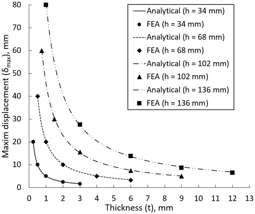
Comparative analysis results between analytical closed-form solutions and FEA predicted compressive deformation before the elastic limit is reached, featuring an extrusion width (w) of 20 mm.
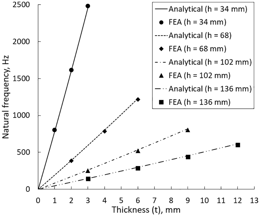
Comparative analysis results between analytical closed-form solutions and FEA predicted natural frequency under compression, featuring an extrusion width (w) of 20 mm.
Mechanical performance in multi-directions
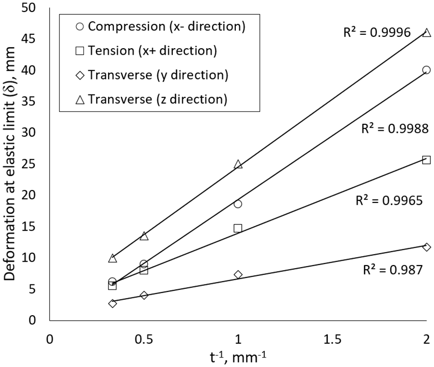
Figures 12–14 present FEA predictions of stiffness under compression (−x), tension (+x), and the two transverse directions (y and z) for different geometrical parameters. The predicted stiffness in transverse directions reflects a scenario where a rigid object is connected at the top of the resilient biasing device. The relationship between stiffness and thickness, as well as stiffness and height, adheres to a power law. For stiffness under tension, compression, and the transverse z direction, the power law is cubic. Linear relationships between stiffness and width are observed in tension, compression, and the transverse z direction. This indicates that the closed-form analytical solutions developed under compression could be applied under tension and transverse z direction loading. The linear dependence on width and the cubic dependence on thickness can be attributed to the moment of inertia. However, in the transverse y direction, the relationship displays non-linear characteristics for the extrusion width. Additionally, the height showed a power law with an exponent of 3.5. This can again be attributed to the moment of inertia, where the width has a more pronounced influence on the moment of inertia in the y direction. Analysing the deformation behaviours, Figures 15–17 depict predicted deformations upon reaching the elastic limit. The FEA predicted displacements in compression, tension, and the transverse z direction obey the developed closed-form formulation, with height having a quadratic effect and thickness a parabolic effect. However, in the transverse y direction, the increase in extrusion width showcases a non-linear decrease in displacement with an exponent of −0.574, while height shows a greater influence with an exponent of 2.44. The takeaway from these analyses is that the presented closed-form analytical solutions need to be modified to capture the behaviour in the transverse y direction too.
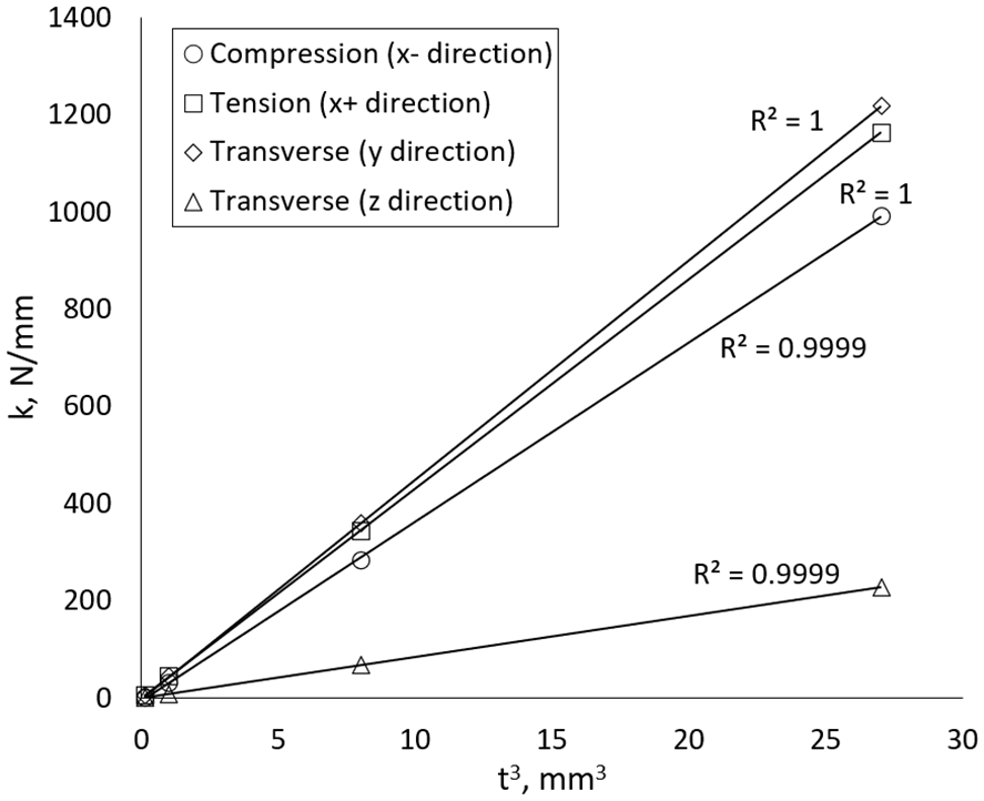
FEA predicted stiffness versus thickness with power exponent of 3 at w = 40 mm and h = 68 mm. R indicates the error after fitting a linear equation.
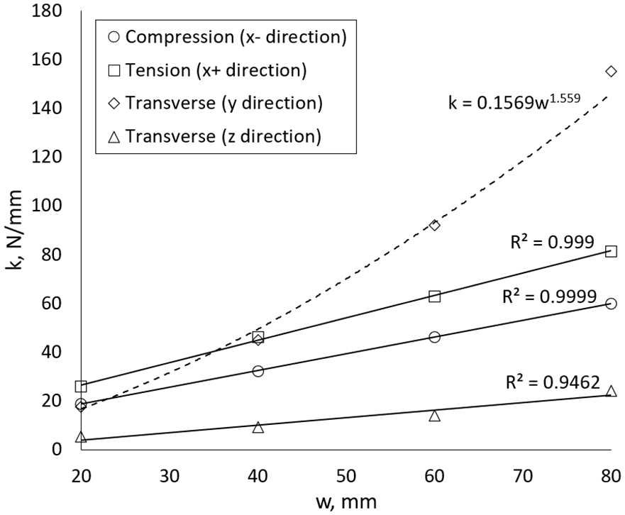
FEA predicted stiffness versus extrusion width at h = 68 mm and t = 1 mm. R indicates the error after fitting a linear equation with exception to the transverse y direction where a power equation is fitted.
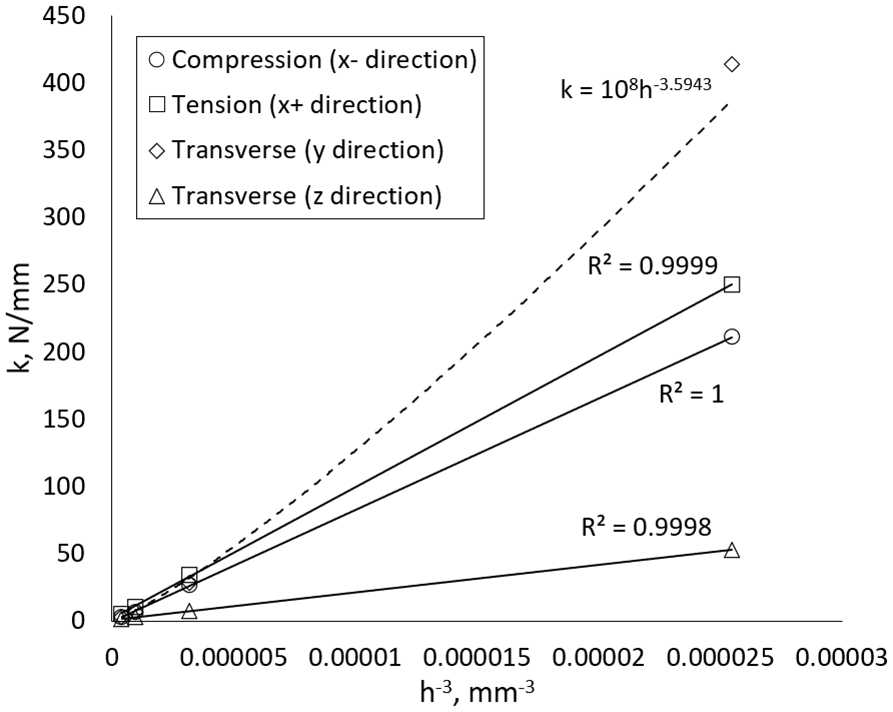
FEA predicted stiffness versus height with power exponent of −3 at w = 40 mm and t = 1 mm. R indicates the error after fitting a linear equation with exception to the transverse y direction where a power equation is fitted.
FEA predicted deformation at the elastic limit of 970 MPa versus thickness with power exponent of −3 at w = 40 mm and h = 68 mm. R indicates the error after fitting a linear equation.
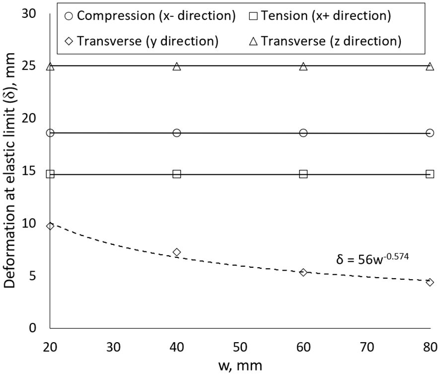
FEA predicted deformation at the elastic limit of 970 MPa versus extrusion width at h = 68 mm and t = 1 mm. A power equation is fitted for the transverse y direction.
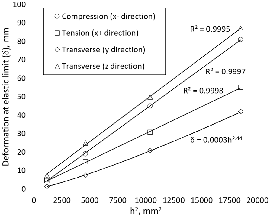
FEA predicted deformation at the elastic limit of 970 MPa versus height with power exponent of −2 at w = 40 mm and t = 1 mm. R indicates the error after fitting a linear equation with exception to the transverse y direction where a power equation is fitted.
Generalised analytical closed-form solutions
The results from section ‘Mechanical performance in multi-directions’ indicate that the transverse y direction exhibited different non-linearities for the width and height of the mirrored Fibonacci spirals. Consequently, to enhance the applicability of the proposed equations in section ‘ Analytical closed-form solutions under compression’ in multiple directions, the following generalised equations are suggested for stiffness and displacement.


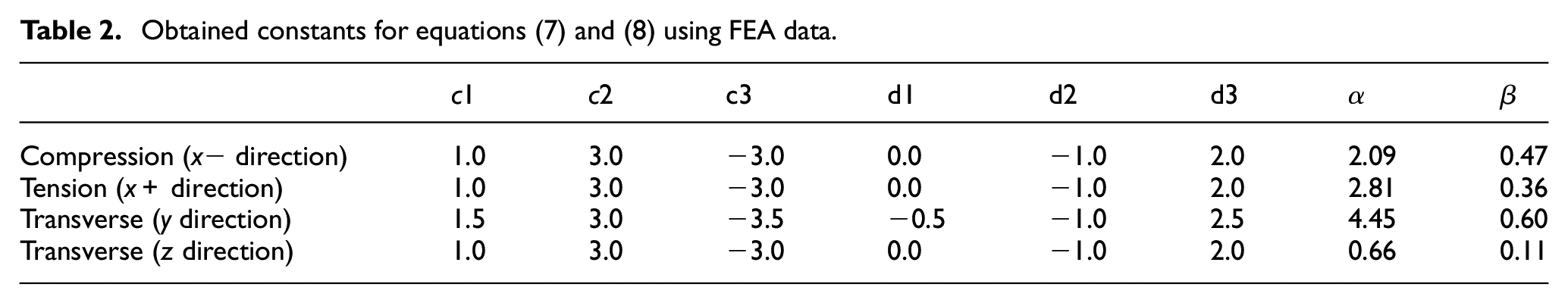
To maintain the unit of Nm−1 for stiffness, assuming w, t, and h are in mm, the sum of the constants c1, c2, and c3 should be equal to one (c1 +c2 +c3 = 1). For example, in equation (1), c1 = 1, c2 = 3, and c3 = −3. This results in (mm1 × mm3 × mm−3 × Nmm−2 = Nm−1) and constant α is unitless. The same principle applies to equation (2), where to keep the unit in mm, the sum of constants d1, d2 and d3 should be equal to one (d1 + d2 + d3 = 1). For example, in equation (2), d1 = 0, d2 = −1 and d3 = 2. Based on these principles and the results from section ‘Mechanical performance in multi-directions’, Table 2 shows the proposed constants c1, c2, c3, d1, d2 and d3 for compression, tension, and the two transverse directions. To obtain constants α and β, further FEA results were obtained to generate more data points. Figure 18 shows plots for FEA predicted stiffness in all four directions versus equation (7) using constants c1, c2, and c3 for each direction from Table 2. The gradient (unitless) represents the constant α for each direction. Applying the same principles but for displacement, constant β is also obtained for each loading, as shown in Figure 19. Constant α can be used to understand the stiffness factor in each direction, while constant β is an indicator for the displacement factor. For instance, the resilient biasing device constructed with mirrored Fibonacci spirals is 3.17 times more flexible in the transverse z direction than under compression (2.09/0.66 = 3. 17). Compared to the experimental results presented in Section ‘Comparison of experimental and FEA force-displacement results’, the analytically calculated stiffness under compression is 384 N/mm—7.5% lower than the experimental value and 4.9% lower than the FEA prediction. Under tension, the calculated stiffness is 516.4 N/mm, which is 13.5% higher than the experimental result and 11.7% higher than the FEA prediction. These findings suggest that the proposed generalised analytical solutions can serve as a useful preliminary design tool, providing initial estimates that should be further validated through finite element analysis and experimental testing as part of a product development process.
Obtained constants for equations (7) and (8) using FEA data.
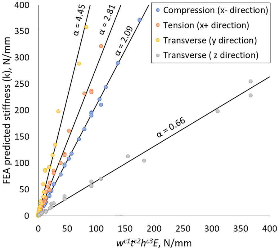
FEA predicted stiffness with obtained constant α in all directions.
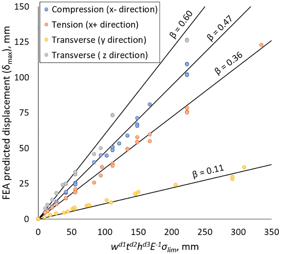
FEA predicted displacement at the elastic limit of 970 MPa with obtained constant β in all directions.
Force-displacement analysis of various spiral designs
In addition to height, extrusion width, and thickness, the resilient basing device can be constructed with various spirals. The six mirrored spirals in Figure 3 were analysed using FEA under compression. Geometrically, the L/h ratio varies among the different spirals. The Archimedean spiral has the greatest length, resulting in an L/h of 1.375, compared to 1.236 for the Fibonacci spiral. Figure 20 illustrates the force-displacement under compression, as well as the calculated stiffness and specific energy for each spiral. The elastic limit is determined based on the threshold of 970 MPa. The Fibonacci and golden spirals exhibit comparable force-displacement performance due to their similar geometries. The Archimedean spiral demonstrates the lowest stiffness, while the Limacon exhibits the highest. Comparing specific elastic energy, the Fibonacci, Golden, Involute, and Archimedean spirals have higher values, indicating they can store more elastic energy per unit mass. Further FEA data were obtained for the Fibonacci spiral by scaling the resilient biasing device in the z direction only, allowing for length enlargement while maintaining the same height and width. By applying this scaling to increase the length and keeping the L/h ratio at 1.375, similar to the Archimedean spiral, the stiffness reduced from 13.1 N/mm to 9.9 N/mm, comparable to the Archimedean spiral’s 9.7 N/mm. The specific energy increased from 104 J/kg to 110 J/kg. These analyses indicate that the choice of spiral can be also used for controlling stiffness and allowable deformations. The Fibonacci spiral appears to be a favourable option among the six spirals due to its high specific elastic energy. Its length can be modified by scaling in one direction, which can decrease stiffness and increase allowable displacement if the L/h ratio is increased, and vice versa. In comparison to the effects of height and thickness on stiffness, the type of spiral can also be utilised to meet design and performance requirements. The impact of spiral types is expected to significantly influence stiffness in the transverse directions, providing an additional design variable for achieving balanced multi-directional stiffness suited to diverse engineering applications. Additionally, incorporating variable thickness offers another geometric feature to fine-tune stiffness characteristics in multi-directions.
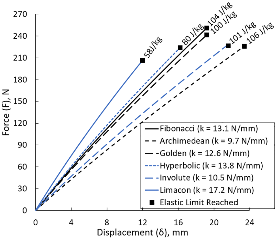
Comparison of FEA predicted force-displacement behaviour under compression for six spirals at h = 68 mm, w = 20 mm, and t = 1mm.
Vibration isolation performance
The random vibration FEA model predicted the power spectral density, which was used to obtain the vibration transmissibility for the frequency range of 1–100 Hz. Figure 21 illustrates the experimentally obtained and FEA predicted vibration transmissibility in the vertical direction. The resonance under compression occurs at 8.08 Hz, with vibration transmissibility just above a value of 10. The experimentally obtained values align with the FEA predictions across the analysed frequency spectrum, validating the FEA model. The damping ratio of 0.04 applied in the FEA matches the transmissibility magnitude at the resonance peak of 8.08 Hz. It should be noted that damping can be influenced by how the resilient band device is attached to the prototype baby incubator. Frequencies exceeding 12 Hz demonstrate the vibration isolation capability of the resilient biasing device, indicating that it can isolate vibration once the system's excitation frequency is approximately 1.5 times greater than its natural frequency. Additionally, transmissibility can drop below 0.1, which is equivalent to more than 90% vibration isolation. The key takeaway from the experimental and FEA predicted results is that resilient biasing devices can effectively isolate vibrations in mechanical systems.
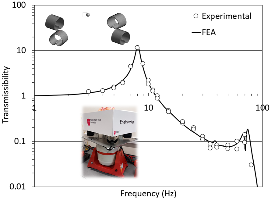
Comparison of experimental and FEA predicted vibration transmissibility under compression (vertical direction).
Geometrical parameters are crucial in determining the natural frequencies at different mode shapes, which dictate dynamic performance. Sufficient damping is also essential to reduce peaks at resonance frequencies. The damping ratio of 0.04 was found to best describe the experimental transmissibility. The damping contribution is due to the 3D printed PLA material, reported to range from 0.01 to 0.02. 41 The additional damping arises from the bolted joint between the resilient biasing device and the prototype baby incubator due to friction. Resilient biasing devices made with rubber can further increase system damping, while those made of metals would reduce it. Figure 22 shows how increasing the damping ratio reduces transmissibility at the resonance frequency under compression payload. Conversely, reducing damping, such as with metal devices welded to the frame, can result in low damping. Low damping can increase transmissibility in other resonance frequencies, affecting vibration isolation performance. For instance, at a frequency of 74.4 Hz, transmissibility is close to 1 for a damping ratio of 0.01. Therefore, it is desirable to increase the damping ratio in any design system. This could be achieved through careful selection of damping materials (e.g. viscoelastic polymers and elastomers) or design elements (e.g. embedded dampers) integrated within the resilient biasing device.
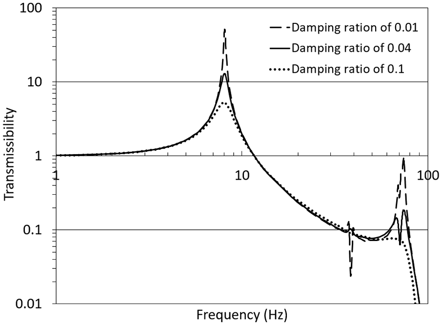
Effects of damping ratio on the vibration transmissibility under compression (vertical direction).
Figure 23 illustrates the vibration transmissibility in the vertical, transverse, and longitudinal directions. It can be observed that the natural frequency in the transverse and longitudinal directions is approximately 3.8 Hz, which is lower than that in the vertical direction (8.08 Hz). This difference is attributed to the lower stiffness in the transverse and longitudinal axes. Vibration isolation commences at approximately 5.4 Hz in the transverse and longitudinal directions, and the transmissibility remains below unity for frequencies up to 100 Hz using the same damping ratio of 0.04. This analysis demonstrates that vibrations can be effectively isolated in multiple directions using the resilient biasing device. For example, in the current design, a transmissibility of less than 0.12 is achievable in all three directions at 30 Hz. Furthermore, vibration transmissibility can be utilised in stress and fatigue analysis during mechanical design to optimise both dynamic and durability performance. For instance, under a static load of 1 g (9.81 m/s2) in the vertical direction, the maximum principal stress predicted for this configuration is 14.4 MPa, which can be used for further fatigue and creep analyses needed in product design. The calculated stress is more than two times lower than the yield strength of PLA (approximately 30 MPa), indicating that the material will remain within the elastic range and no permanent deformation is expected.
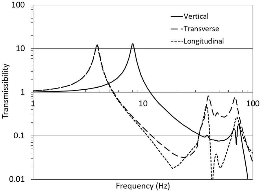
FEA predicted vibration transmissibility in the vertical, transverse and longitudinal directions.
Discussion and applications
Multiple loop design concept
The design space within the resilient biasing device allows for the construction of devices with multiple spirals, which can be assembled. For example, Figure 24 illustrates double-loop resilient biasing devices connected by an elastic cord to form a unit. This double-loop design distributes stress across two loops instead of one, enabling larger loads to achieve the same allowable displacement before reaching the specified stress limit. In this example, the inner resilient biasing device is scaled in height, length, and thickness by a factor of 0.75, while the extrusion width remains unchanged. According to equation (1), the ratio between thickness and height is cubed, ensuring the load is evenly distributed between the two loops after scaling. This increases stiffness while maintaining the same maximum allowable displacement at the specified stress limit. Another consideration for the unit arrangement is the contact between the resilient biasing devices and an object at the bottom, which affects mechanical performance. Additionally, the connection method (flexible or rigid) can alter the reaction force distribution compared to the configuration investigated in this study, where the devices were rigidly attached at the middle section without bottom contact. Controlling the stiffness of a single resilient biasing device offers applications in comfort-demanding products like seats, sofas, chairs, mattresses, and shoes, as well as vibration isolation needs. Figure 24 also shows that the resilient biasing devices are spaced to allow a gap between them along the length. This gap accommodates deformation under compression, where the device lengthens, and the opposite occurs under tension. This ability to change length could enable the design of functional components such as load-bearing fasteners and fluid control valves. For example, under pressure, the resilient biasing device can close a gap, functioning as a valve. Conversely, under tension, the device's length can be reduced. Once fitted into a gap and the load is released, the stored elastic energy can create a contact force, allowing the resilient biasing device to act as a fastener.
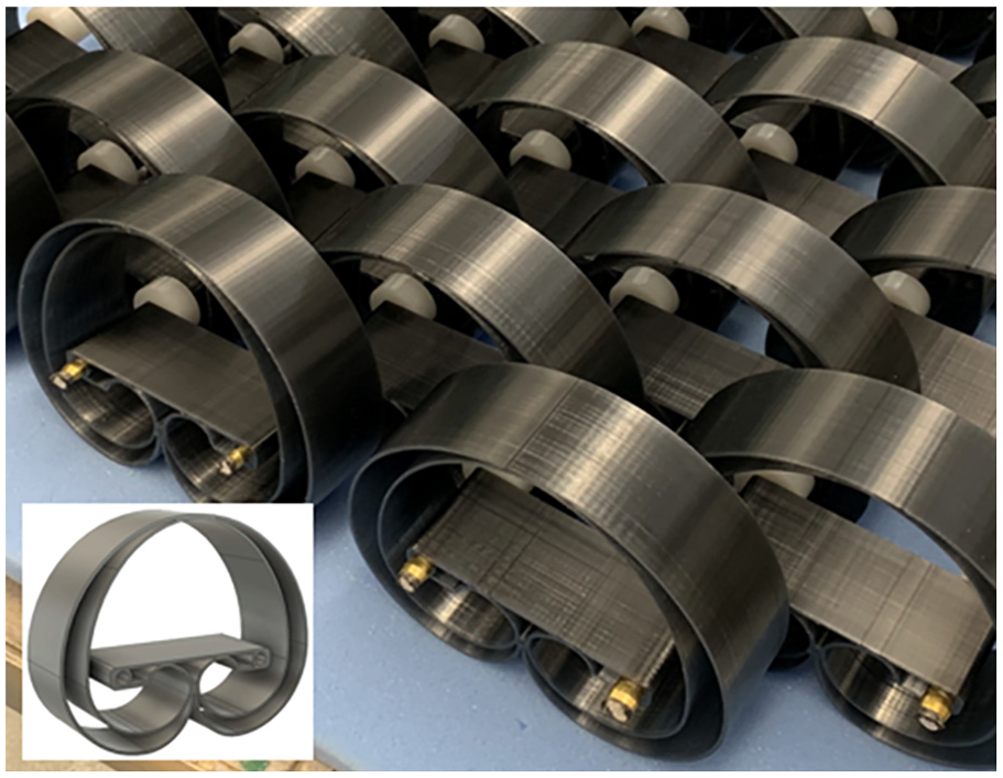
Prototype unit of double-loop resilient biasing devices.
Choice of materials and manufacturing processes
The resilient biasing device is designed with adaptability at its core, allowing for a wide range of material and manufacturing options to suit diverse applications. Its geometry and functionality are compatible with numerous classes of materials, including metals and alloys, polymers, elastomers, ceramics, composites, nano-materials, multi-materials, and even organic and recyclable substances. This wide material palette could enhance the device’s applicability across multiple sectors, from aerospace and automotive to consumer products and medical devices. Material selection is primarily driven by performance requirements, particularly the need to balance high stiffness with large allowable displacements, a fundamental challenge in spring design. This trade-off is governed by the amount of elastic energy the device can store, which is directly influenced by both its geometry and the mechanical properties of the material.
The elastic energy density of a material, defined as 0.5 σ2/E (where σ is the yield stress and E is the Young’s modulus), provides a critical metric for assessing a material’s capacity to store elastic energy. Materials with a high yield strength and relatively low modulus of elasticity are favoured, as they can absorb greater energy for the same volume. For example, Ti6Al4V and high-strength steels may have similar yield strengths (∼1100 MPa), but the lower elastic modulus of Ti6Al4V (107 GPa compared to 207 GPa for steel) allows it to store more elastic energy. Ceramics, despite their brittleness, can show promising elastic energy densities, while certain elastomers and high-performance metals can also perform well. It is worth mentioning that materials with non-linear elastic behaviour could add some design flexibility if non-linear stiffness is required for a given application. Also, non-linearity in stiffness can be contributed due to the change of length at large deformations.
Springs are typically subjected to cyclic and/or sustained loads, necessitating careful consideration of fatigue and creep performance. For high-cycle applications, the design stress is limited by the material’s fatigue limit, whereas in creep-sensitive applications, especially at elevated temperatures, the material’s creep resistance at applied stress becomes critical. In both cases, microstructural stability and the presence of defects introduced during manufacturing can significantly influence performance, underscoring the importance of selecting both appropriate materials and manufacturing methods. Stress concentrations have also large impact; hence their mitigation is essential in design and manufacturing. Application temperature and its effect on material properties is also a critical factor that must be considered during the design stage. The size-effect on the material properties needs also to be considered in design depending on the size of the resilient biasing devices and the associated manufacturing processes.
The manufacturing versatility of the resilient biasing device further supports its potential to be applied in product design. Its distinctive shape is well-suited to both high-volume production and custom fabrication. For large-scale manufacturing, forming processes such as stamping, rolling, forging, and extrusion offer efficient and cost-effective solutions for metals. Similarly, casting and moulding methods, including die casting for metals and injection moulding for polymers and elastomers can enable scalable production of the resilient biasing device. For polymer-based devices, injection moulding could be advantageous for volume production. For example, Figure 25(a) demonstrates a polymer version of the resilient biasing device manufactured by injection moulding. Extrusion is also advantageous for volume production and applicable for producing elongated profiles, which can subsequently be cut to desired lengths.
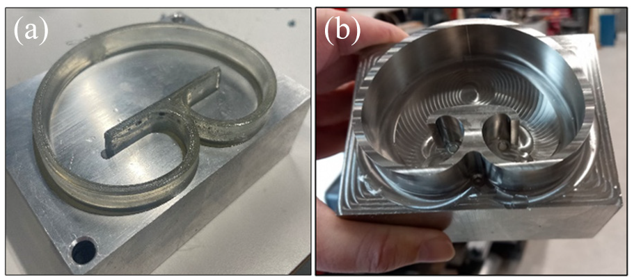
A demonstration of manufactured resilient biasing device using: (a) injection moulded polymer; (b) CNC milled Ti6Al4V.
For low-volume production or specialised applications, additive manufacturing provides the necessary design freedom. Metal additive manufacturing methods such as laser powder bed fusion and binder jetting for ceramics are particularly suitable, while polymer and elastomer devices can be produced via 3D printing. Additionally, conventional and non-conventional machining methods, including CNC milling and electrical discharge machining can offer precision fabrication options. These are particularly beneficial for delivering better fatigue performance as surface finish influences fatigue performance. As demonstrated in Figure 25(b), a Ti6Al4V resilient biasing was successfully milled to achieve a surface finish with an average surface roughness of Ra < 1 µm. The device’s geometry also lends itself to fabrication via laser or waterjet cutting, which may be practical solution for larger devices.
Application-oriented prototypes
The aim of this section is to demonstrate the practical applicability of the resilient biasing device, rather than to explore the scientific principles in depth. One of the possible applications of the resilient biasing device is in comfort-oriented products. These include beds, seats, sofas, chairs, shoes, and cushions designed to support various parts of the body (neck, back, legs, arms). Figure 26 illustrates a zoned king size mattress prototype, which integrates resilient biasing devices of varying thicknesses and stiffness levels. Stiffer resilient biasing devices (red) are positioned along the edges to prevent users from rolling off the bed. The softest resilient biasing devices (white) are placed in the hip and shoulder regions to allow for greater local deformation, helping to maintain spinal alignment, which is an indicator of healthy sleep posture. Medium-stiffness resilient biasing devices (blue) are distributed throughout the remaining areas of the mattress. One of the sides of the mattress features single-loop spirals, while the other side uses double-loop spirals. This design effectively doubles the stiffness on one side, increasing firmness while maintaining similar stress levels within the devices for the same displacements. The resilient biasing devices are connected using rigid rods, allowing the entire unit to be rolled up, which could be an advantage for transportation. Unlike conventional open-coil or pocket spring mattresses made from steel, this prototype is constructed from 3D-printed PETG, demonstrating the potential for cost-effective production using extruded or injection-moulded polymer materials. This included recyclable, recycled, and/or biodegradable polymers, contributing to the mattress design's overall sustainability. Additionally, the open structure of the device promotes ventilation, contributing to a cooler sleeping environment, which is another important factor in sleep quality. A layer of foam is applied on top of the resilient biasing devices to provide the desired softness. This prototype combines the localised deformation benefits of pocket springs with the breathability of open-coil designs. Furthermore, it is compatible with scalable, cost-effective manufacturing processes and sustainable materials, setting it apart from traditional spring and foam mattresses. Its adjustable stiffness and ease of assembly can make it well-suited for delivering customised comfort tailored to individual sleep and body needs.
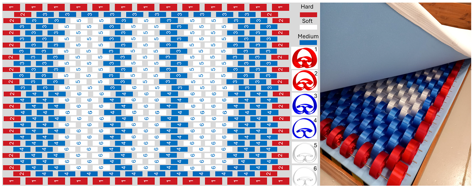
Layout design of a king size mattress and a physical prototype using connected resilient biasing devices.
The same principle of using the resilient biasing device was applied in the design of cushions tailored for various parts of the body. Figure 27 presents several prototypes where the resilient biasing device was utilised for cushioning and support applications. One example is an armchair, in which both the seat and back cushions are constructed using resilient biasing devices connected by flexible elastic cords. The armrests also incorporate resilient biasing devices to provide comfortable arm support. A separate seat cushion prototype features smaller resilient biasing devices made of TPU applicable to passenger seat. In this design, the front resilient biasing devices (blue) are approximately half as stiff as those at the back (black), while the middle resilient biasing device (red) offer medium stiffness. This stiffness gradient reflects the typical load distribution: the rear of the cushion bears more weight, while the front, supporting the legs, experiences approximately three times less load. Figure 27 also show resilient biasing devices integrated into shoe soles to offer design options for various purposes: comfort, where pressure is uniformly distributed; running performance, where elastic energy is rapidly released; and health considerations, such as orthopaedic soles. A hybrid pillow prototype is also shown to demonstrate the integration of resilient biasing devices in a pillow to provide support during sleep. Additionally, a finger/forearm strengthening device prototype showcases potential applications in sports and rehabilitation. Other applications include neck travel cushions, backrest cushions, and leg rest cushions. These examples highlight the versatility and adaptability of resilient biasing devices across a wide range of ergonomic and comfort-focused applications.
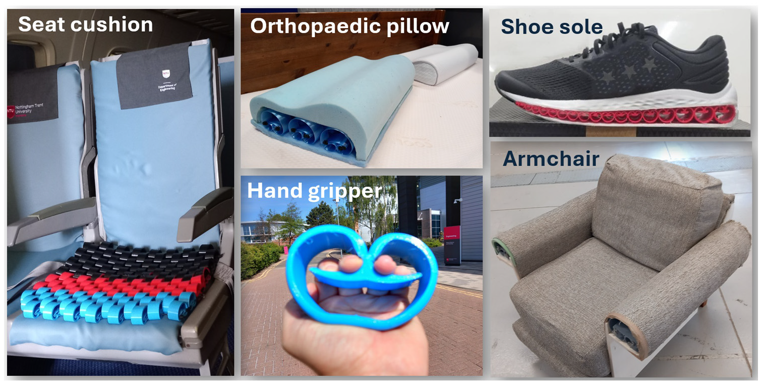
Exemplars of comfort-focused application prototypes using resilient biasing devices.
The ability of the resilient biasing device to provide structural support and isolate vibrations makes it a strong candidate for use in suspension systems. In addition to its application in the baby incubator prototype, a new primary suspension system was prototyped for a scaled-down railway bogie, as illustrated in Figure 28. In this prototype, the resilient biasing device was 3D printed using PETG. The central section of the device was designed to accommodate an axle and bearing, effectively simplifying the conventional primary suspension system, which typically requires a separate axlebox. This integrated design concept, embedding the axle and bearing within the resilient biasing device, could open up new possibilities for innovative transport applications. The central space, where the axle is housed, can also be used to attach a damper to the top of the resilient biasing device, enabling the device to function as a shock absorber too. Furthermore, the use of multiple materials in the construction of the resilient biasing device could enhance its damping capabilities, although this would require further research investigation. In a similar fashion, the resilient biasing device could be employed as an actuator for vibration reduction in manufacturing environments and other industrial settings.
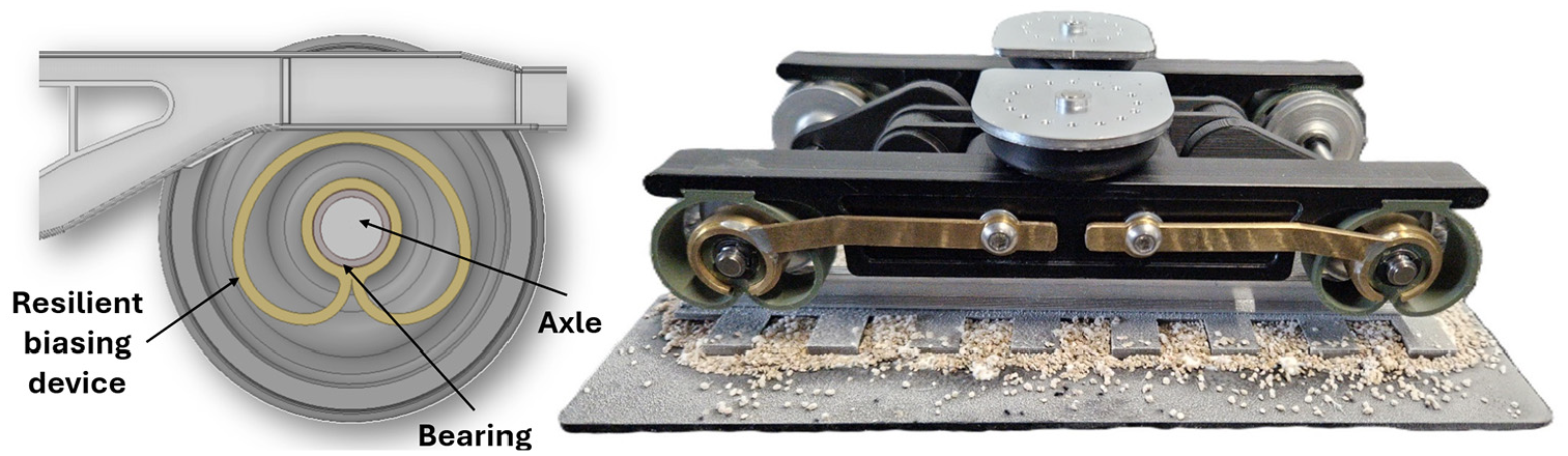
An example of an integrated axle and bearing into a resilient biasing device, applied to a scaled-down prototype of a railway bogie.
Another advantage of the resilient biasing device is its ability to extend under compression and contract under tension. As mentioned in section ‘Results and analyses’, this additiona functionality could open up possibilities for applications such as valves and fasteners. Beyond mechanical applications, the resilient biasing device could also be applied to sensor technologies. When fabricated from piezoelectric materials, it can generate voltage in response to applied stress. Additionally, it may find applications in energy storage, energy harvesting, and energy absorption due to impact, offering a platform for future innovations and reserach.
Conclusions
This research study investigated the fundamental mechanical characteristics of the resilient biasing device using experimental, analytical, and finite element analysis (FEA) approaches. The results highlighted its multidirectional stiffness, vibration isolation capabilities, and potential for diverse engineering applications. The following conclusions were derived from this research:
New analytical closed-form formulations were developed, establishing relationships between geometrical parameters (height, extrusion width, thickness), material properties (Young’s modulus, stress limit), and key mechanical performances (deformation, force, stiffness, elastic energy, specific elastic energy, and natural frequency).
The resilient biasing device provides multidirectional stiffness, as defined by the analytical closed-form solutions developed in this study. It is stiffer under tension than compression, flexible in one transverse direction towards the length, and stiffest in the transverse direction towards the extrusion width.
The thickness and height of the resilient biasing device significantly impact stiffness and allowable displacement at specified stress limits, making them crucial design factors. The spiral type constructing the device also plays a vital role in determining its mechanical behaviour.
The ability to predict mechanical performance indicators using the developed analytical formulations and validated FEA models can expedite product development and minimise lead times, which is critical in engineering design.
Experimental and FEA approaches demonstrated that the resilient biasing device could achieve a 90% vibration reduction when applied to a prototype baby incubator, showcasing its vibration isolation capabilities.
The device can deliver a large amount of elastic energy for materials with high elastic limits or yield strengths and a low modulus of elasticity.
Prototypes using resilient biasing devices were developed to demonstrate its applicability in supporting and suspending loads (e.g. seats, mattresses, cushions, suspension system).
The adaptability of geometrical parameters (height, length, extrusion width, spiral type and multi-loops), along with the ability to use a wide range of materials and employ mass production, makes the resilient biasing device suitable for various commercially viable applications.
Its ability to increase in length under compression and vice versa under tension suggests potential use in fasteners, valves, and other engineering applications.
This study provides a foundational understanding of the resilient biasing device’s mechanical properties and proposes both analytical and FEA solutions to facilitate product design. Future studies could explore the impact of various materials, manufacturing processes and environmental conditions (e.g. temperature) on the device's mechanical performance, including fatigue and creep. Additionally, research into performance across diverse product designs and applications could further expand its utility.
Footnotes
Declaration of conflicting interests
The author(s) declared no potential conflicts of interest with respect to the research, authorship, and/or publication of this article.
Funding
The author(s) received no financial support for the research, authorship, and/or publication of this article.