
Abstract
An analytical elastostatic stiffness modeling approach for kinematically redundant parallel mechanisms (KR-PMs) according to screw theory and the second theorem of Castigliano is proposed. The 2-UPR/PRPU and 2-PUPR/PRPU KR-PMs are used as two examples of KR-PMs to validate the precision of the proposed approach. The relative error is less than 1.55% when the theoretical model is compared to the FEA model. The PM’s stiffness performance is assessed using the minimum linear displacement stiffness performance index, which is based on the theoretical model. By integrating Particle Swarm Optimization (PSO) with polynomial fitting technology, an analytical mapping model of the response surface between the optimal actuating distances and the moving platform (MP)’s given position and orientation is established. It is demonstrated that 2-UPR/PRPU and 2-PUPR/PRPU KR-PMs can significantly enhance the stiffness performance when compared to the stiffness performance of 2-UPR/RPU PM.
Introduction
Compared with serial mechanisms, PMs have obviously advantages such as rapid speed, high rigidity, big bearing capacity and excellent dynamic performances. PMs have recently become widely used in industrial application, such as parts sorting, motion simulation, medical surgical robots, and complex parts processing.1–4 However, PMs may encounter problems such as small workspaces and singularities in industrial applications.5–7 Therefore, it is an important issue to increase the workspaces and avoid singularities with redundancy.
The redundancy of PMs is mainly divided into two types: kinematic redundancy and actuation redundancy. Kinematic redundancy means that the overall DOF of the mechanism is greater than the number of independent motions of the moving platform. Actuation redundancy means that the number of independent actuators of the mechanism is greater than the overall DOF of the mechanism. To increase workspaces and avoid singularities, researchers have proposed some configurations of KR-PMs. In 2004, Wang and Gosselin 8 designed three new types of KR-PMs: planar 4-DOF mechanism, spherical parallel mechanism and spatial 7-DOF Stewart platform. Ebrahimi et al.9–11 proposed a 3-PRRR planar KR-PM according to 3-RRR PM. After that, Gosselin and Schreiber12–14 proposed a variety of KR-PMs, and the kinematic modeling, workspace and singularity have been analyzed. The results show that the KR-PMs have significant advantages of avoiding singularities, increasing workspaces and improving the kinematic performances of the mechanisms. Isaksson 15 proposed three types of kinematically redundant planar PMs, which can avoid singularities effectively by selecting the appropriate actuators. In 2017, Qu and Guo 16 proposed a new kinematically redundant planar PM.
The elastostatic stiffness performance is one of the most important performances of PMs. Since the elastostatic stiffness modeling is the basis of stiffness performance analysis, it is necessary to carry out the PM’s elastostatic stiffness modeling during the design stage. The elastostatic stiffness modeling methods of PMs contained these types: finite element method and assume mode method,17–19 matrix analysis method,20,21 virtual joint method,22,23 screw 1 theory method,24,25 and strain energy method.26,27 The precision of the FEM is high, but the model needs to be reconstructed and divided with high calculation cost for different configurations, which is inadequate for performance analysis. The method of matrix structure analysis does not require grid division, but it involves high order matrix operations and several deformation compatibility equations, making it improper for analytical elastostatic stiffness modeling. The virtual joint method needs to deal with redundant spring restrictions, which makes the stiffness model more difficult. The screw theory method reduces the dimension of the limb constraint screws system and improves the calculation efficiency. The strain energy method can analyze the PM’s stored strain energy under external wrenches with definite physical meaning. However, fewer scholars research the elastostatic stiffness modeling of KR-PMs. Shin and Lee 28 proposed an elastostatic stiffness modeling method of planar KR-PMs. Jamshidifar et al. 29 established an elastostatic stiffness model of the kinematically redundant constrained cable parallel robot. Wang et al. 30 deduced a KR-PM’s stiffness model and natural frequency using the matrix structure analysis method. Zhang et al. 31 discussed the stiffness matrix for a 3-DOF planar KR-PM.
To estimate the PM’s stiffness performance, researchers have defined a few stiffness indices, such as eigenvalue index, determinant value index, main diagonal index of stiffness matrix, trace of matrix, virtual work index, etc.32–35 However, the above stiffness indices except virtual work index are based on algebraic properties with unclear physical meanings, and the dimensions of the stiffness matrix are not uniform, which may lead to interpretation errors. The virtual work index describes the stiffness performance using energy. Although it can avoid the dimensions of the stiffness matrix are not uniform, it is related to the external wrenches of the mechanism.
An analytical elastostatic stiffness modeling approach of KR-PMs according to the Castigliano’s second theorem and screw theory has been put forward. The approach has been validated by 2-UPR/PRPU and 2-PUPR/PRPU KR-PMs. Combining PSO and polynomial fitting technology, the mapping model of the response surface between the optimal actuating distances and the position and orientation of the MP is established. According to the obtained theoretical stiffness model of 2-UPR/PRPU and 2-PUPR/PRPU KR-PMs, the minimum linear displacement stiffness performance index 36 is used to estimate the stiffness performance. Compared with the stiffness performance of 2-UPR/RPU PM, it is shown that 2-UPR/PRPU and 2-PUPR/PRPU KR-PMs can significantly enhance the stiffness performance.
Analytical elastostatic stiffness modeling of KR-PMs
Modeling process
Figure 1 depicts the general model of the KR-PMs. The KR-PM contains n limbs connected to the MP. The kinematically redundant limb contains multiple actuating joints, while the non-redundant limb only contains one actuating joint. To facilitate the establishment of analytical elastostatic stiffness model, the fixed coordinate system O-xyz, the moving coordinate system o-uvw and the limb coordinate system Bi-xiyizi were set as indicated in Figure 1. The external wrenches imposed on the MP can be simplified as a screw
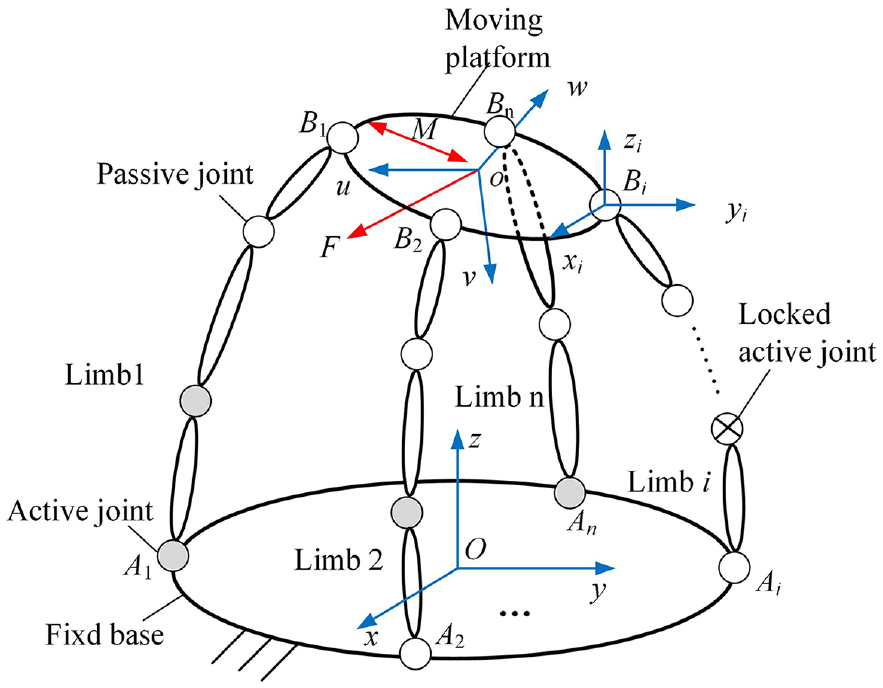
The general model of KR-PMs.
The modeling process of the analytical elastostatic stiffness of KR-PMs is as indicated in Figure 2, and the detailed steps are outlined as follows:
Step 1: The i-th limb twist system is established based on the screw theory and the actuating force screw
Step 2: Exploiting strain energy method, the i-th limb analytical expression of strain energy Ui is obtained;
Step 3: The elastic deformation
Step 4: According to the connection among the elastic deformation
Step 5: The deformation compatibility equation and the balancing equation of the MP are created based on the virtual work principle;
Step 6: In accordance with the stiffness matrix and deformation compatibility equation of each limb, the overall stiffness matrix and the constraint wrench system amplitude of the KR-PM are derived.
Step 7: The elastostatic stiffness performance of the KR-PM is related to the configuration. Thus, it can be improved by adjusting the actuating distances given position and orientation of the MP.
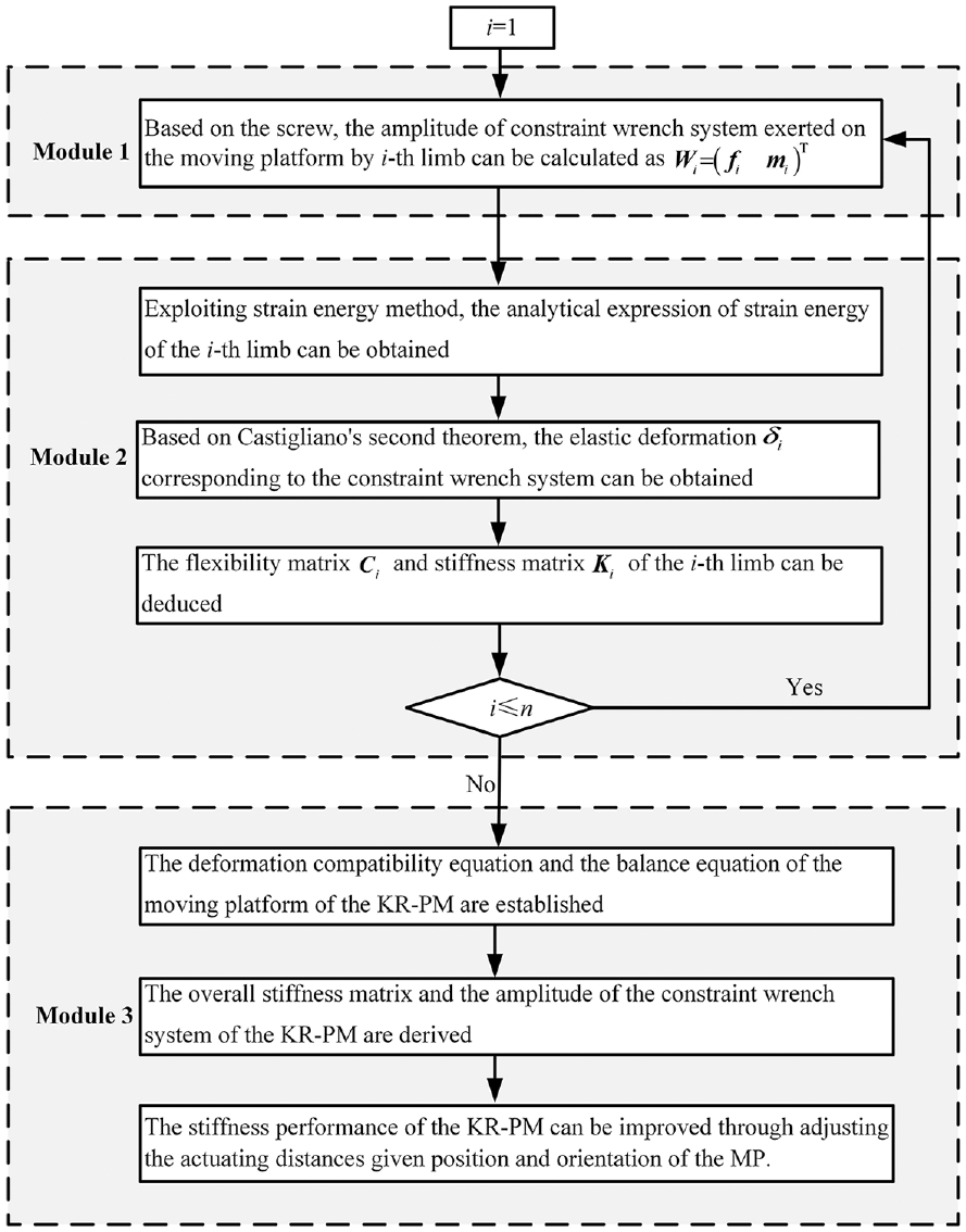
Flow chart for elastostatic stiffness modeling of KR-PMs.
Limb stiffness matrix
The mapping relationship between the constraint wrench system amplitude and the associated elastic deformation is represented by the limb stiffness matrix. The limb stiffness matrix shares the same dimension as the constraint wrench system. For a lower-DOF KR-PM, as long as there are exist passive joints, the limb stiffness matrix is a compact stiffness matrix. Assume that the i-th limb contains (6-mi + 1) constraint force/couple, that includes a force screw fij
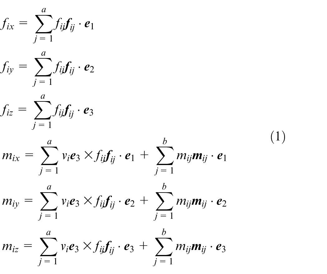
where
The i-th limb strain energy is determined based on material mechanics,
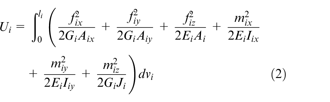
where li stands for the i-th limb length, Ei and Gi stand for the elastic and shear moduli, respectively; Aix and Aiy stand for the cross section’s effective shear area along the xi- and yi-axes, respectively; Ai represents the cross section area; Iix and Iiy stand for the cross section inertia moment beside the xi- and yi-axes, and Ji represents the polar inertia moment.
As stated in the second theorem of Castigliano, the deformation vector
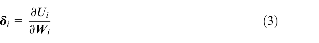
where
Equation (3) can be expanded as
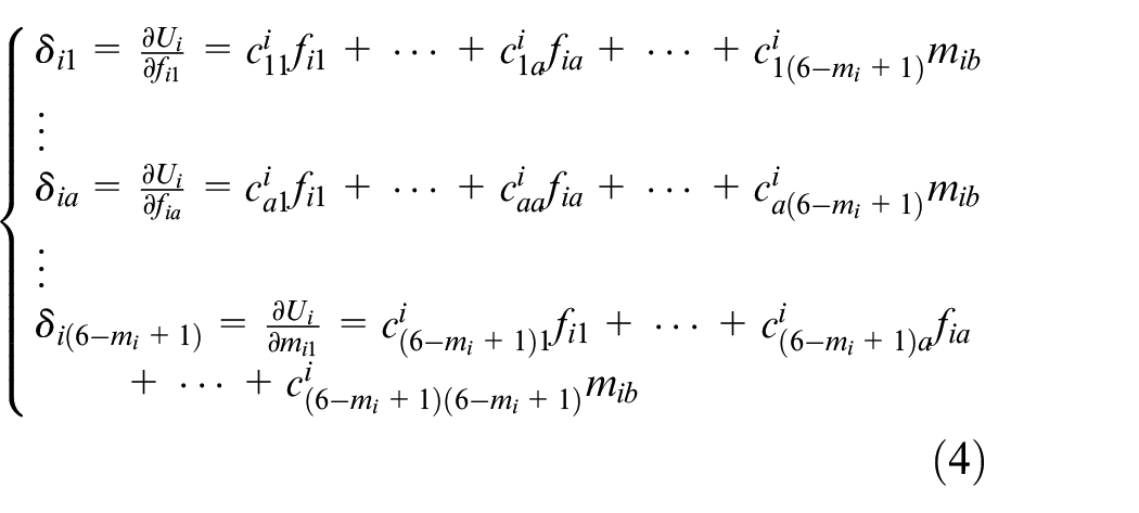
In a matrix, equation (4) is written as

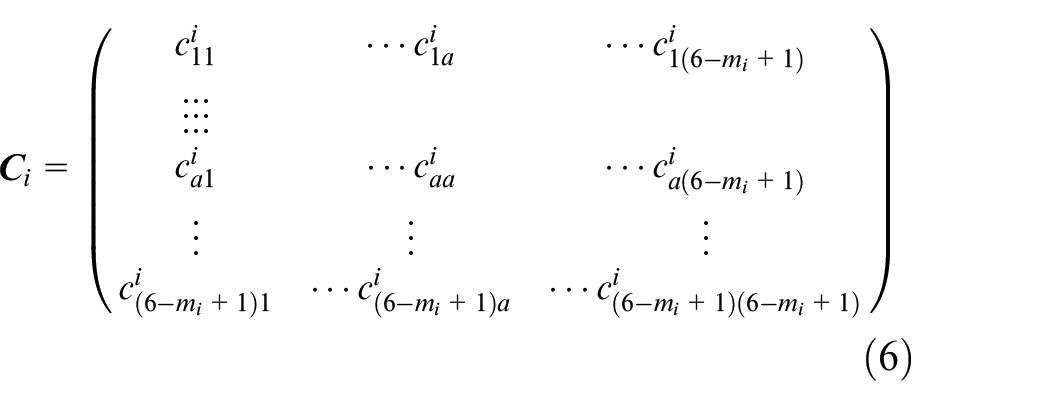
where
Thus, by flipping the flexibility matrix, it is possible to get the limb stiffness matrix as

As a result, the computations above can be used to generate the analytical expressions of the flexibility matrix and stiffness matrix of each limb.
Overall stiffness matrix and amplitude of constraint wrench system
By assembling all of the limb stiffness matrices together, the overall KR-PM’s stiffness matrix may be found. Non-overconstrained PMs and overconstrained PMs are the two categories into which KR-PMs fall. The overall stiffness matrix can be determined directly from the balance equations of the MP if the KR-PM is a non-overconstrained PM, the quantity of constrained responses and the quantity of balancing equations are equal. If the KR-PM is an overconstrained PM and there are more constrained reactions than equilibrium equations, then there must be an equal number of deformation compatibility equations inserted in order to derive the overall KR-PM’s stiffness matrix. In the fixed coordinate system, the balancing equation for the MP can be expressed as follows
where
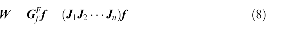
The deformation vector
where
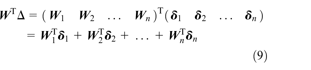
Combining equations (8) and (9), the deformation compatibility equation between

Equation (5) can be rewritten as

Substituting equations (10) and (11) into equation (8), one obtains
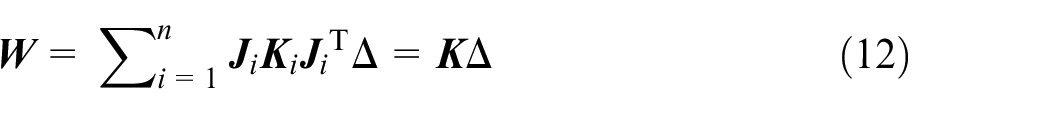
Therefore, the overall elastostatic stiffness matrix of a KR-PM is
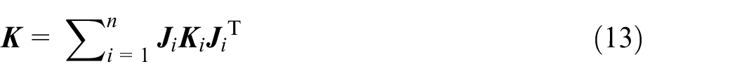
Besides, the amplitude of the constraint wrench system in each limb can thus be obtained by combing equations (10)–(13).

Example 1: 2-UPR/PRPU KR-PM
Modeling of analytical elastostatic stiffness
To validate the analytical elastostatic stiffness approach of KR-PMs, 2-UPR/PRPU KR-PM has been taken to set up the theoretical model in this section. The 3-DOF non-redundant 2-UPR/RPU PM is proposed by Li and Herve. 37 According to 2-UPR/RPU PM, 2-UPR/PRPU KR-PM has been designed based on Lie group theory (for more details, see Wu et al. 38 ). Hence, the 2-UPR/RPU PM has been taken as a reference group to show the improvement of stiffness performance of 2-UPR/PRPU KR-PM. For the stiffness performance analysis of this PM, we can obtain the actuating distance q4 using the optimization algorithm according to the best stiffness performance.
Structure description
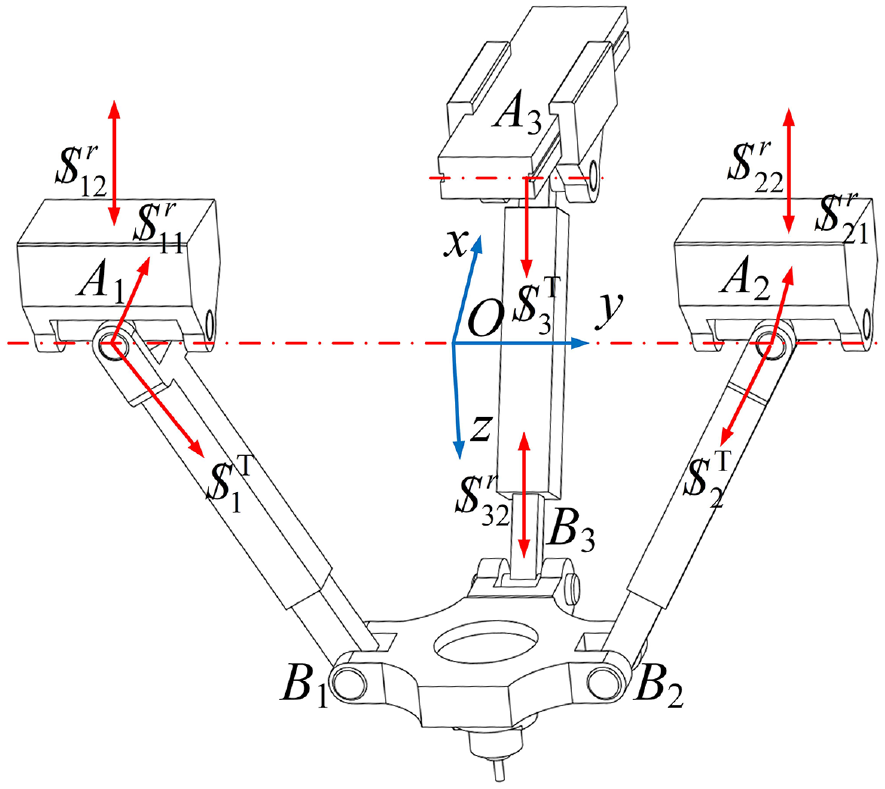
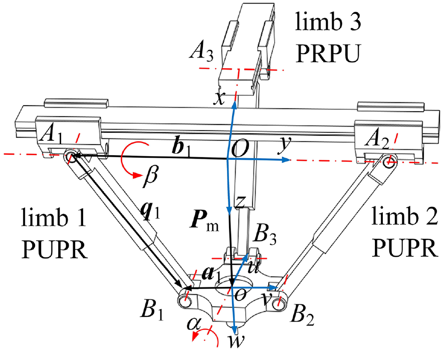
The 2-UPR/PRPU KR-PM has three limbs, limb 1 and limb 2 are two non-redundant limbs, and limb 3 is a kinematically redundant limb as shown in Figure 3. The first and second limbs are fixedly connected with the framework through the U joints, and the third limb is fixedly connected with the framework through the guide. The first and second limbs take the only P joint as the actuator, and the third limb takes two P joints as the actuators to update the MP’s position and orientation.
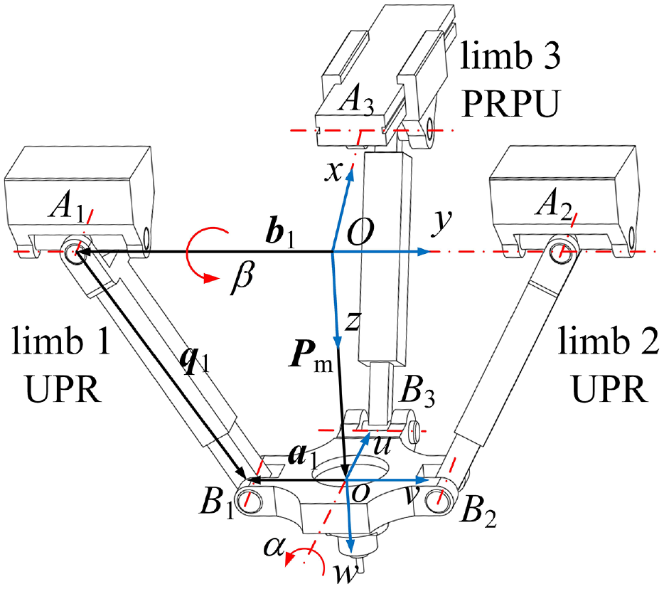
Schematic diagram of 2-UPR/PRPU KR-PM.
A1, A2 represent the U joint’s rotation center in the first and second limbs, respectively, and A3 represents the R joint’s rotation center in the third limb. B1, B2 represent the R joint’s rotation center in the first and second limbs, respectively, and B3 represents the U joint’s rotation center in the third limb. At the midway of A1A2, the fixed coordinate frame O-xyz is fixed. The x- and y-axes are vectors along OA3 and OA2, and the right-hand rule can be used to get the z-axis. Besides, the u- and v-axes of the moving coordinate frame o-uvw are vectors along oB3 and oB2, and the w-axis is vertical to the MP. Additionally, the 2-UPR/PRPU KR-PM’s dimension parameters are outlined below: OA1 = OA2 = lb, OA3 = q4, oB1 = oB2 = oB3 = la.
Inverse kinematics
For modeling and performance analysis of elastostatic stiffness, the inverse kinematics is required. The 2-UPR/PRPU KR-PM’s inverse kinematics can be established using the relationship between the input variables qi (i = 1,2,3,4) and the output parameters (

where Pm represents the position vector Oo;
The rotation matrix
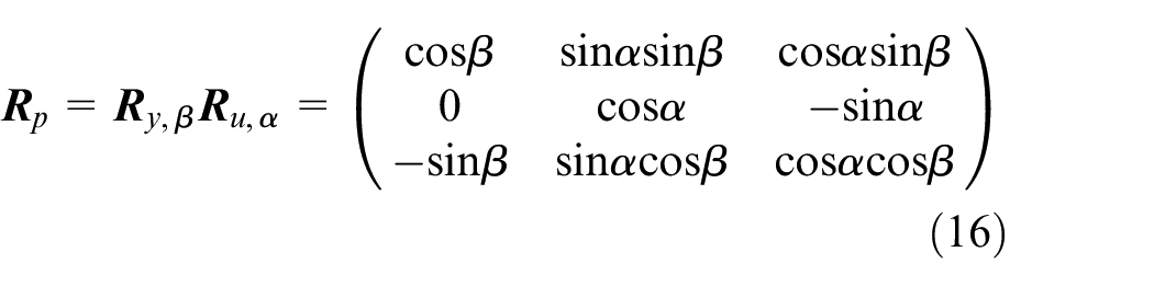
The following equation yields the coordinate of point o in the fixed coordinate frame.

Combining equations (15)–(17), the inverse position solution of 2-UPR/PRPU KR-PM is derived as
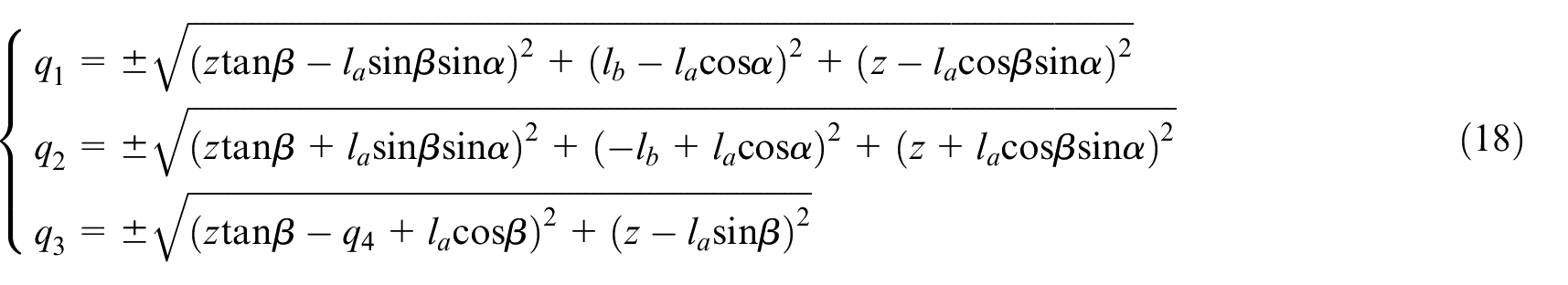
Through equation (18), we can easily obtain the input variables qi (i = 1,2) of first and second limbs given the output parameters (
Stiffness matrix of UPR limb and PRPU limb
According to the limb stiffness modeling approach, the UPR limb’s actuating force screw

where
The constraint wrench system of 2-UPR/PRPU KR-PM.
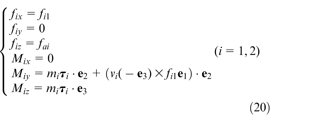
Figure 5(a) shows the constraint wrench system on the UPR limb. fai, fi1, and mi1 represent the amplitudes of the actuating force screw
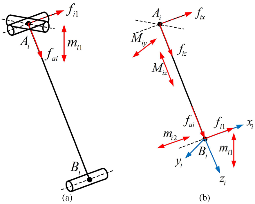
The UPR limb’s constraint wrench system: (a) force/moment state and (b) projection state.
Any cross section of the UPR limb’s internal force/moment can be stated as
where
Therefore, the UPR limb’s strain energy can be represented as

The second theorem of Castigliano states that the limb’s infinitesimal elastic deformation under the constraint wrench system is
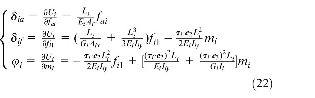
Equation (22) is expressed in matrix form as

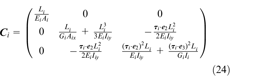
where
Therefore, according to equation (24), the UPR limb’s stiffness matrix is

The PRPU limb’s actuating force screw
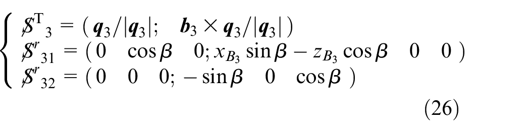
where
The constraint wrench system and limb coordinate system of the PRPU limb are indicated in Figure 6. The y3-axis runs parallel to the axis of the R joint, z3-axis runs along the vector A3B3, and the x3-axis on the basis of the right-hand rule. The fa3, f31, and m31 denote the amplitudes of the actuating force screw
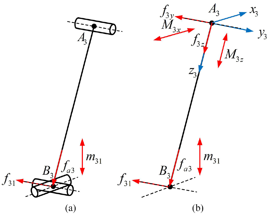
The PRPU limb’s constraint wrench system: (a) force/moment state and (b) projection state.
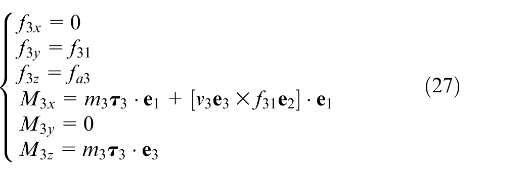
In the limb coordinate system, the force/moment in any section of PRPU limb is
The PRPU limb’s strain energy on the basis of the constraint wrench system can be stated as
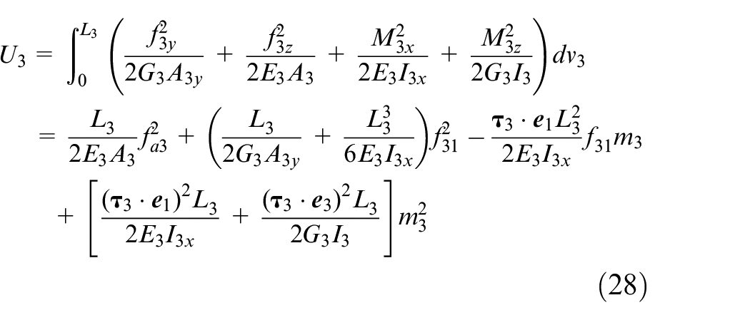
Thus, the PRPU limb’s flexibility matrix can be obtained as
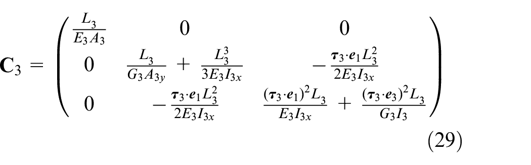
Similarly, the stiffness matrix

Overall stiffness matrix of 2-UPR/PRPU KR-PM
According to the constraint wrench system distribution of UPR and PRPU limb, the reaction forces exerting on the MP is accessible as depicted in Figure 7. W = (

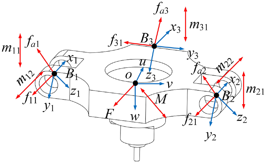
Forces imposed on the MP.
where
Equation (31) shows that the elastostatic stiffness performance is related to the KR-PM’s configuration given position and orientation of the MP. The optimal actuating configurations can be obtained using the optimization algorithm according to the best stiffness performance. Besides, according to equations (11) and (14), it can be deduced that the amplitude of the actuating force vector in each limb of this PM is

Modeling verification
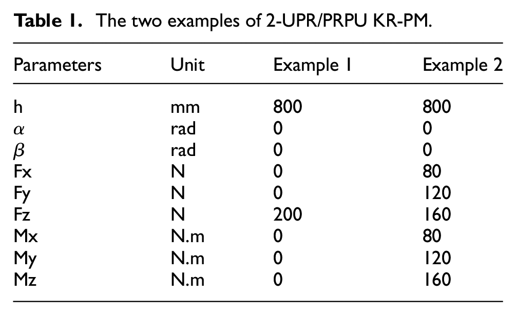
A simplified model of the 2-UPR/PRPU KR-PM is established using ANSYS software to confirm the accuracy of the theoretical model. The FEM considers the fixed base, MP, and joints to be rigid and assumes that all of the limbs have the same material’s circular cross sections. The limbs are also assumed to have deformable beam elements. The physical parameters of this PM are: la = 260 mm, lb = 390 mm, elastic modulus E1 = E2 = E3 = 210 GPa, shear modulus G1 = G2 = G3 = 80 GPa, the diameter of the limb cross section d1 = d2 = d3 = 100 mm, the distance h = 800 mm denotes the operating height Oo of MP.
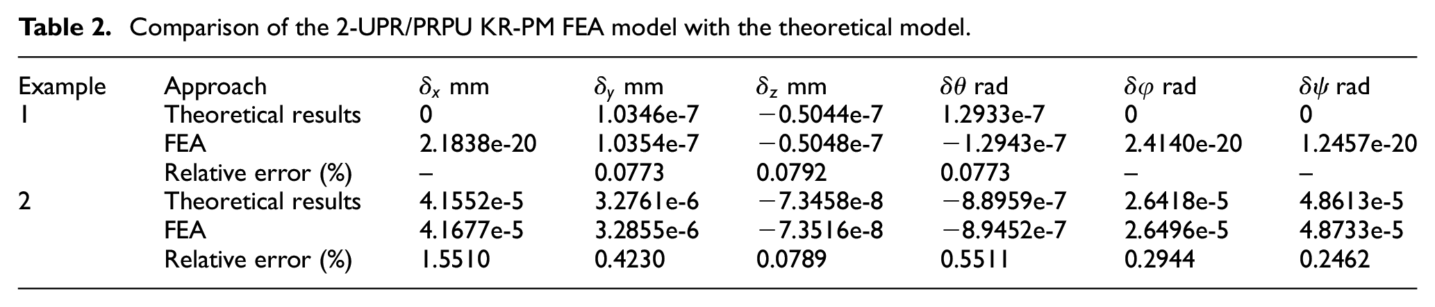
To save calculation time, two examples are selected for verification as shown in Table 1. Figure 8 displays the findings of the center point of the MP’s linear and angular deformation. Table 2 also includes comparison findings between the theoretical model and the FEA model. The findings of the two models are found to be largely comparable, and the relative error is shown to be within 1.55%, demonstrating the precision of the theoretical model.
The two examples of 2-UPR/PRPU KR-PM.
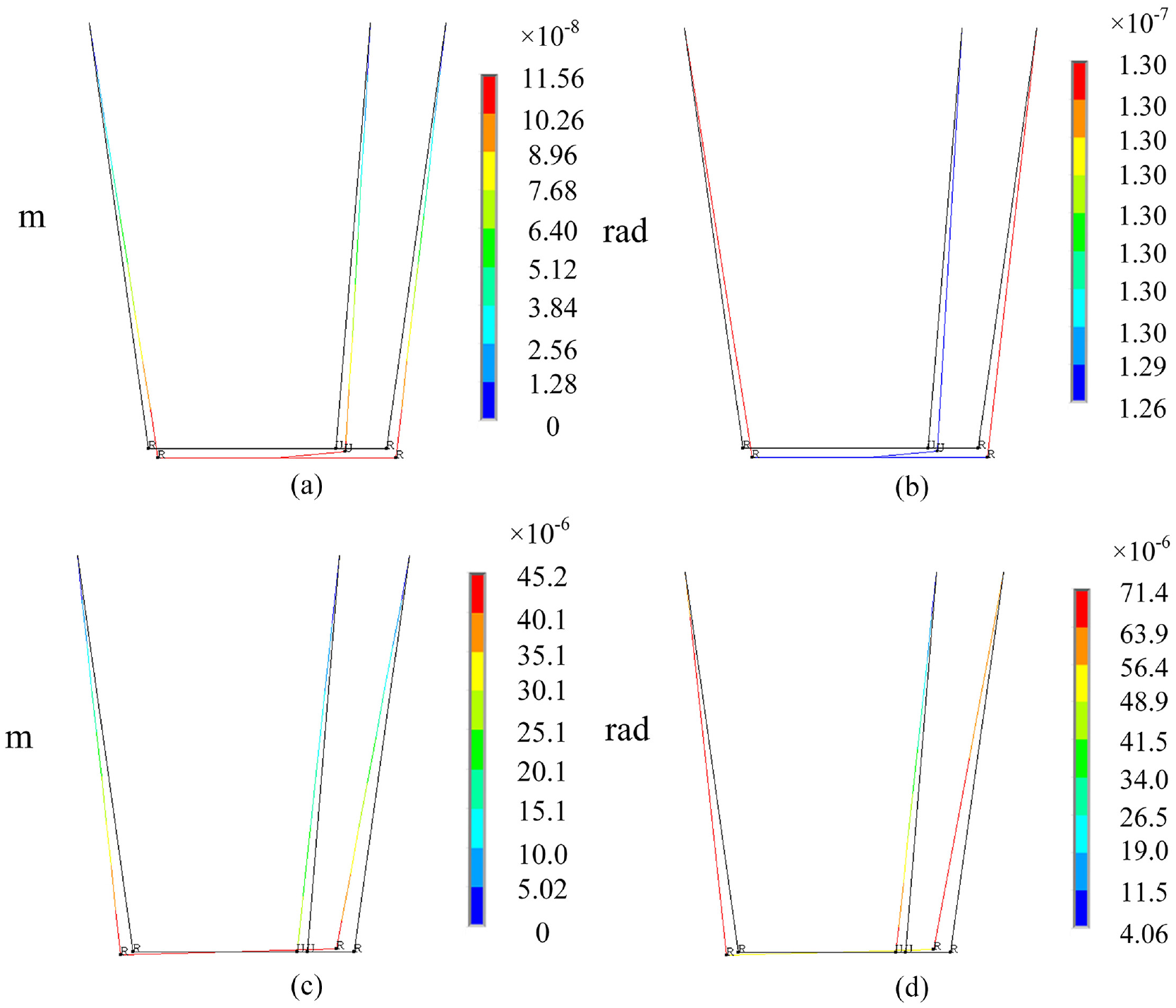
2-UPR/PRPU KR-PM’s deformation results: (a) example 1’s linear deformation, (b) example 1’s angular deformation, (c) example 2’s linear deformation, and (d) example 2’s angular deformation.
Comparison of the 2-UPR/PRPU KR-PM FEA model with the theoretical model.
Performance analysis
Stiffness index
According to the elastostatic stiffness model, the minimum linear displacement stiffness index 36 has been used to assess the PM’s stiffness performance because PMs mainly suffers the external force wrenches when parts processing. Unlike the above stiffness indices,32–35 the minimum linear displacement stiffness performance index evaluates the mechanism’s minimum linear stiffness when it is subjected to external force wrenches. It is simple to calculate and has a definite physical significance.
Under the external wrenches, the MP’s center point’s minuscule deformation vector is

where
In general, a PM’s overall compliance matrix can be stated as
where
The PM’s maximum compliances under an external force can be expressed as
where
Taking the reciprocal of equation (35), the minimum linear displacement stiffness performance of the PM under external forces wrenches can be obtained as

Stiffness optimization algorithm
In general, it is challenging to compute stiffness optimization in real-time. To quickly determine the optimum stiffness’s position given various positions and orientations of the MP, this paper combines PSO and polynomial fitting technology to establish the analytical mapping model of the response surface between the optimal actuating distances and the positions and orientations. The response surface mapping model based on polynomial is defined as
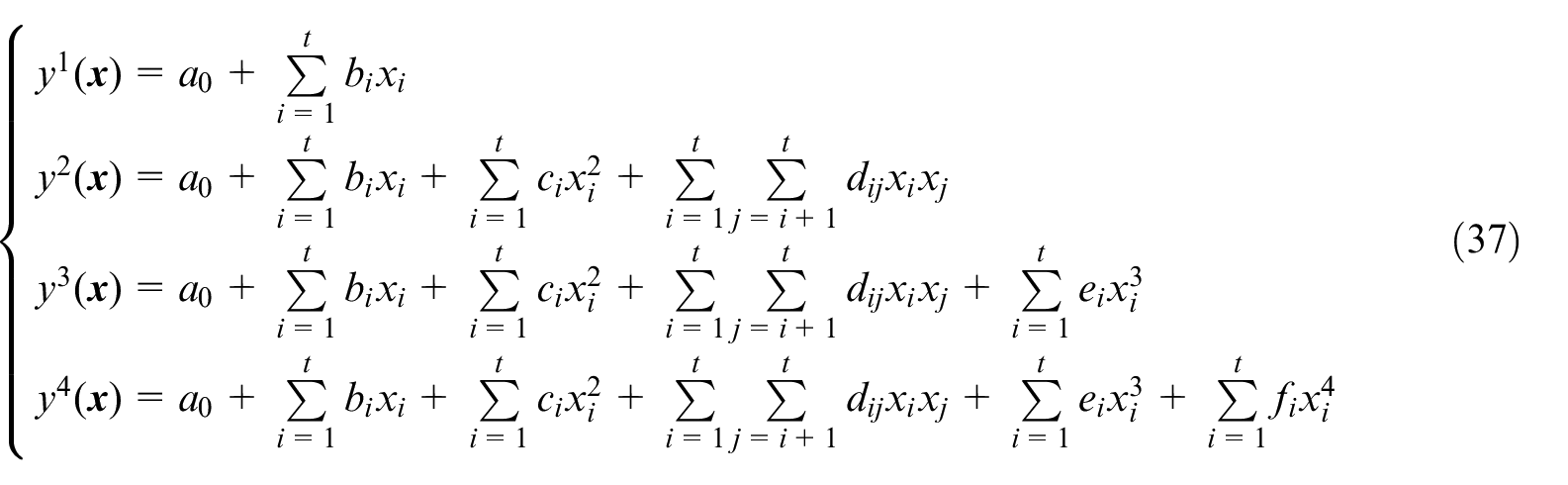
where
The regression coefficients of the polynomial response surface analytical mapping model can be obtained by decreasing the square of the discrepancy between the observed and estimated the values.
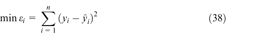
where
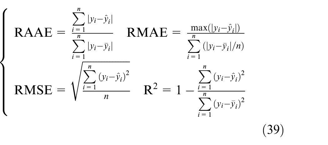
To assess the precision of fitting polynomial, the performance indices of fitting function are used. The most commonly used performance indices are RAAE, RMAE, RMSE, and R2, which are indicated as
Without losing generality, the response surface model (RSM) between the optimal actuating distance q4 and the MP’s position and orientation is established with the operating height h = 800 mm and the ranges of two rotational angles were set as
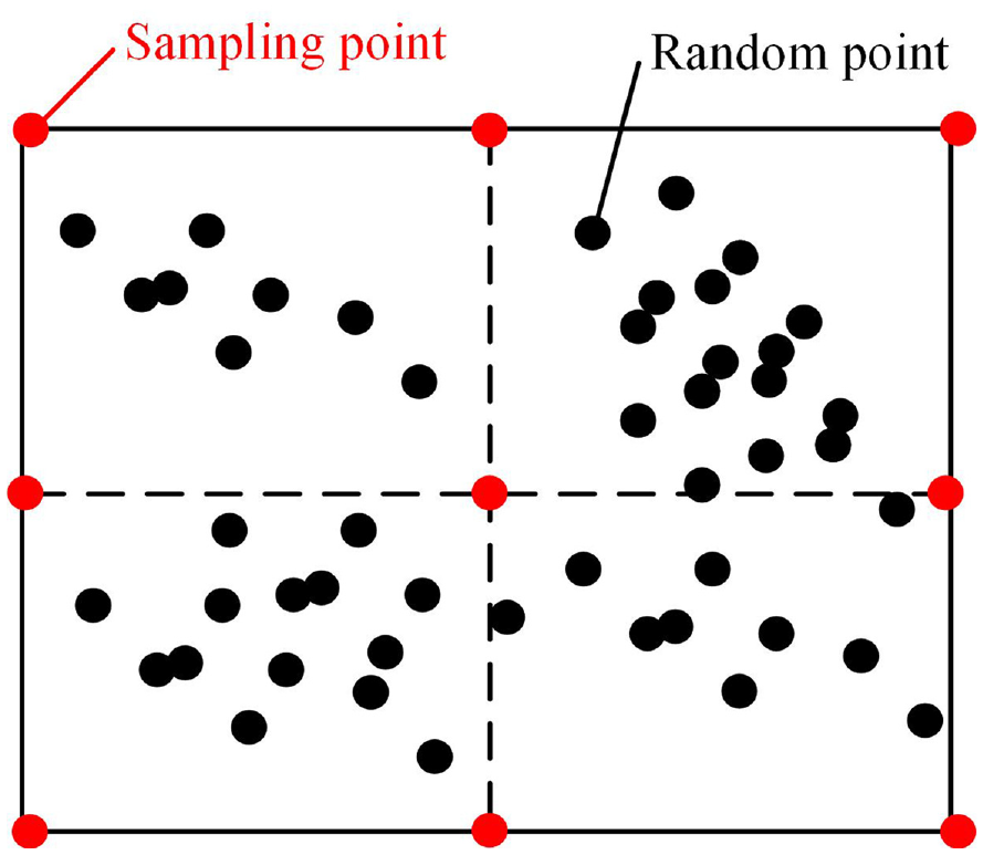
Schematic diagram of the sampling points.
Stiffness performance comparison
Comparing with the stiffness performance of non-redundant PM, the physical parameters of 2-UPR/PRPU KR-PM are selected as same as 2UPR-RPU PM 39 : la = 260 mm, lb = 390 mm, elastic modulus E1 = E2 = E3 = 210 GPa, shear modulus G1 = G2 = G3 = 80 GPa, the diameter of the limb cross section d1 = d2 = d3 = 100 mm, the operating height h = 800 mm. The mathematical model of 2-UPR/PRPU KR-PM is defined as
where
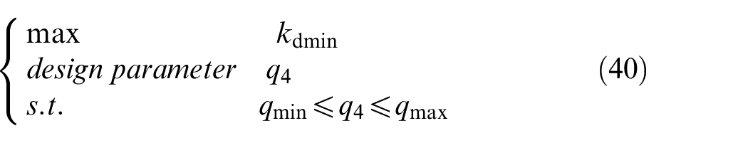
To increase the fitting precision, the sampling points is 100 in this paper. The accuracy of the polynomial RSM obtained by external validation using the 30% sampling points, and the results as listed in Table 3. Table 3 shows that with the increase of the polynomial degree, the accuracy of the RSM is not significantly improved, but the calculation efficiency decreases with the increase of the unknown amount of the required fitting regression. The acceptance precision of polynomial RSM is that RMSE value is below 0.2 and the R2 value is above 0.9. 40 Considering the accuracy and computational efficiency together, the quartic polynomial is selected to establish the RSM between the optimal actuating distance q4 and two orientation angles in this paper.
The accuracy of the polynomial RSM.
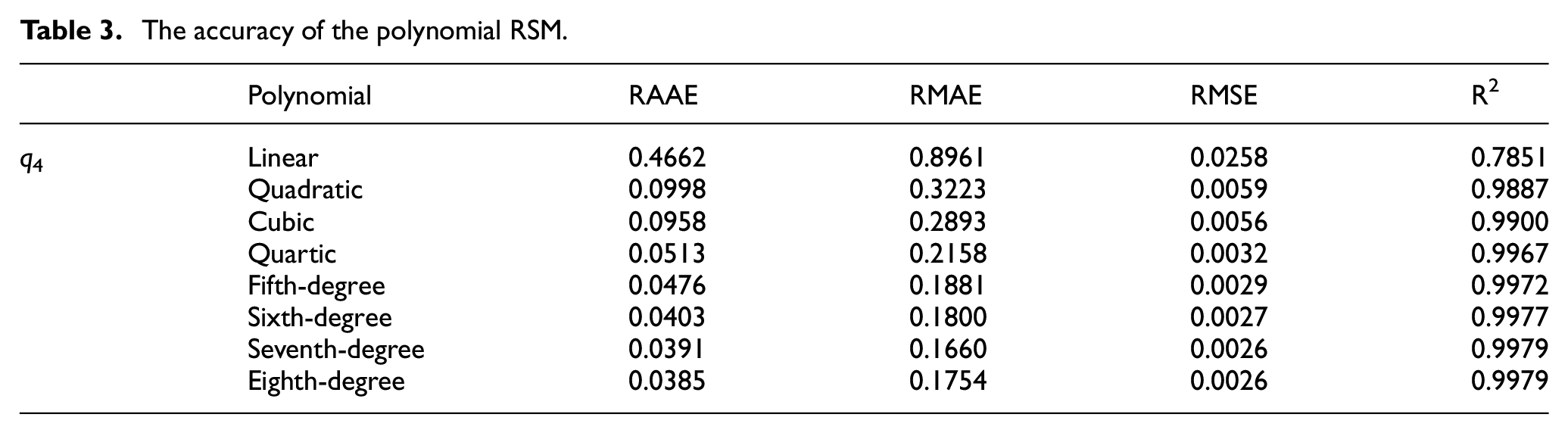
Figure 10 shows the distribution of the optimal actuating distance q4 of 2-UPR/PRPU KR-PM. It can be seen from the figure that the optimal actuating distance q4 changes with the MP’s orientation. The orientation angle
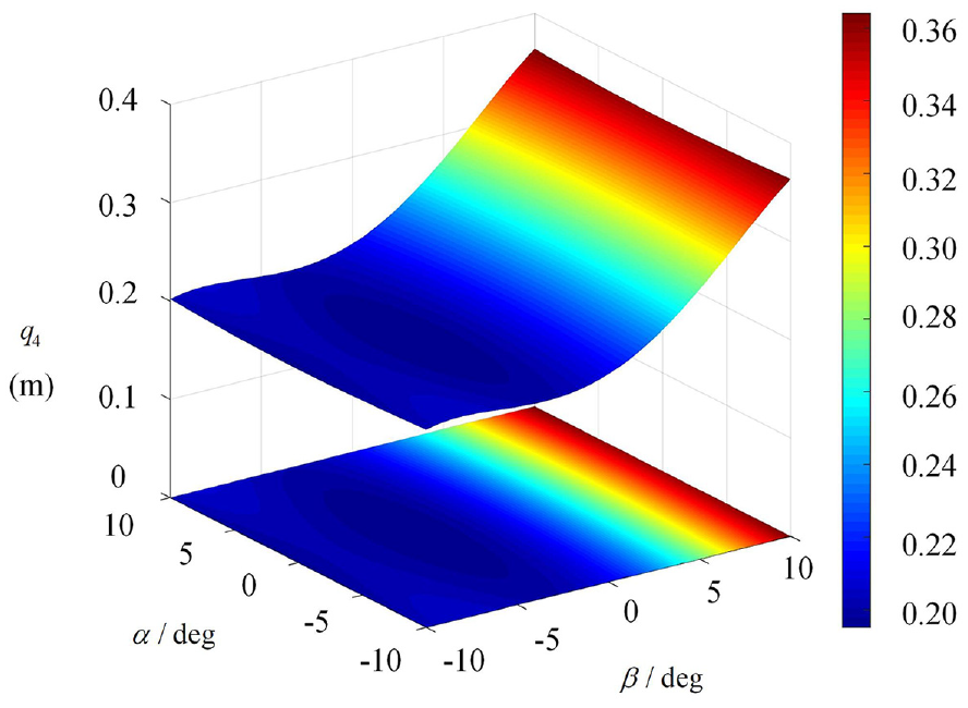
Distribution of the optimal actuating distance q4 of 2-UPR/PRPU KR-PM.
The distribution of 2-UPR/PRPU KR-PM’s minimum linear displacement stiffness performance is indicated in Figure 11. The graphic shows how the performance of minimum linear displacement stiffness varies slightly depending on the MP’s orientation. With regard to the angle, the stiffness performance is symmetrical, which is compatible with the structural features of 2-UPR/PRPU KR-PM. Additionally, the PRPU limb are arranged in the positive direction of the x-axis, so the positive value of the minimum linear displacement stiffness performance is greater than the negative direction. It is clear that 2-UPR/PRPU KR-PM performs better in terms of minimum linear displacement stiffness in the ranges of
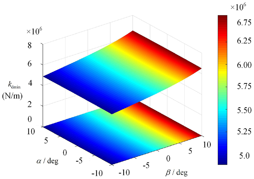
Distribution of the minimum linear displacement stiffness performance of 2-UPR/PRPU KR-PM.
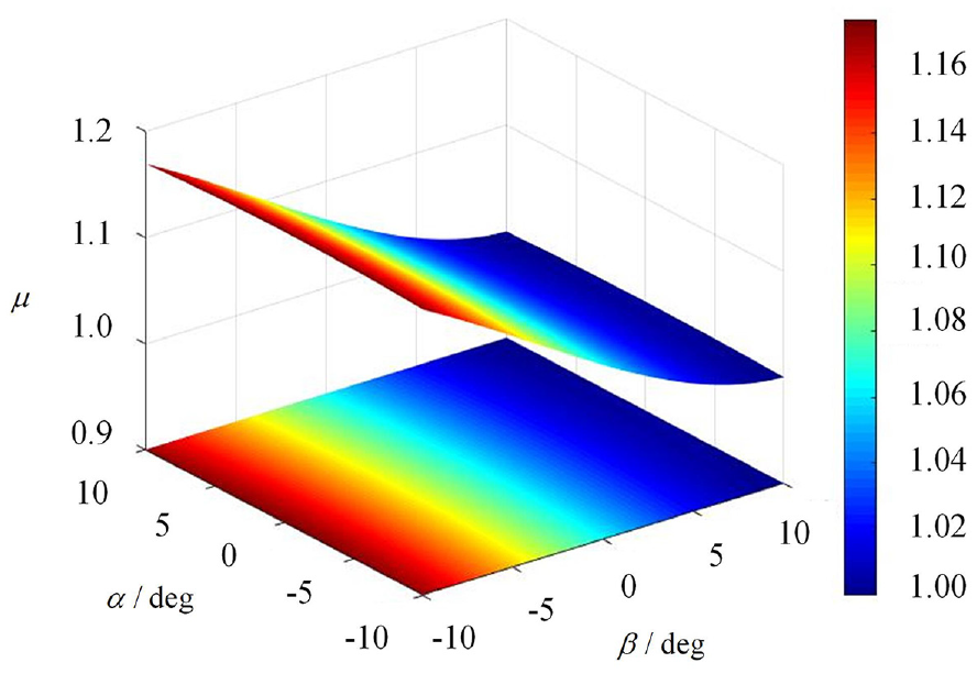
In order to show the superiority of 2-UPR/PRPU KR-PM’s stiffness performance, the ratio distribution of the minimum linear displacement stiffness performance of 2-UPR/PRPU KR-PM compared with 2-UPR/RPU PM is indicated in Figure 12. The result shows that the ratio
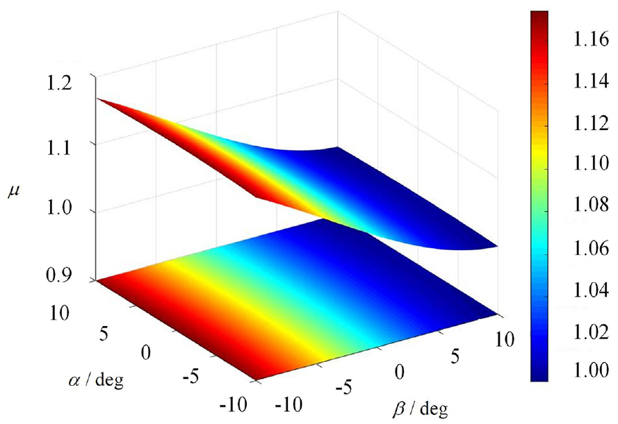
Comparison of the stiffness performance of 2-UPR/PRPU KR-PM and 2-UPR/RPU PM.
Example 2: 2-PUPR/PRPU KR-PM
Modeling of elastostatic stiffness
Structure description
To further validate the proposed approach, a 2-PUPR/PRPU KR-PM is chosen as another example. This KR-PM is designed according to non-redundant 2-UPR/RPU PM based on Lie group theory as indicated in Figure 13. 36 The 2-PUPR/PRPU KR-PM has three kinematically redundant limbs. These limbs take two P joints as the actuators to update the MP’s position and orientation.
Schematic diagram of 2-PUPR/PRPU KR-PM.
The fixed and moving coordinate frame were set the same as 2-UPR/PRPU KR-PM. Moreover, the 2-PUPR/PRPU KR-PM’s dimension parameters are defined as: OA1 = q5, OA2 = q6, OA3 = q4, oB1 = oB2 = oB3 = la.
Inverse kinematics
The inverse position solution of 2-PUPR/PRPU KR-PM is derived as
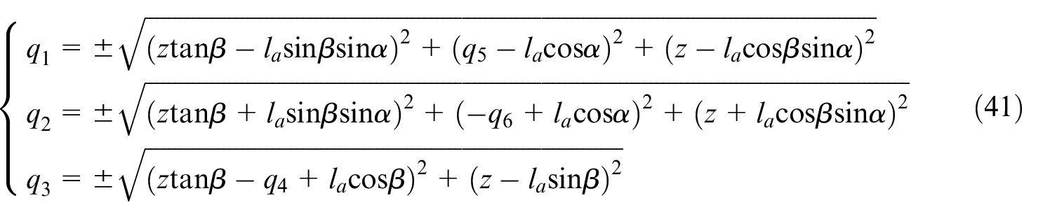
Through equation (41), the input variables qi (i = 1,2,…,6) of three limbs are not unique given the output parameters (
PUPR limb’s stiffness matrix and overall stiffness matrix
Similarly, the PUPR limb’s constraint wrench system is deduced based on the screw theory as
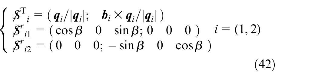
Therefore, the overall stiffness matrix of 2-PUPR/PRPU KR-PM can be expressed as

Stiffness performance analysis
The stiffness performance distribution of 2-PUPR/PRPU KR-PM is obtained as shown in Figure 14. The graphic shows how the stiffness performance varies slightly depending on the MP’s orientation. The minimum linear displacement stiffness performance is symmetrical about the angle
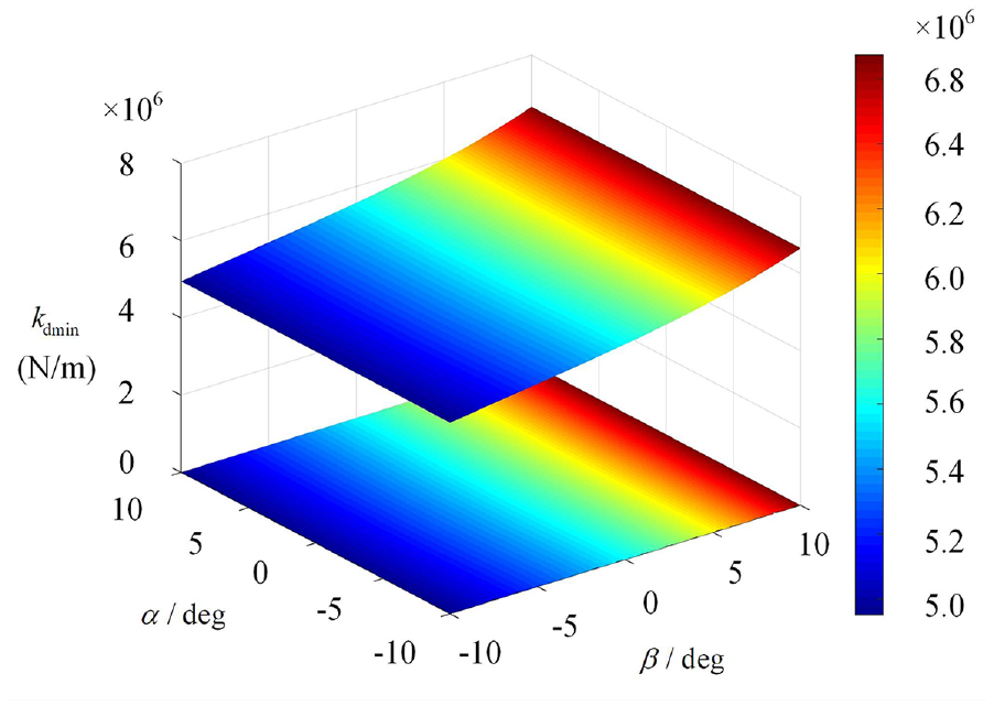
Distribution of the minimum linear displacement stiffness performance of 2-PUPR/PRPU KR-PM.
Figure 15 shows the distribution of the optimal actuating distances of 2-PUPR/PRPU KR-PM. It can be seen from the figure that the optimal actuating distance q4 varies greatly within the orientation space, while the optimal actuating distances q5 and q6 vary slightly within the orientation space. The findings demonstrate that the actuating distance q4 has an impact on the minimum linear displacement stiffness performance, while the minimum linear displacement stiffness performance is not sensitive to the actuating distances q5 and q6. The main reason is that there is only one limb on the side of PRPU limb and the stiffness performance along this direction that is relatively weak, which can be significantly improved by adjusting q4. However, the stiffness performance of the other two limbs is relatively strong, which could not be significantly improved by adjusting the actuating distances q5 and q6.
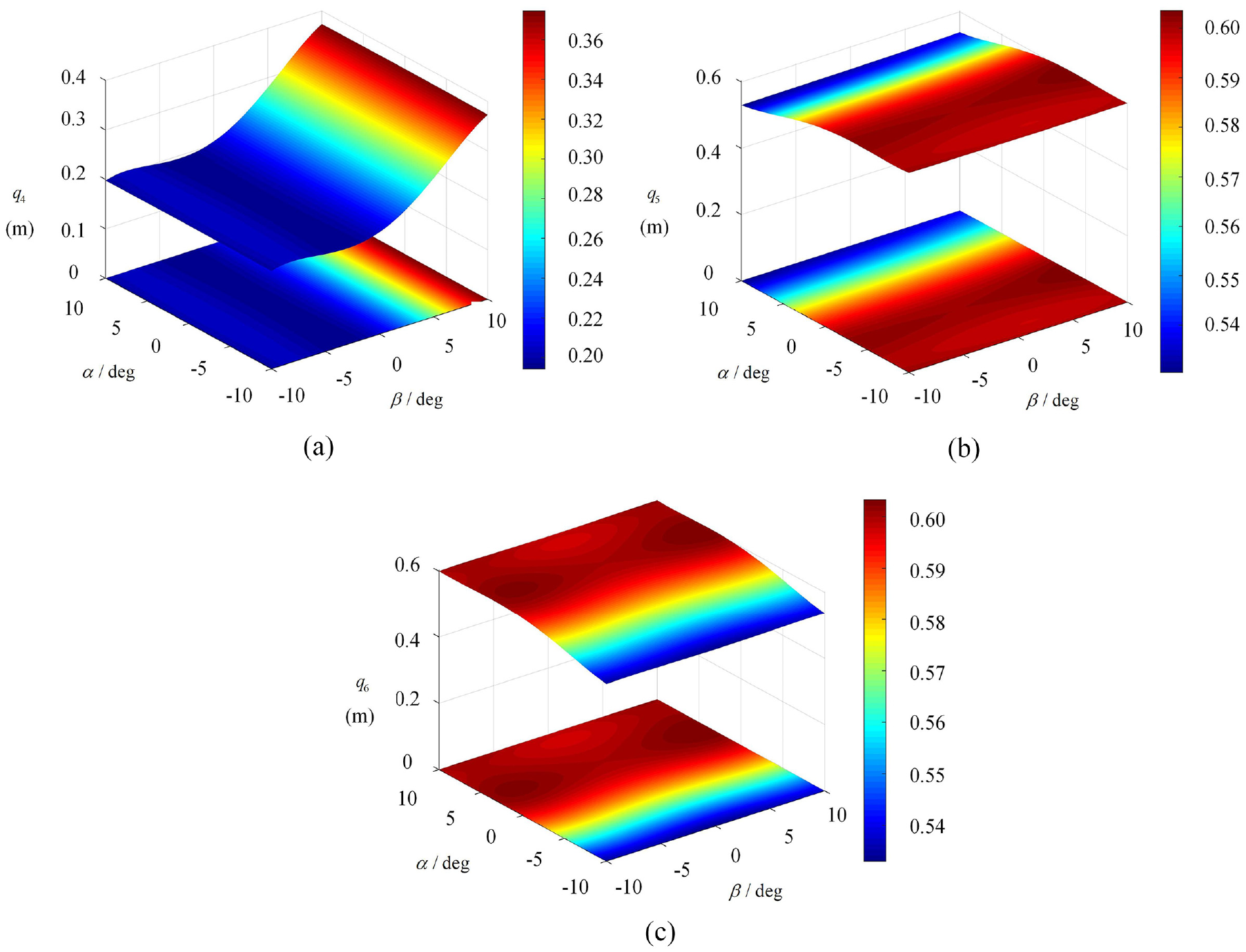
Distribution of the optimal actuating distances of 2-PUPR/PRPU KR-PM: (a) q4, (b) q5, and (c) q6.
Figure 16 shows the distribution of the ratio of the minimum linear displacement stiffness performance of 2-PUPR/PRPU KR-PM compared with 2-UPR/RPU PM. The result shows that 2-PUPR/PRPU KR-PM’s minimum linear displacement stiffness performance is superior to 2-UPR/RPU PM in the current orientation space. Compared with 2-UPR/RPU PM, the stiffness performance of 2-PUPR/PRPU KR-PM is improved by 18% at the highest.
Comparison of the stiffness performance of 2-PUPR/PRPU KR-PM and 2-UPR/RPU PM.
Conclusions
This work proposes an analytical elastostatic stiffness modeling approach based on the screw theory and the second theorem of Castigliano for KR-PMs. This approach can be employed during the design stage since it has clear modeling methodology, physical meaning and straightforward calculations. The 2-UPR/PRPU and 2-PUPR/PRPU KR-PMs are used as two examples to validate the proposed approach. When the theoretical model is compared to the FEA model, the relative error is under 1.55%. The PM’s stiffness performance is assessed by using the minimum linear displacement stiffness performance index, which is based on the theoretical model. By integrating PSO with polynomial fitting technology, an analytical mapping model of the response surface between the optimal actuating distances and the MP’s given position and orientation is established in order to quickly find the optimal actuating distances of stiffness. It is demonstrated that 2-UPR/PRPU and 2-PUPR/PRPU KR-PMs can significantly enhance the stiffness performance when compared to the 2-UPR/RPU PM’s stiffness performance.
Footnotes
Appendix
Declaration of conflicting interests
The author(s) declared no potential conflicts of interest with respect to the research, authorship, and/or publication of this article.
Funding
The author(s) disclosed receipt of the following financial support for the research, authorship, and/or publication of this article: This work is supported by the Natural Science Foundation of China (Grant no. 52275036).