
Abstract
Development of humanoids with human like range of motion for spine and torso is of great research interest. Present article covers the construction of the humanoid spine and ribs by considering spine as a hyper redundant mechanism with ribs attached in the thoracic region. To demonstrate the joints and motion characteristics, a thorough discussion of the biomechanical aspects of the spine is provided. A three-segment hyper redundant mechanism is utilised to imitate the human mimetic spine. The study considers flexion-extension and lateral bending motions of the spine. In the proposed formulation, a piecewise constant curvature approximation could simulate spine motion during flexion-extension movement. A simplified configuration with each section of spine controlled by two cables for flexion-extension and two cables for lateral bending is adopted. Additionally, a three dimensional CAD model of proposed system is developed and simulated using ADAMS. The constant curvature model and ADAMS simulation results closely match the human range of motion.
Introduction
The human body inspires a subtype of biomimetic robots called humanoids in their design. Humanoid robots are valuable research platforms for biological research and application-focused engineering and biomedical research. Humanoid robots such as Asimo, 1 Wabian, 2 and HRP 3 have been introduced in recent decades. The most recent development in this field is the creation of a humanoid with musculoskeletal systems. A series of musculoskeletal robots, including Kenta, 4 Kotaro, 5 Kojiro, 6 Kenzoh, 7 Kenshiro, 8 and Kengoro, 9 are being designed and developed. Similarities between these anatomically precise humanoids and humans in terms of body proportions, muscle organisation and joint functionality serve as the design guiding principles. 8 Nakanishi et al. 7 compared the designs of Kenta, Kotaro, Kojiro and Kenzoh in great detail. Asano et al. 8 exhaustively describe the design principles behind Kenshiro and Kengoro. Initial humanoid robots such as HRP had 30 Degrees of freedom (DoF), while Kenshiro and Kengoro have 64 and 114 DoF, respectively. 8 The increase in DoF in Kengoro is primarily due to the presence of multiple spine joints.
As end effectors, the upper and lower extremities of the human body receive the most attention from researchers. Thus, a variety of robotic hands 10 and legs 11 exist, but there are very few models of the biomimetic spine and ribs model. The human spine is a delicate and complicated part of the human skeleton made up of 24 movable vertebrae. It must provide both body rigidity and flexibility, which are contradictory requirements. Too many degrees of freedom make it difficult to replicate it mechanically.
Using the LifeMOD Biomechanics modeller,12,13 present a detailed 3D model of the spine. The spine was divided into individual components and linked together with muscles, ligaments and vertebral discs. However, this model was incapable of simulating the costovertebral joints and incorporating rib movements. Similarly, Beaucage-Gauvreau et al. 14 and Favier et al. 15 describes a multibody spine model with vertebrae and musculo-tendon actuators developed in OpenSim software. Too many musculo-tendon actuation systems make it difficult to develop a complete physical spine system with all of its muscles using this biomechanics model.
The entire spinal column is not recreated in all humanoid designs; rather, it has been condensed to a few joints that help to achieve the necessary range of motion, as in the case of Kojiro 6 and Kotaro, 5 which have four and eight vertebrae, respectively. Using the concept of planar muscles for actuation, the musculoskeletal robot Kengoro 8 comes the closest to mimicking the human spine. Although it closely resembles the human system, the control system is extremely intricate. Both approaches have disadvantages that must be addressed simultaneously in order to create a biomimetic design for a humanoid vertebral column that is both simpler and more relatable. Keeping this in mind, this paper discusses a novel way to approach the development of the human mimetic spine using a hyper-redundant mechanism. The term ‘hyper-redundant’ refers to robotic manipulators and mobile robots with an extremely large and potentially infinite, number of actuatable degrees of freedom. 16 These robots resemble snakes, elephant trunks and tentacles morphologically.
In this study, the human spine is modelled as a hyper-redundant robotic manipulator. The model consists of three segments, each of which represents one of the three curvatures of the human spine. These segments will be actuated by a mechanism that is based on a tendon and pulley. In the thoracic area, the rib cage is also modelled with a peculiar idea of costal cartilage and costovertebral joint modelling. Direct forward kinematics and a constant curvature assumption are used to build the kinematic modelling of the model. In MSC ADAMS, the proposed model is simulated, and the simulation output is compared to human movement range and constant curvature model. The workflow and topics discussed in this paper are depicted in the flowchart in Figure 1.
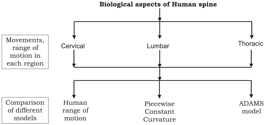
Flowchart of work.
Biological aspects
The first step in creating a biomimetic model is to comprehend the essential biological characteristics of the system. The vertebrae and intervertebral discs constitute the majority of the human vertebral column (IVDs). There are 33 vertebrae in total, which are split into 5 regions/segments 17 : 7 cervical vertebrae, 12 thoracic vertebrae, 5 lumbar vertebrae, 5 fused sacral vertebrae and 4 coccygeal vertebrae (fused). The sacrum and coccyx are joined to the hip. Figure 2(a) depicts the curvature of various spine segments. The cervical region or neck is concave posteriorly to support the head and bring it closer to the line of centre of gravity. Similarly, the lumbar area must support the entire weight of the upper body, causing it to again reach concave curvature posteriorly and migrate towards the centre in order to distribute the weight to the pelvic girdle and lower body. In order to provide room for internal organs, the thoracic area acquires convex curvature posteriorly. 17 Flexibility and stiffness are opposing requirements for the spine. Flexibility to permit motion in all directions and rigidity to support body weight, transmit loads and stabilise the torso by providing posture. 17
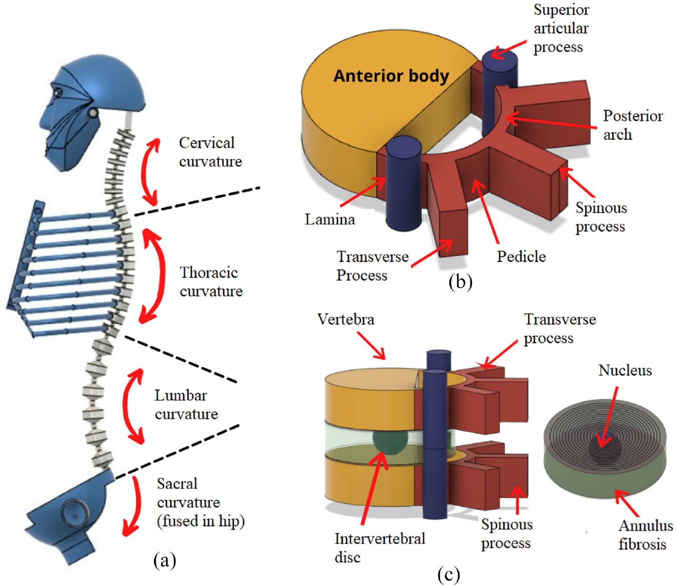
(a) Spine curvature, (b) a typical vertebra and (c) Functional Spinal Unit (FSU) and Intervertebral disc.
A typical vertebra, as depicted in Figure 2(b), consists primarily of two parts: the weight-bearing Anterior Body and the Vertebral or Neural Arch, also known as the Posterior Arch. Between the body and the arch, the spinal cord goes via the foramen. As seen in Figure 2(b), the posterior arch is comprised of two pedicles and two laminae. The extra bony structures called ‘processes’ that are attached to the arch act as anchors and lever arms for different muscles and ligaments. The transverse process connects the ribs to the spine in the thoracic area. 17
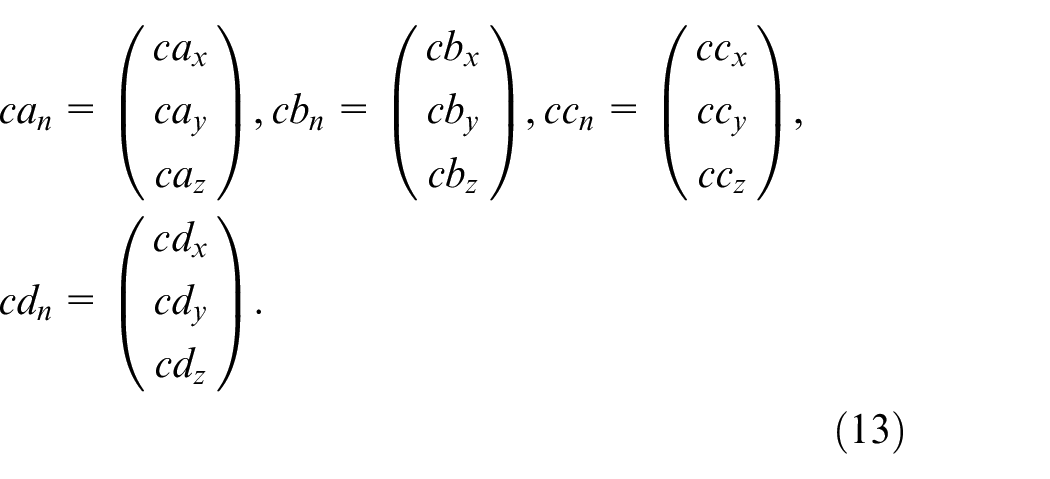
As seen in Figure 2(c), the vertebrae are joined by the intervertebral disc (IVD) located between the vertebral plateau. IVD occupies approximately one-third of the whole column height and is the primary flexible joint. It transmits movement- and body-generated loads across the entire column. It is flexible in terms of bending and twisting. 18 The disc is made up of three interconnected components: the nucleus, the annulus and the cartilaginous endplates. The nucleus pulposus, which is in the middle, is a gelatinous mass made up mostly of proteoglycans (PGs), collagen fibres, elastin fibres and chondrocyte-like cells. The peripheral portion of Annulus fibrosis (AF) is composed of concentric collagen and elastin fibres. The cartilaginous endplates are a 1 mm thick semipermeable membrane that serve as the superior and inferior limits of the IVD. It enables fluid circulation to the nucleus and protects the vertebral body from rapid changes in pressure. It restricts the Annulus and nucleus to their anatomical limits. 18
In the thoracic area, the ribs attach anteriorly to the Sternum and posteriorly to the vertebrae. The costal cartilages connect the ribs to the sternum in front, while in the rear, each thoracic rib articulates to its corresponding costovertebral joint, as depicted in Figure 3.
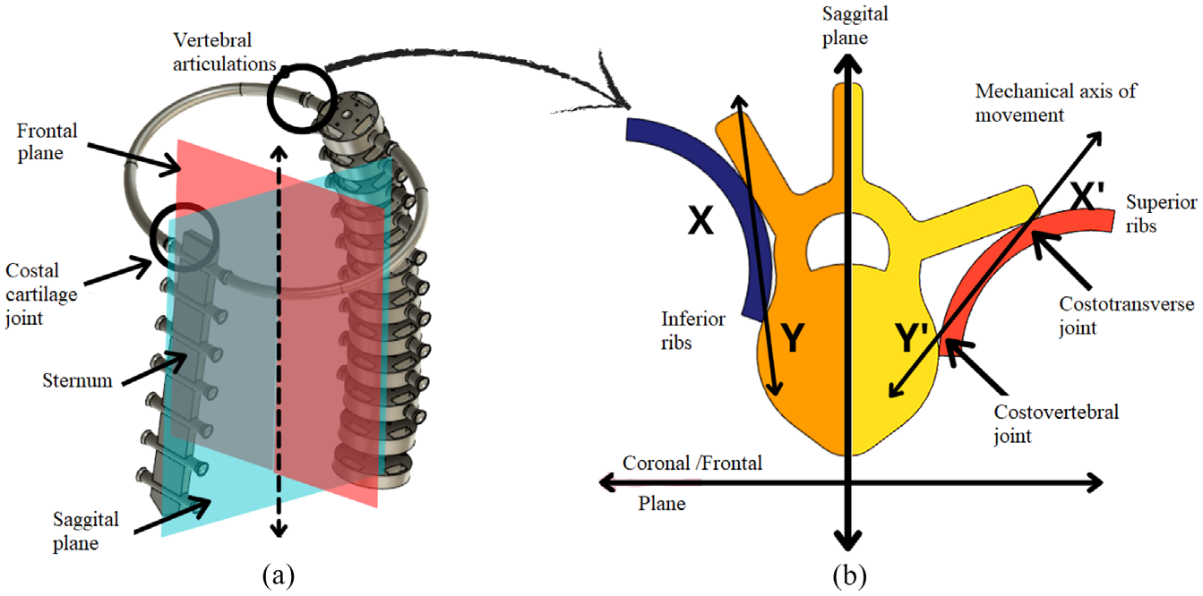
(a) Rib joints in CAD model and (b) costovertebral and costotransverse articulation and movement axis in upper and lower ribs.
As is commonly misunderstood, the ribs are not linked to the thoracic vertebra or the sternum; instead, they are attached to the sternum by costal cartilage and form an articulation at the vertebral end. These joints contribute significantly to the flexibility of the thoracic spinal column throughout the development of the humanoid configuration. The costotransverse and costovertebral joints are mechanically interconnected articulations of the ribs. The ribs move about the axis that passes through these two contact points. 17
For the upper ribs (
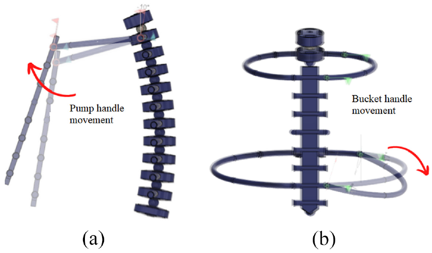
(a) Pump handle movement and (b) bucket handle movement.
Spinal movements
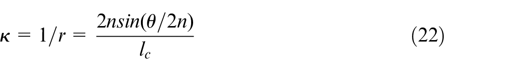
During various actions, the vertebral column provides two bending movements, flexion-extension and lateral bending, as well as one axial rotation and one translational movement, due to the compressive forces of effective body weight. In this study, only rotational degrees of freedom are taken into account, as translational DoF do not demonstrate very significant motion. 20 Due to the technical difficulties inherent in the testing of multi-segmented, flexible spinal specimens, a great deal of published material examines the Functional Spinal Segment.
The Functional Spinal Unit (FSU) or Spinal Motion Segment (SMS) is the smallest segment of the vertebral column capable of exhibiting all biomechanical characteristics of the entire spine. 20 The FSU consists of two adjacent vertebrae and the connecting IVD. The study also considers the articulation between ribs and vertebrae in the thoracic region. In general, for biomechanical testing and analysis, the lower vertebrae are assumed to be fixed and the upper vertebrae are subjected to loads and moments. 20 The behaviour of FSU is complicated and highly dependent on geometrical factors and ligament stiffness in that region. 21 Spinal stability and mobility are mutually exclusive characteristics. If the motion is left unrestricted, the load-bearing capacity and stability will decrease, whereas the range of motion will decrease as more constraints are effectively applied. The functional spinal unit is therefore a compromise between stability and mobility. It is a semi-restricted system that permits physiological motion up to certain angular limits by restricting excessive motion. 21
According to the references, IVD has a viscoelastic nature 20 ; therefore, all mechanical tests must be conducted at a slow loading rate to reduce this effect. Mechanically, the IVD exhibits biphasic, non-linear elastic behaviour. When the load exceeds a certain threshold, the resistance to change increases. As shown in Figure 5, the first zone near the neutral position is called the Neutral zone (NZ), and the second zone is called the Elastic zone (EZ). 21 The total range of motion comprises both zones. The definition of the average flexibility coefficient is the displacement in the elastic zone divided by the maximum physiological load before failure. In general, but not always, the stiffness or flexibility coefficients provided in the literature account only for the second phase, leaving the neutral phase unaccounted. 20
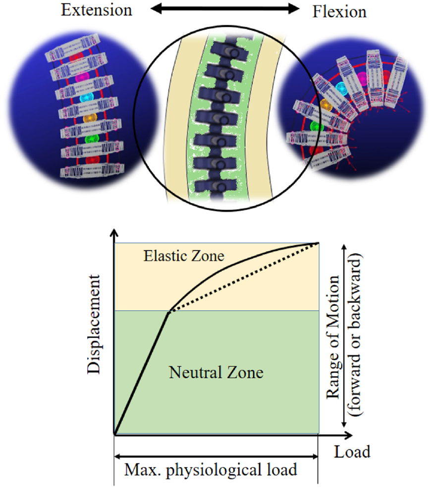
Load displacement curve of spine.
The stiffness coefficients presented in Table 1 illustrate the relative flexibility of the spine in different directions. It should be emphasised once more that the spine’s behaviour is quite complex (non-linear, biphasic and viscoelastic) and that representing it with a single number may not be very accurate, but can be updated later according to the complexity of the behaviour. The movement of the spine does not occur at a single point, but rather in segments. The SMS is considered a joint complex that permits all three rotations as needed.
Moment stiffness constant of representative functional unit. 20
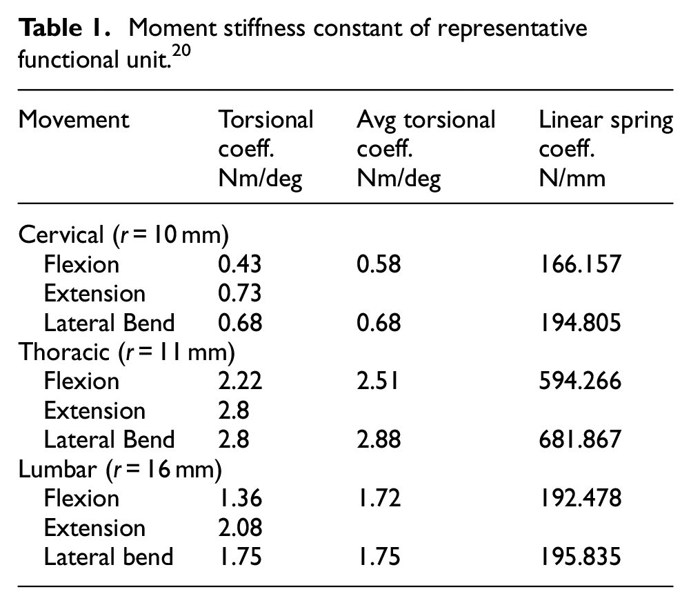
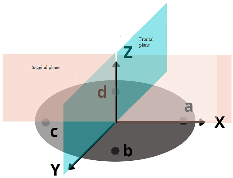
The rotational spring stiffness was then transformed into four linear springs in the sagittal and frontal planes by equating the torques provided by both at the nucleus’ centre. These springs correspond to movements of flexion-extension and lateral bending.


where
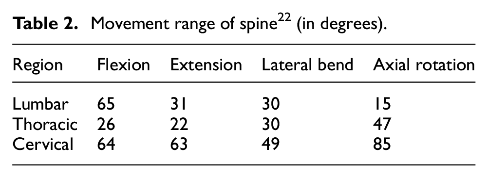
As the shape of vertebrae, IVD and ligament attachments vary between regions, so does the range of motion. The range of motion in the individual SMS may be small, but the cumulative effect is significant and provides the vertebral column with very high degrees of flexibility and motion ranges. Flexion-extension occurs in the sagittal plane, whereas lateral bending occurs in the frontal plane. The range of movements in various regions is shown in Table 2.
Movement range of spine 22 (in degrees).
Mechanical aspects
To design a bio-inspired spine model, each of the aforementioned biological factors must be considered. The primary concern is meeting all of the requirements for realistic motions and controls. This realistic motion requires a large number of degrees of freedom in the body’s linkage and complex control systems to be realised. In order to simplify the control, we must simplify the complex model without compromising the realism of the movements.
Only four vertebrae are used in the Kojiro robot,6,23 which are controlled by a tendon-based muscle arrangement and spherical angle sensors. In contrast, the Kenshiro8,24 and Kengoro8,9 robots attempt to simulate the entire musculoskeletal system surrounding the vertebral column. This necessitated the use of a planar muscle system and the control of individual muscles via antagonistic relationships, which complicated the control system requirements. The primary design objective of this study was to propose a novel spine model with minimal control requirements and movements that are nearly realistic. Here, only the lumbar, thoracic and cervical regions of the human spine are taken into consideration for design. Due to its fusion with the hip, the Sacral region can be assumed to provide orientation at the base of the spine despite its considerable mobility. The primary objectives of the model were to allow as many degrees of freedom as possible in all three regions, to demonstrate the anatomy of physical vertebrae and discs and to achieve a movement range comparable to that of the human body.
In a simplified mechanical approximation, the front body of a typical vertebra can be considered as the primary sector of a cylinder with a width that is greater than its height, while the posterior arch can be assumed to be a ring-shaped cylinder. The movement of the spine is made up of a series of vertebral movements connected by joints that depend on each other. This makes it hard or impossible to isolate and study movement at just one joint. These motions are begun by a collection of muscles that span the entire region of the neck, belly and back. 17
First approximation of the FSU, consisting of two vertebrae and a nucleus, can be represented as a ball inserted between two discs. The elasticity exhibited by the fibrous portion of the IVD can be represented by a spring-damper combination in four directions, each of which represents two bends. This analogy of the spring damper system is drawn from references,25,26 where IVD is represented by a non-linear spring damper system dependent on upper vertebral displacement. Although in our situation we are utilising a linear spring damper system to simplify the model for use in humanoid form, this is done to make it more practical. This form of joint eliminates spring compression along a single axis while allowing movement along all three axes.
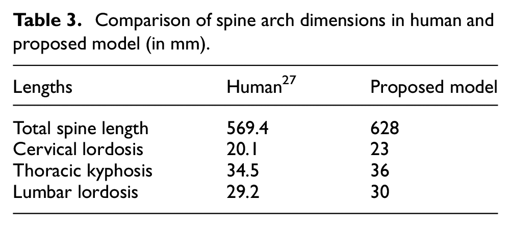
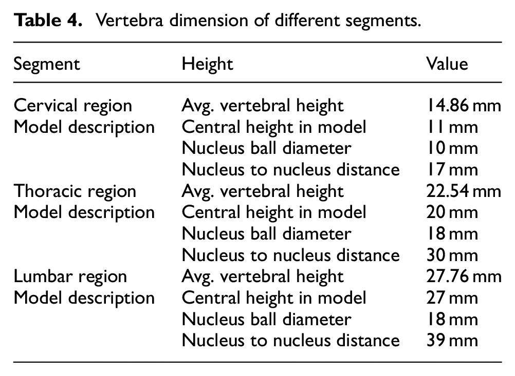
Despite the fact that it has been proven that the vertebral column is separated into three distinct segments with independent motions, the basic size and curvature of these three segments are not independent. In order to achieve anatomical likeness, the spine’s curvature and total length are made comparable to the average human size. The subtended angles that reflect the curvatures are known biologically as Cervical lordosis, Thoracic kyphosis and Lumbar lordosis. The comparison of anatomical dimensions and model dimensions is shown in Tables 3 and 4. The dimensions of the model are depicted in Figure 6.
Comparison of spine arch dimensions in human and proposed model (in mm).
Vertebra dimension of different segments.
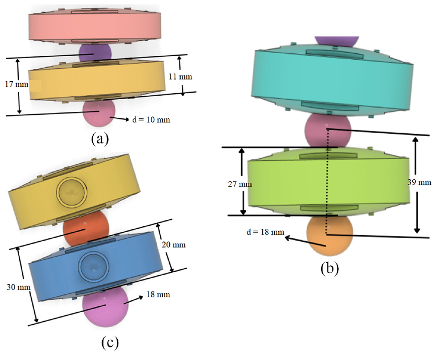
Model dimensions for different segments: (a) cervial vertebra, (b) lumbar vertebra and (c) thoracic vertebra.
The size of each vertebra is not the same all the way through. The topmost cervical vertebra is the smallest, and the diameter gradually increases till the end. 20 Due to the need for a long moment arm to generate the necessary movement, the diameter of the model does not closely resemble the actual diameter of a human body. In the human vertebral column, the increase in diameter from the first to the final vertebra is maintained. For the thoracic area, the dimensions of the rib cage are referred from Dansereau and Stokes. 28
Actuation system
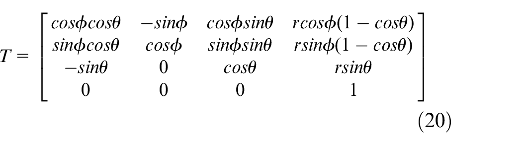
As each FSU must now control three DoF, planning the actuation of the entire system is a difficulty. A single FSU is a relatively simple ball-and-socket joint with 3independent rotatory motion, but the entire vertebral column consists of 24 movable vertebrae (5 Lumbar, 7 Cervical and 12 Thoracic), resulting in 24 ball-and-socket joints with 72 independent degrees of freedom. Utilising the notion of Hyper Redundant Robotics is an efficient approach to this issue. Redundancy refers to numerous methods to execute the same activity and is typically expressed as degrees of freedom. 29 This notion is utilised extensively in the construction of Snake robots, Elephant trunk manipulators and Octopus robots, where the same objective can be attained through distinct actions.
The human spine can be viewed as a highly redundant system with each FSU serving as a module. The movement of the spine is highly regulated, as it follows a very particular path confined by numerous body parts and muscles. The entire column of vertebrae is separated into three hyper redundant segments, namely cervical, thoracic and lumbar, with each vertebra or FSU functioning as a module. Lumbar segment has 5 modules, Thoracic segment has 12 modules and cervical segment has 7 modules. Biologically, three segments exhibit independent movement ranges in all three directions, hence it is proposed that each segment can be constructed with an independent actuation system. Later, the three pieces can be joined into a complete model of the vertebral column.
According to Afolayan et al., 29 biologically inspired hyper-redundant joints are constructed utilising rigid multi-axis joints attached in sequence, the majority of which consist of universal joints, parallel mechanisms, revolute joints and angle swivel joints with universal joints. Common actuation mechanisms for continuum robots are pneumatic tubes, flexible rods and tendon-based systems. 30 It is proposed to utilise a system based on a tendon pulley since it requires less space and is effective in transmission. This will under actuate flexion-extension and lateral bending in the sagittal and frontal planes, respectively. Although this will compromise the spine’s z-axis rotation. Therefore, the system will only exhibit 2 DoF at each ball joint, for a total of 48 DoF in the spine.
The suggested model’s conceptual design can be summed up as the construction of three segments of hyper-redundant robotic manipulator independently actuated by tendon-pulley based system. The joint in each vertebra is a ball-and-socket joint with elastic components representing the nucleus and fibrous annulus of the IVD positioned between each functional unit. The system will be capable of demonstrating spinal flexion-extension and lateral bending. Due to the presence of tendon-based actuation, axial rotation will be limited.
Kinematic and kinetic formulation
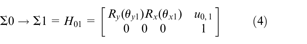
Direct forward kinematic
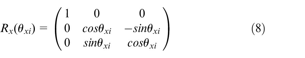
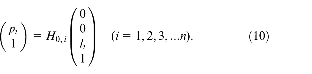
Consider that there are
Position naming on the vertebral disc.
Kinematic structure.
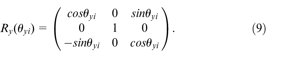
where
where
We obtain the position vector and unit vector of the
Four spring attachment position vectors at the base plate are determined as follows:
The position vectors of four spring attachments at the
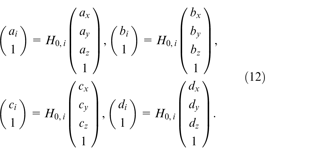
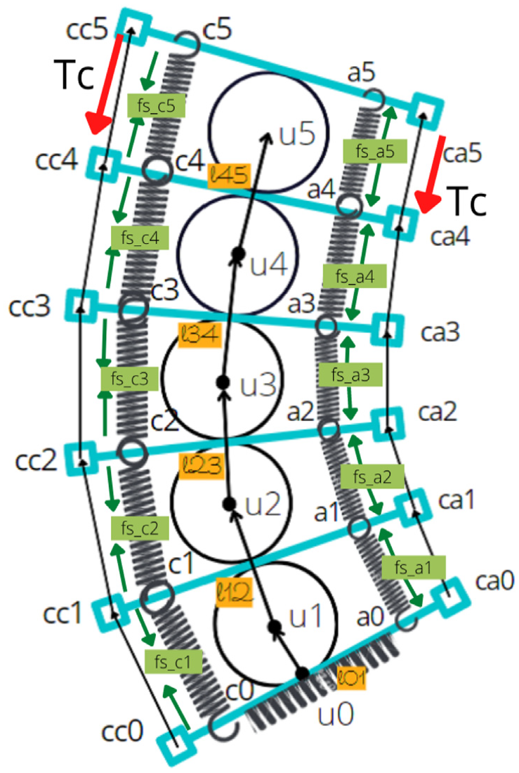
The majority of cable force will act on the final vertebra of the portion where it is fastened. For the rest of the vertebral disc, the only force attributable to the cable will be friction on the pulley, which is readily ignorable. Position of cable attachment for topmost vertebra relative to final universal joint (
Kinetic formulation – force and moment balance
In the model, there are two components that apply force: the cable that is being tugged and the spring that connects two discs. The expression for spring force for springs linking the


Here,
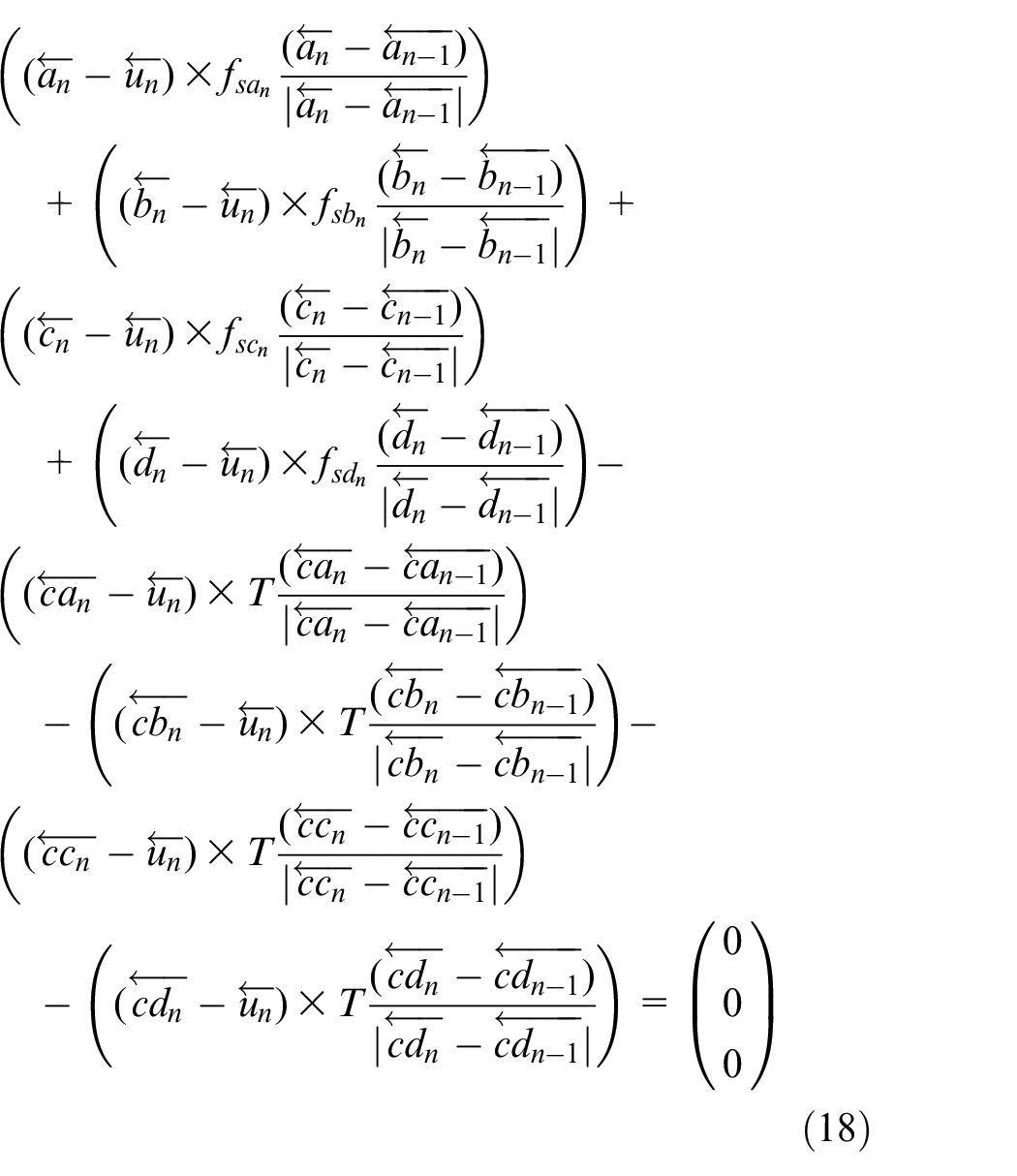
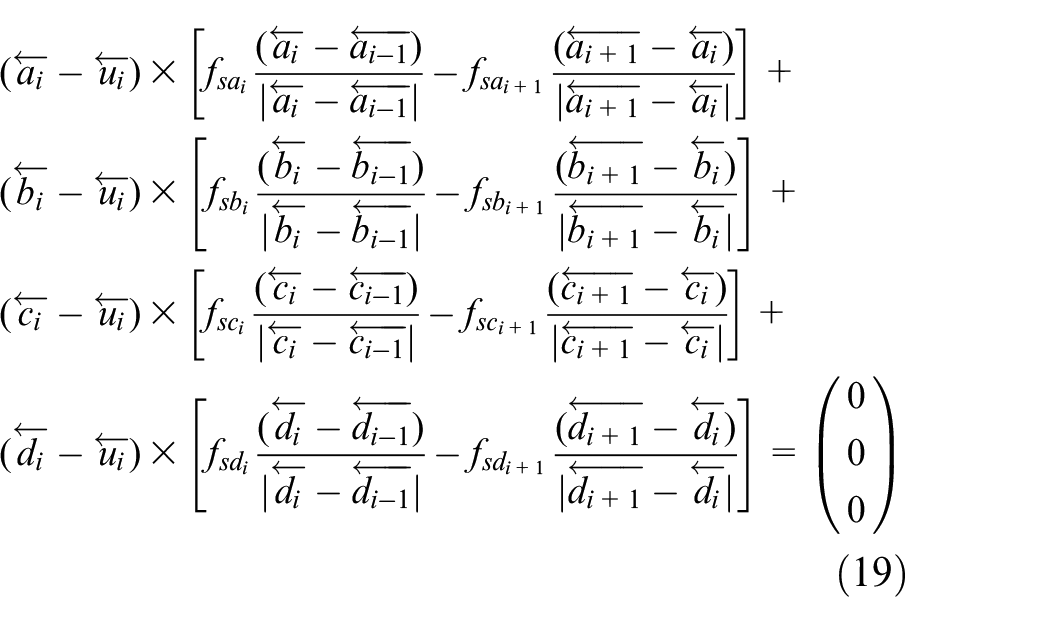
On other vertebra, cable tension is irrelevant because the pulley just guides it over. The springs connecting the subsequent and final vertebrae will generate opposing forces. Equation (19) expresses the moment balance in equilibrium state over other vertebrae.
In the preceding expression, the angle of rotation at each ball joint is a single variable. If we examine only two rotations, that is, lateral bending and flexion-extension, there will be
Piecewise constant curvature
Assumptions
Two major assumptions for modelling kinematics of spine through constant curvature are:
It is only possible to model planar movements, that is, flexion-extension of spine segments. Lateral bending occurs out of plane, hence it cannot be modelled using this method.
At any point of deflection, the arc generated by a section of the spine is either a portion of a circular arc or maintains a constant curvature.
Constant curvature is a desirable characteristic
30
for continuum robots. It facilitates the simplicity of the system’s kinematic modelling. Constant curvature robots consist of a finite number of curved linkages that can be characterised by arc parameters and transformed into analytic frame transformation.
30
This approach is also useful for differential kinematics and real-time control analysis. The piecewise constant curvature permits the decomposition of kinematics into two mappings.
30
First mapping from the space of actuators to the space of configurations. The second transition is from configuration space to task space. Actuator space variable (
The mapping between configuration space and task space is independent, that is, identical for all continuum robots. Because every robot will have a unique actuation system, the mapping between actuator space and configuration space is robot-specific. A discussion of the specific mapping of a common actuator system is presented in Webster and Jones, 30 which was also used to establish this formulation.
Independent mapping is nothing more than a homogeneous transformation matrix parameterised by arc parameters (
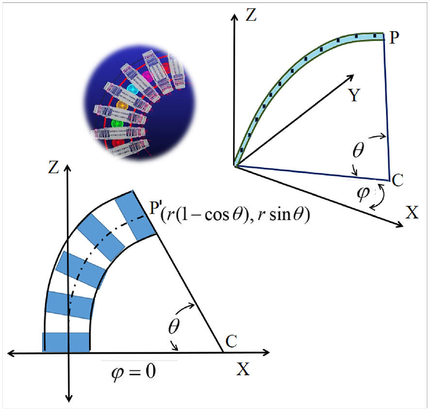
Arc space parameter.
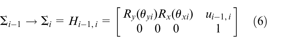
The transformation matrix can be written as:
where
In Webster and Jones, 30 it is fully explained that the same transformation matrix may be obtained using other established approaches such as DH (Denavit-Hartenberg) parameters or Fernet Serret frames. This is the simplest technique to do the desired modification. This expression is valid for any continuum robot whose base coordinate axis coincides with the X axis. In the case of the human spine, the base of all three segments are rotated about the Y axis by a certain angle – for example, the lumbar region is turned by 16 degrees – so when we use it in the model, we need to include one more transformation of rotation about the +Y axis.
Finding the arc parameters
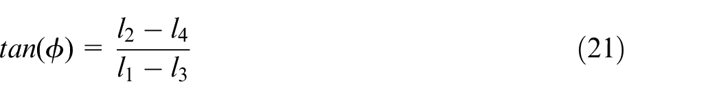
Now, using the
where
From this formulation, the only way to derive arc parameters is to know the instantaneous cable lengths between two vertebrae. Combining the robot’s independent and particular components, there are just four variables in this method, which are the cable lengths between two vertebrae. The initial total cable length and winching speeds on all four sides can be used to calculate the instantaneous cable length. The primary limitation of this formulation is that the movement must occur in a single plane. In the case of the spine, flexion-extension occurs solely in the sagittal plane, hence this approximation stays true and may be observed during simulations. In contrast, during lateral bending, each vertebra of one segment will move in a different plane due to the spine’s curvature; therefore, this formulation does not accurately define lateral bending. The final position of the arc depends solely on the actuator space variable in this case, the cable lengths and not on the spring stiffness. The force and moment needed to move the cable will depend on how stiff the spring is, but the change in arc will stay the same as long as the cables have the same length of movement.
ADAMS simulation and results
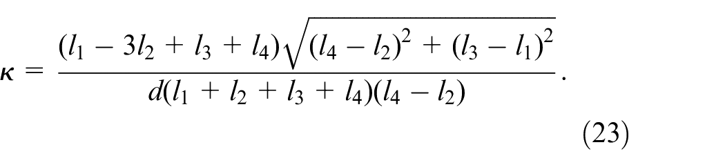
Individual portions of the vertebral column were modelled in CAD. The model was exported as an IGES File for simulation purposes. In MSC ADAMS, cable-based actuation was modelled for the modelling of our mechanism. The vertebrae are depicted as tapering discs in Figure 5. According to Section (mechanical aspects), the nucleus of IVD is represented as a sphere, whereas the fibrous component of the annulus is represented by a linear spring system. Each segment’s flexion-extension is controlled by a set of two cables, while its lateral movement is controlled by a second set of two wires. These movements are replicated independently for simulation purposes, and only two wire systems are employed each simulation. The linear spring coefficients from Table 1 are employed. Between two vertebrae, the cable is wrapped so as to form a straight line. It permits the predominant component of force to be tangential to change the shape of the curvature. Normal forces won’t make the curve change, but will instead cause the system to fail. The tension in the cable will be maintained by the guiding pulley. The cable pulley system is illustrated in Figure 10.
Cable pulley system.
In the ADAMS simulation, the wires are attached to the top vertebra and operated on the bottom vertebra of each segment. In ADAMS, the winching variable for each cable is configured as a STEP function. The simulations were conducted utilising the MSC ADAMS solver’s default parameters and the GSTIFF integrator.
Figure 11(a) and (b) depict different instances of cervical segment flexion and extension. The illustration labelled A depicts the neutral curvature of the spine, whereas the illustrations labelled B, C, D and E, F, G depict various occurrences of flexion and the extended lumbar segment, respectively. Figure 11(c) depicts the arc parameters derived from independent mapping of the cervical section for the identical flexion or extension movements using a constant curvature technique. As shown in Figure 11(a) and (b), the cervical segment can bend in both directions up to the mechanical limits of the suggested model.
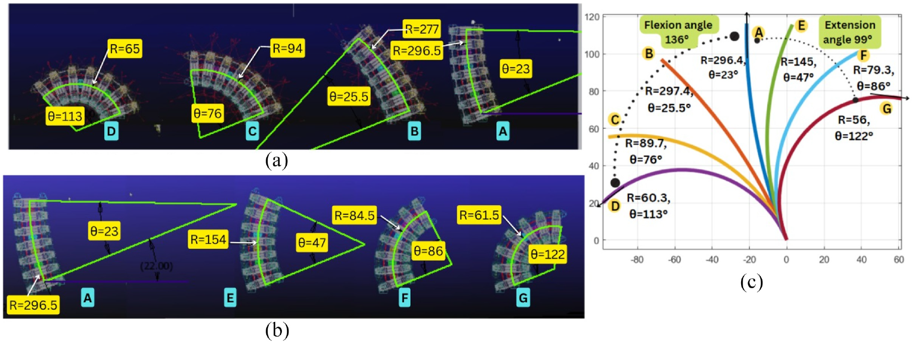
ADAMS simulation flexion-extension movement range and Constant curvature model for Cervical segment: (a) ADAMS flexion simulation – Arc parameters at different instants, (b) ADAMS extension simulation – Arc parameters at different instants and (c) Arc parameter from independent mapping of constant curvature.
Analysing the proposed model at various times during flexion and extension reveals that the arc generated by the segment’s central line is part of a circle whose centre lies on the same line. Moreover, it is obvious that the arc parameters obtained by analysing the ADAMS model at different instances of the simulation are in close agreement with the arc parameters obtained by the independent mapping of the segment for the same movement using a constant curvature approach. Since flexion-extension movement occurs in the same plane and segment curvature is always part of a circular arc, the concept of modelling the system using a constant curvature approach is validated.
Figure 12(a) and (b) depict different instances of lumbar segment flexion and extension. As mentioned in the cervical segment, the illustration labelled A depicts the neutral curvature of the spine, whereas the illustrations labelled B, C, D and E, F, G depict various occurrences of flexion and the extended lumbar segment, respectively. Figure 12(c) depicts the arc parameters derived from independent mapping of the lumbar section for the identical flexion or extension movements using a constant curvature technique.
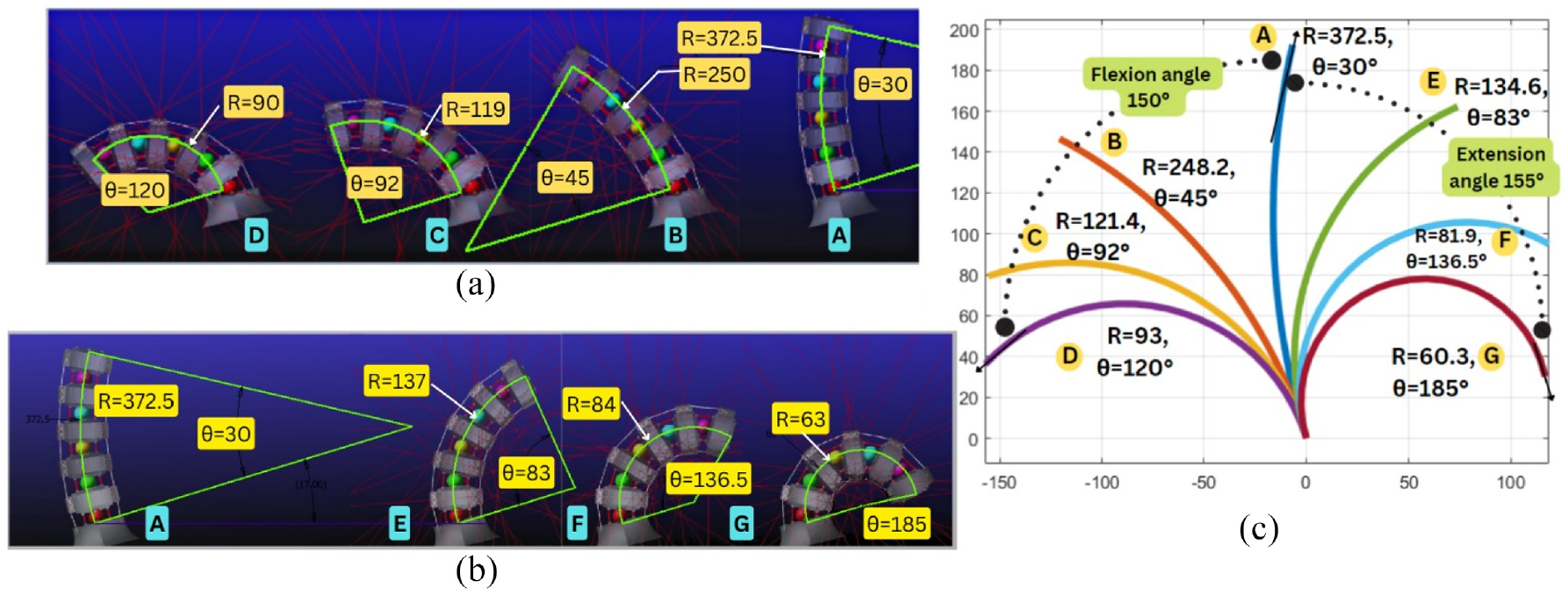
ADAMS simulation flexion-extension movement range and Constant curvature model for Lumbar segment: (a) ADAMS flexion simulation – Arc parameters at different instants, (b) ADAMS extension simulation – Arc parameters at different instants and (c) Arc parameter from independent mapping of constant curvature.
Based on Figure 12, similar conclusions can be derived for the lumbar segment as for the cervical segment. Lumbar segment can also bend in such a way that the central arc is always a part of a circle, and the arc parameters obtained from ADAMS simulation results are extremely comparable to those obtained from lumbar segment constant curvature approximation.
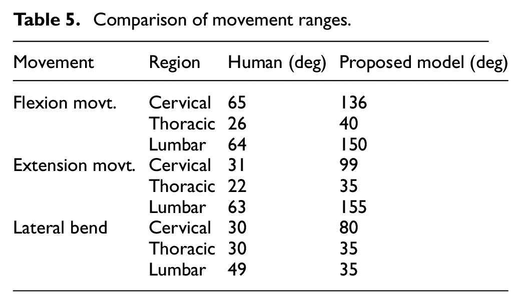
These movements of the suggested model exceed the spectrum of human mobility. Human movement is constrained by several aspects, such as the presence of different organs and muscle lengths, but we have not accounted for these factors in our model, therefore it surpasses the range of motion visible to humans. Although these limits can be implemented and optimised at a later stage.
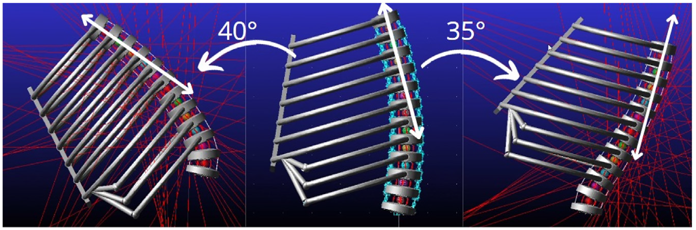
For the thoracic area, it was noticed in Figure 13 that, out of 12 vertebrae, ribs are joined to the top 10 vertebrae, causing a difference in curvature between these portions. The top vertebrae where the ribs are attached are bending with a common curvature, however the second bottom vertebra of the thoracic region has a little shift in curvature, which may be owing to the ribs’ additional moment at this point. The thoracic region’s range of motion closely resembles the human range of motion. During motion, the costovertebral and costal cartilage joints of the ribs exhibit a combination of ‘pump handle’ and ‘bucket handle’ movement. Therefore, the proposed design of costovertebral and costal-cartilage joints is suitable for usage in humanoid models after the relevant parameters have been optimised in accordance with the requirements.
ADAMS simulation flexion-extension movement range for thoracic segment.
During lateral bending, as depicted in Figure 14, the movement resembles that of the human body. All the vertebrae bend on distinct planes, preventing them from exhibiting the correct curvature of movement during flexion and extension, and preventing them from being formulated using the piecewise curvature approach. As part of future investigation, a mathematical model for lateral bending can be formulated. A summary of comparison between human range of motion and the proposed model for various segments is mentioned in Table 5.
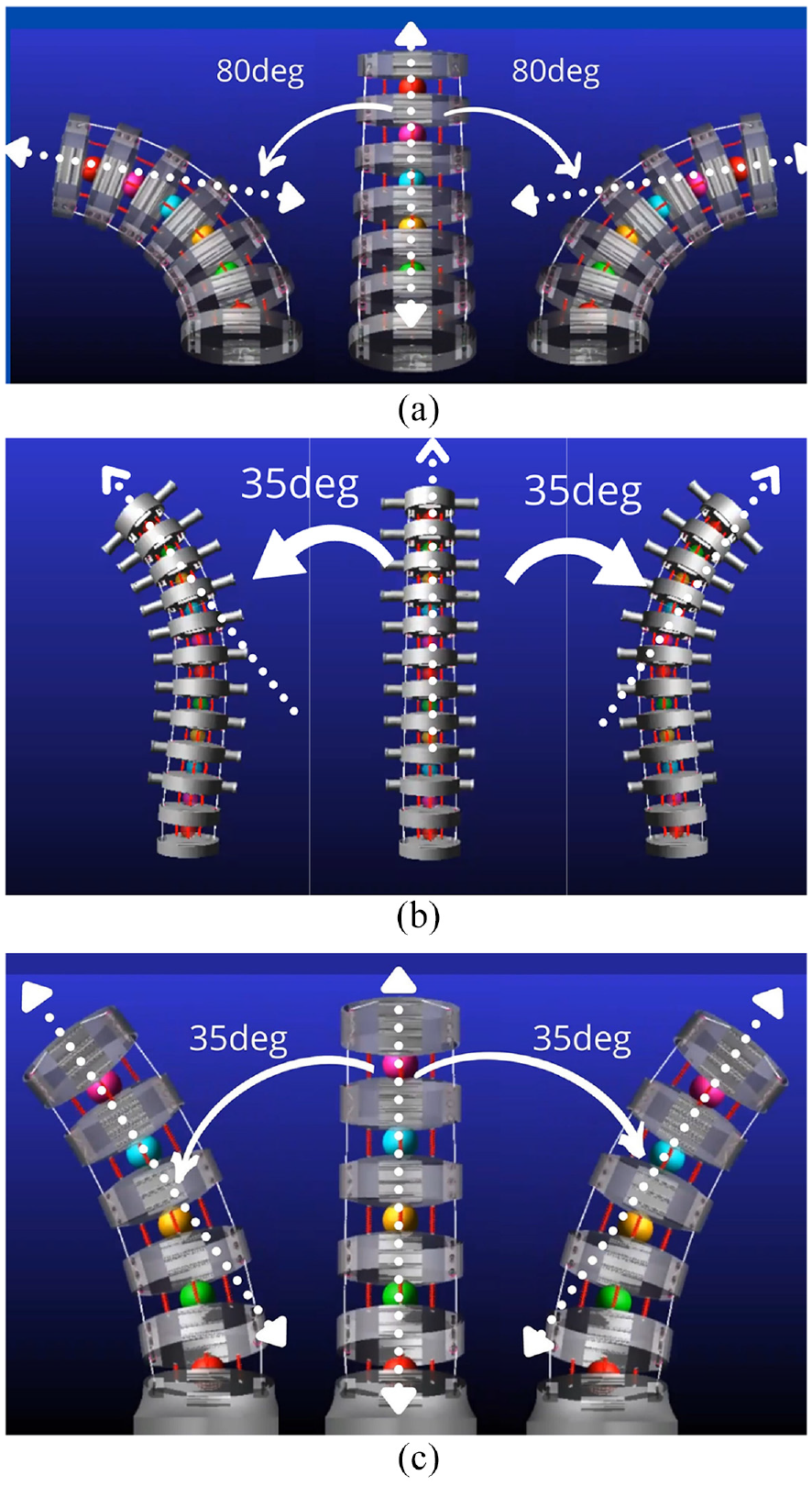
Movement range of proposed model (a) cervical lateral bending, (b) thoracic lateral bending and (c) lumbar lateral bending.
Comparison of movement ranges.
Conclusion
In this paper, we introduce a human mimetic spine model with a hyper-redundant mechanism that allows humanoid robots to mimic human motion. In order to further illustrate the many joints, motions and other considerations, a detailed discussion of the biological elements of the human spine has been added. On the basis of the biological characteristics of the human spine and ribs, a 3D CAD model was created and is used to simulate movement using the ADAMS platform.
In light of the findings, it can be inferred that the suggested three-segmented hyper redundant mechanism can be used to mimic human mimetic spine, since the proposed system effectively matches the range of motion of individual human spine. Moreover, it is obvious that flexion-extension motion in the mechanism may be theoretically modelled using a piecewise constant curvature technique, as the independent mapping of constant curvature is in good agreement with the system’s ADAMS simulation results. It simplifies the control system because each segment of the spine is controlled by two cables for flexion-extension and two cables for lateral bending. However, constructing the mathematical model for specific mapping from the actuation system to configuration space requires a comprehensive investigation. The model’s kinematic and kinetic formulations have been established by direct forward kinematic formulation. The application of a piecewise constant curvature approximation in the suggested formulation could approximate spine motion in flexion-extension movement.
The models of three segments; the cervical, thoracic and lumbar regions; described in this study may be valuable for researchers to comprehend the motions connected with the human spine and to apply the proposed modelling approach to future assembly designed to serve specific humanoid applications.
Space robotics, simulated human space flights, exoskeleton design for medical purposes, disaster management robots, etc., all highlight the importance of investigating the modelling and simulation of mimicking the human spine and torso. The present research lays a groundwork that can be developed further in several ways, such as optimising for specific motion ranges, designing with manufacturing in consideration, etc. There are still a number of unanswered concerns, including how to build a mathematical model for the lateral bending and axial rotation of individual spine segments, how to integrate the three separate segments into a whole, and how to analyse the whole. We will be directing our future efforts towards finding solutions to these problems and gaining experimental proof of our idea.
Footnotes
Authors’ contributions
All authors have participated in the conception, design, drafting, revision and approval of the submitted manuscript.
Declaration of conflicting interests
The author(s) declared no potential conflicts of interest with respect to the research, authorship, and/or publication of this article.
Funding
The author(s) received no financial support for the research, authorship, and/or publication of this article.
Competing interests
The submitted work is purely the part of academic investigation/ research activity.
Ethics approval
Not applicable.
Consent to participate
Not applicable.
Consent for publication
Not applicable.
Code availability
Not applicable.
Availability of data and materials
Not Applicable.