
Abstract
The effect of explosive reactive armour (ERA) on the penetration of a long-rod projectile is investigated using computational techniques. This area of research is especially relevant to main battle tanks as a large portion of them utilise ERA which is effective against both kinetic and chemical munitions. The ERA package consists of steel flyer plates sandwiched between an explosive layer that detonates on projectile impact. The influence of the stand-off distance and detonation delay and variation of the angle of impact is assessed to determine the overall effectiveness of the ERA package. The analysis presented in this study allows for a better understanding of impact dynamics and can be used in the development and optimisation of ERA as well as projectiles designed to defeat it.
Keywords
Introduction
Explosive reactive armour (ERA) consists of a high-explosive charge sandwiched between two steel flyer plates, 1 which were initially designed to counteract shaped charge munitions but have since been developed to be effective against kinetic projectiles. The ERA package is usually placed at an oblique angle on top of the base vehicle armour. The explosive charge used is a melt-castable plastic explosive (typically Composition B). 2 In an impact event, the explosive layer would detonate, forcing the flyer plates away from the blast which disturbs the incoming shape charge jet or projectile, reducing its penetrating power, thereby improving survivability.
At present, armour piercing fin-stabilised discarding-sabot (APFSDS) projectiles represent the pinnacle of kinetic energy penetrators 3 and pose a significant kinetic threat for an ERA package. The most common type of APFSDS is a monolithic design that comprises a single piece penetrating core, often tapered at the end with a thin ballistic cap for improved aerodynamics. These projectiles have exceptional penetrating power due to their high velocity and high geometrical aspect ratio which concentrate the impact energy onto a small area resulting in substantial penetration depths. The velocities of long-rod (monolithic) projectiles, often exceeding 1500 ms−1, result in a hydrodynamic interaction with armour.4,5
Cheng et al. 5 conducted small-scale experiments using an 11 mm diameter tungsten rod with 90 mm length, fired at velocities around 1300 ms−1 into a 30 mm thick steel plate (also called a witness plate) at an angle of 60°. It was reported that the critical ricochet velocity and ballistic limit were within 100 ms−1 of each other, where tests within this range would lead to the projectile being embedded in the target without penetration. The net force on the projectile induced a moment about the projectiles’ centre of mass, deflecting it away from the plate. If there is insufficient time for the projectile to rotate, then it is unlikely that the projectile will ricochet. Hence, an increasing projectile velocity reduces the chance of ricochet. The impact of ERA flyer plates exacerbates these rotations with the projectile impacting the witness plate at a higher obliquity, thereby, increasing the chance of ricochet. By increasing the distance between the ERA and witness plate, projectile rotation can be further increased. Thus, obliquity angle and the specifics of ERA placement are critical factors in armour system design.
The predictive capabilities of numerical modelling have given rise to relevant theoretical and computational studies on the performance of ERA against chemical munitions,1,6 where the threat is in the form of a metal jet.6,7 However, there are limited studies investigating their performance against kinetic projectiles, despite most modern ERA being designed to be effective against both munition types. Understandably due to the sensitive nature of the test cases being studied, experimental results with sufficient details are rare.
Explosive reactive armour degrades the penetration of kinetic projectiles by distorting, deflecting, eroding, or fracturing the penetrator upon contact with the moving flyer plates. Any deformation of the projectile leads it to deviate from its initial flight axis, spreading the projectile energy over a larger area, thereby reducing the penetration depth. The effectiveness of the ERA varies depending on the plate velocity, obliquity, thickness, armour material, detonation time, and distance from the hull armour. A relatively comprehensive set of studies by Lidén et al.8–10 addresses many but not all of these factors. All experimental tests were carried out on small-scale reverse impact tests, where an angled flyer plate was fired at a fixed projectile. This allows for only one moving object, without the need for explosives to be used, but limits the overall study to single-plate impacts and effectively simulates an early detonation of the ERA, where the flyer plate is already moving before the projectile impact. This ERA behaviour is not realistic as both flyer plates would interact with the projectile with the detonation event heavily influencing the impact characteristics. Additionally, these studies do not measure the residual penetration of the projectile, which is arguably the most important aspect to consider for survivability. A study conducted by Shin and Yoo 11 attempted to study residual penetration power by measuring the remaining length of the projectile in the original axis of flight. However, the study does not include projectile interaction with a witness plate, which is its chief drawback.
In this study, we incorporate a witness plate, to measure residual penetration, while accounting for flyer plate acceleration due to detonation. A monolithic tungsten projectile is considered a common APFSDS projectile. The proposed approach forms the foundations of an overarching ERA versus kinetic projectile numerical model, considering the effect of stand-off distance, detonation delay and the angle of impact. In the absence of extensive experimental data, the proposed model can be used to assess the effectiveness of the ERA considering a range of potential scenarios. Crucially, the underlying mechanisms for deformation and damage can be assessed, thereby allowing for an improved design of ERA for future applications.
Methodology
Constitutive description of projectile and target plate
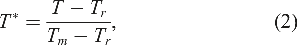
The Johnson–Cook (JC) associative flow rule is used to model the mechanical response of the metal alloys used in the projectile, flyer and witness plates. The constitutive law is as follows

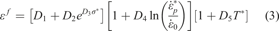
The Johnson–Cook dynamic failure model is implemented to account for damage of high-strain-rate deformation of metals. The strain at fracture is obtained from
Additionally, perforation resistance was used as a metric for calibration of the proposed model against experimental data. Here a study by Odermatt et al.
13
was used that propose a mathematical relation to predict the perforation depth, as
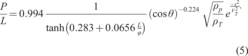
This experimentally derived formula was based on 99 tungsten penetrator tests which yield a maximum deviation of 3.3%, 14 which implies the relation is reasonably accurate.
Modelling of explosive reactive armour
Here, a variable pressure load is imposed which is assumed to represent an ERA detonation. We do not model the explosive explicitly. The Gurney equation
2
was used to calculate the maximum velocity of explosively driven flyer plates

Finite element modelling
Projectile and target parameters
A 25 mm diameter, 500 mm long monolithic tungsten projectile with a velocity of 1500 ms−1 was used for all tests. The majority of tanks that use ERA are based on the T72/80/90 chassis, where the upper glacis is angled at 68° NATO obliquity, as described by a declassified CIA report. 16 In our study, the ERA and the witness plate were mounted at a 68° obliquity angle.
Material parameters for tungsten & RHA steel. 4
RHA: rolled homogeneous armour.
Initial model calibration and convergence studies
All models were analysed using the general-purpose finite element software Abaqus/Explicit.
17
The choice of mesh size is crucial in obtaining reliable numerical results. Thus, a mesh convergence study was conducted to determine the appropriate mesh size to be used in the analysis. For this, a 100 mm thick RHA target plate was impacted by a cylindrical tungsten projectile of 25 mm diameter and 500 mm length orthogonally (at 0° obliquity). The external side faces of the model were held fixed in displacement (Figure 1(a)). The global symmetry of the model is used to increase computational efficiency. The projectile had an initial velocity and mass of 1500 ms−1 and 2.16 kg, respectively. The projectile element size was fixed at 3 mm, while the plate’s element size varied between 2 mm and 9 mm. The residual plate mass was recorded, and this value is plotted against the plate element size used I in the computation (Figure 1(b)). A polynomial fit of the results shows that for an element size less than 4 mm, a good convergence of results was obtained (note the variation of mass is small). A similar observation was made when considering the internal stress field variation with element size. For subsequent models, a plate element size of 4 mm was chosen (yielding an error of <10%), as this provided a good balance between computational efficiency and numerical accuracy. Mesh convergence study (a) a schematic of the model used with imposed boundary conditions (b) plot of plate mass remaining post-impact versus plate element size used.
Target and Projectile properties. 14
The outer side faces of the plate were held fixed (displacements were set to zero) with the bottom face free to deform, as shown in Figure 2(a). The total analysis time was set at 1250 μs, with no mass-scaling, and an initial projectile velocity of 1500 ms−1. The chosen velocity of 1500 ms−1 is based on a reasonable estimate of the projectile velocity of an APFSDS round. This velocity is commonly used in studies elsewhere.4,5 A master-slave interaction was assigned between the projectile and plate surfaces with self-contact. (a) 3D and (b) 2D section view of projectile-armour impact for calibration and convergence study.
The damage evolution values were calibrated to prevent complete projectile perforation as observed in experiments. The projectile’s damage evolution was fixed at 5 MJ which demonstrates the characteristic mushrooming of the projectile nose based on preliminary studies. The witness plate damage evolution value was then calibrated to prevent full perforation, which was set at 2.05 MJ.
A section view of the von Mises stress evolution of the calibrated projectile-armour impact at various times of the impact event is shown in Figure 3. At the end of the simulation, the projectile just stops short of full penetration. Evolution of plate erosion and von Mises stress in witness plate at (a) 31 μs, (b) 375 μs, (c) 1250 μs (end of simulation) with the projectile fully arrested.
These results indicate that despite the impact obliquity, the projectile does not deflect or deviate noticeably from its original flight path, with the penetration event taking approximately 800 μs with 97.5% of the projectile being eroded. The projectile residue remains at the end of the penetration channel which was also observed in experiments carried out by Odermatt. 14 Additionally, the rate of erosion was similar to those reported by Nezamabadi et al. 19
Explosive reactive armour modelling
Flyer and Explosive properties.
RHA: rolled homogeneous armour.
To calculate the plate acceleration, the Flis relation (equation (9)) was used to obtain the projectile velocity for a period of 500 μs in 5 μs intervals. Increments of 1 μs were used within the first 5 μs to characterise the sharp increase in acceleration at the initial stages. To compare with the predicted velocity curve, a pressure load was applied to the inner faces of the plates. To calculate the required pressure, the approximate acceleration between each time step was first calculated. The required pressure was then derived from the formula
This pressure profile was incorporated into the modelling software and the velocity output at the inner, central node of each plate was tracked. The comparison between the predicted velocity curve, using the Flis equation (equation (9)), and that obtained from the computational model is shown in Figure 4. A reasonable match was obtained (within 10%) with an excellent correlation at the early stages of acceleration. This gives us confidence that the proposed approach is reasonable and within an acceptable error margin Figure 4. Comparison between predicted and simulated flyer plate velocity.
Final model development
A complete model was developed, with the projectile and flyer plates with dimensions as before, with the witness plate thickness set at 150 mm (Figure 5). All components were meshed using the same technique as before, with a minimum element size of 3 mm for the projectile and 4 mm for the flyer and witness plates. (a) 3D and (b) 2D view of the final ERA model assembly.
The projectile’s longitudinal axis was aligned with the centre of the ERA sandwich (in the z-axis in Figure 5). The ERA was placed at a stand-off distance of 100 mm from the witness plate, with a gap of 10 mm between the two flyer plates to account for the explosive material. Both the ERA and witness plate were placed at 68° obliquity.
A pressure load was applied to the flyer plate inner surfaces (which accommodate the explosive). We assume that the pressure from the detonation would have a negligible direct effect on the projectile. The analysis time was 1300 μs in all models with no mass-scaling. Master-slave contact interactions were created between the components, except for the flyer plates and the witness plate. The overall modelling strategy followed is shown in Figure 6. Model setup and calibration strategy.
Results and discussion
The effect of varying stand-off distance was first analysed. With all parameters held constant, the stand-off distance was varied from 50 mm and 130 mm, in 10 mm increments. The projectile’s longitudinal axis was aligned with the ERA and witness plate centres. A schematic of the two extreme stand-off distance models is shown in Figure 7. The detonation delay, Minimum (a) and maximum (b) stand-off distance models.
We observe that an increase in stand-off distance increased projectile deformation. This was due to the additional time and distance for the projectile in flight before impact. The projectile displacement would increase from any ERA induced rotation.
In Figure 8, the temporal evolution of projectile impact for stand-off distances of 50, 90, and 130 mm is shown. A 60 μs delay results in the projectile not interacting with the second flyer plate, which causes a deep penetration cavity in the witness plate for all stand-off distances. The projectile deformation was observed to increase between the 50 and 130 mm stand-off tests, where a larger stand-off distance results in the projectile being greatly misaligned from its initial path of flight. This reduces the overall penetration (seen at 1300 μs). The perpendicular penetration depth, Temporal evolution of stress distribution for 
Next, we study the effect of increasing the detonation delay time to 150 μs. We observe that the projectile interacts with the ERA through a mechanism known as plate feeding. Plate feeding occurs when the ERA detonates as the projectile penetrates the second flyer plate without perforating it. Figure 9 shows the section view of the stress evolution of the 50, 90 and 130 mm stand-off distance tests. We observe an increase in projectile bending with an increase in stand-off distance which leads to the projectile tending to deflect off the plate inducing a shallower with a longer penetration cavity. The perpendicular penetration depths for the 50, 90 and 130 mm tests were 71, 52 and 44 mm, respectively, with the ERA resulting in a 65–75% reduction in penetration for the 50 and 130 mm stand-off distances, respectively. Temporal evolution of stress distribution for 
A final Temporal evolution of stress distribution for 
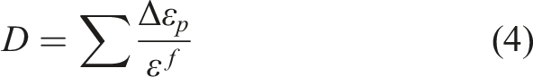
To further analyse the results of the tests, the minimum remaining plate depth, witness plate strain energy, and remaining plate mass were assessed across the range of stand-off distances. From the numerical data, we observe that the penetration depth reduced as the stand-off distance increased for all detonation delay cases, which implies that the minimum remaining depth in the witness plate increased with the stand-off distance. In Figure 11 the minimum remaining depth, Relation of remaining witness plate depth 
It is observed that the relationship between
Figure 12 shows the post-impact plate mass, Relation of residual witness plate mass 
The total strain energy, Relation of witness plate strain energy 
Here, we observe that the energy absorbed reduces with an increase in the stand-off distance, for all values of
Next, we assess the effect of varying the impact obliquity by introducing a small variation of Temporal evolution of stress distribution for t
D
= 200 μs and 90 mm stand-off distance, for varying angles of obliquity (63° and 73°). The perpendicular penetration depths 
Figure 15 shows the remaining depth for varying stand-off distance, at obliquities of 63°, 68° and 73° and t
D
= 60 μs, while in Figure 16 the remaining depth results for t
D
=200 μs are compared. Considering t
D
= 60 μs at 63° impact scenario, the gradient of the line is higher in comparison to the other cases. This is due to the 50 mm stand-off distance case study, which leaves a post-impact remaining depth of only 4 mm. As the projectile approaches the back face of the plate, the resistance from the plate decreases as there is less supporting material in the projectile’s path. This causes a transition from a semi-infinite target to a finite one, where the projectile effectively penetrates more into the target material due to its proximity to a free boundary. Relation of remaining witness plate depth (D) with stand-off distance at different obliquities, t
D
= 60 μs. Relation of remaining witness plate depth (D) with stand-off distance at different obliquities, t
D
= 200 μs.
For a detonation delay of 200 μs (Figure 16), the gradients of the studied obliquities are nearly identical, supporting the conclusion that the penetration depth is inversely proportional to stand-off distance regardless of detonation delay or obliquity.
An observation made during the obliquity tests was that for the t
D
= 150 μs, 68° obliquity angle and t
D
= 200 μs, 73° obliquity angle the remaining depth results were nearly identical. The contour plots of the stress field of the two simulations are similar with the flyer plates interacting with the projectile in the same manner, leading to a similar penetration cavity as shown in Figure 17. The interaction mode seen is plate feeding, which has already been identified to cause a substantial amount of penetration reduction. This is evident here, as despite the 73° witness plate having a 28% larger line-of-sight thickness than the 68° witness plate, the perpendicular penetration depth is only 2% different between tests. This further supports the conclusion that the interaction mode of the flyer plates has a much larger effect than the stand-off distance. Temporal evolution of stress distribution comparing the results of t
D
= 150 μs, 68° obliquity and t
D
= 200 μs, 73° obliquity for a stand-off distance of 90 mm. The perpendicular penetration depths 
The conclusions drawn and relations for
Concluding remarks
A study of the penetrative capabilities of a tungsten long-rod projectile was performed, with varying ERA stand-off distances from 50 and 130 mm, and detonation delay ranging from 60 μs to 200 μs. The following observations were made: • For the range of stand-off distances investigated, the residual penetration depth of the witness plate was found to be inversely proportional to the stand-off distance, regardless of detonation delay or obliquity angle. This only holds true if the projectile was able to fully interact with the moving flyer plates. Thus, for stand-off distances where the flyer plates impact the witness plate before the projectile has passed through them, the ERA’s effectiveness may drop significantly. • The detonation delay of the ERA governs the deformed shape of the projectile, thereby affecting its penetration capability significantly. This is due to the nature of the interaction of the projectile with the flyer plates, with plate feeding inducing the greatest reduction in projectile penetration. • In comparison to stand-off distance, detonation delay had a much larger effect on the residual penetration of the projectile, which can be tuned to improve armour efficacy. In reality, the stand-off distance is often limited by available space on the tank or armoured vehicle. Thus, the ERA should be mounted at its maximum possible stand-off distance ensuring that the flyer plates can fully interact with the projectile during impact.
The model developed is predictive and allows for an exhaustive study of impact scenarios not previously considered.
Supplemental Material
Supplemental Material
Footnotes
Declaration of conflicting interests
The author(s) declared no potential conflicts of interest with respect to the research, authorship, and/or publication of this article.
Funding
The author(s) received no financial support for the research, authorship, and/or publication of this article.
Supplemental Material
Supplemental material for this article is available online.
References
Supplementary Material
Please find the following supplemental material available below.
For Open Access articles published under a Creative Commons License, all supplemental material carries the same license as the article it is associated with.
For non-Open Access articles published, all supplemental material carries a non-exclusive license, and permission requests for re-use of supplemental material or any part of supplemental material shall be sent directly to the copyright owner as specified in the copyright notice associated with the article.