
Abstract
A numerical simulation was performed to investigate the effects of longitudinal vortices on the heat transfer enhancement of a laminar flow in a rectangle duct mounted with rectangular winglet pair on the bottom wall. The studied Reynolds number which was defined using the hydraulic diameter twice the channel height ranges from 500 to 7000. The comparisons of the fluid flow and heat transfer characteristics for the cases with and without rectangular winglet pair were carried out. The effects of the height and attack angle of vortex generator pair on the heat transfer performance were investigated. The results show that mounting rectangular winglet pair on the bottom wall of the channel can significantly enhance heat transfer. The distributions of secondary flow on the cross sections are consistent with the distributions of Nu and J for different attack angles. The maximum heat transfer performance is obtained when the attack angle is 29° due to the maximum value of secondary flow generated by rectangular winglet pair.
Keywords
Introduction
Heat exchangers are widely used in engineering field. Nowadays, it is very important to reduce energy consumption and material consumption, and thus to improve the efficiency of heat transfer exchanger. To design heat exchangers having good performance, the methods of heat transfer enhancement are used extensively. Heat transfer enhancement with small flow losses may be achieved by the generation of a structured secondary flow via longitudinal vortices. To produce longitudinal vortices, longitudinal vortex generators (LVG) are needed. Longitudinal vortices are kind of secondary flow on the cross section of a channel, and secondary flow can strengthen heat transfer enhancement efficiently. This method has received more attentions because it introduces relatively small pressure loss to enhance heat transfer. The reason is that the wall pressure loss depends mainly on the normal gradient of velocity component along the main flow direction on the wall and not on the gradient of velocity components formed secondary flow, so this method has been attributed to the heat transfer enhancement methods of the third generation. 1
The capacity of heat transfer enhancement of vortex generator (VGs) depends on their shape and other parameters such as attack angle and height of VG. According to the reports of Tiggelbeck et al., 2 the best performance is given by the delta winglets, closely followed by the rectangular winglets (RWs). Russell 3 carried out experimental study of a pair of embedded VGs on the channel and compared their heat transfer and pressure drop characteristics. It is found that a pair of embedded VGs is a superior method to enhance heat transfer.
A single longitudinal vortex embedded in turbulent boundary layer was experimentally studied by Eibeck and Eaton.4–7 Pauley and Eaton, 8 Fiebig et al., 9 and Turk et al. 10 studied the effects of longitudinal vortex pair embedded in turbulent boundary layer on heat transfer characteristics. The results show that the vortex pair decay slowly in a distance longer than that of a single vortex, and which has great impact on heat transfer.
Flow and heat transfer characteristics in channel with rectangular wing and triangular wing of different layouts have been investigated by Tian et al. 11 Wu and Tao12,13 studied heat transfer enhancement by punching RW and triangular winglet of rectangular channel in laminar fluid flow, and the results show that strong heat transfer enhancement and low coefficient of flow friction in the zone near the winglet is affected by punching holes in the wall. Didarul et al. 14 found that heat transfer with jagged arrangement rectangular wing is better than that with the same angle arrangement. Wang et al. 15 found that heat transfer is enhanced significantly when the LVGs are mounted in the narrow channel. Heat transfer of the fin surface of oval tube bank fin heat exchanger with the triangular wing in laminar flow was studied by Chu et al., 16 and they found that the average Nusselt number on the fin surface of heat exchanger with triangular wing increases from 13.6% to 32.9%, and the pressure loss increases from 29.2% to 40.6%. Joardar and Jacobi 17 studied heat transfer characteristics of tube bank fin heat exchanger with triangular winglets on the fin in laminar flow, and the results showed that heat transfer factor j is improved to 74% by winglets, and the friction factor f increases by 41%.
Based on available information that vortex pair contributes heat transfer enhancement more efficiently than a single VG does; in this article, a plate fin heat exchanger model mounted with RW vortex generator pairs is studied. The effects of Reynolds number, the height of rectangular winglet pair (RWP), and the attack angle are investigated using numerical method.
Physical model and mathematical formulation
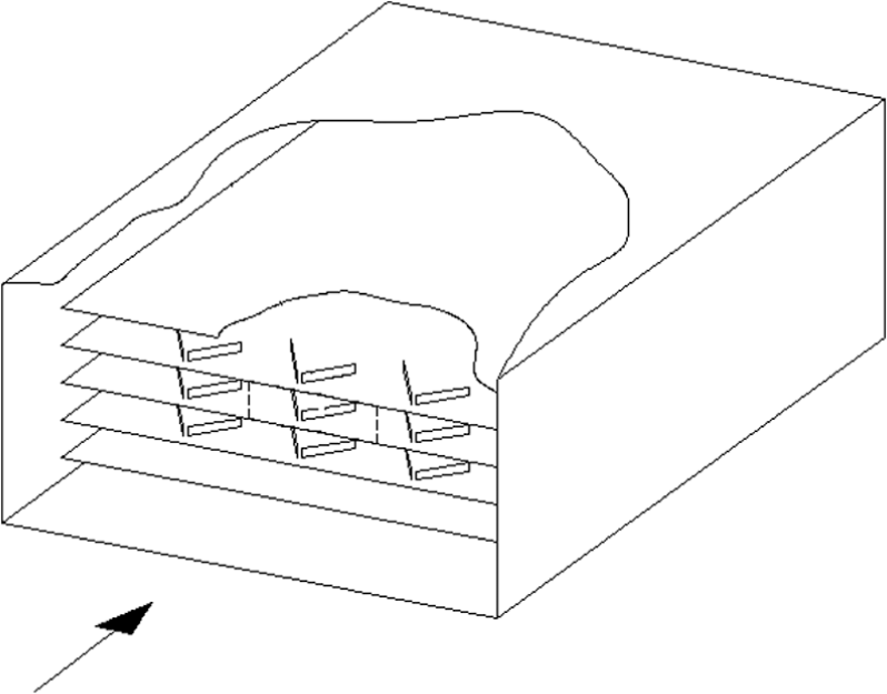
The physical model consists of multi-parallel plates each with a row of multi-RWPs as shown in Figure 1. To facilitate the study, we select a periodic domain having one rectangular VG pair as shown in Figure 2. The model geometry is H = 20 mm×B = 100 mm×L = 300 mm (height×breadth×length), the leading point of RWPs is located at a distance Xv = H from the inlet of the channel, the distance between the RWPs is S = 0.2H, the RW length size is l = 2H, the height of RWP regions from h = H/4 to H/2, and the angle of attack β ranges from 20° to 40°. The inlet air temperature is Ta = 42°C, and the wall temperature of the channel is Tf = 30.8°C.
Model with vortex generator pair.

Geometry of the air side of a plat fin heat exchanger.
In the analysis process, it is necessary to make the following simplifying assumptions: (1) fluid has constant properties; (2) the fluid flow is a steady laminar flow; and (3) without considering the fluid viscous dissipation and body force.
The compact forms of the governing equations in physical space are as follows:
Continue equation
Momentum equation

Energy equation
At the inlet cross section of fluid

At the outlet cross section of fluid

On symmetric surface, the velocity component along the normal direction of this surface is zero,

On the fin and RWP surfaces

For the second model, we used the characteristic length as follows

The Reynolds number and the friction factor are defined as follows

where L is the length of the channel as shown in Figure 2. The local and average Nu are determined as follows
The local convective heat transfer coefficient is determined as follows

where Tc is the characteristic temperature of the fin side fluid and is defined as follows

The average heat transfer coefficient is obtained through

where S is the total area of the heat transfer surface. At the same time, we define overall Nusselt number as follows

Numerical method
The schematic grid systems are presented in Figure 3(a). The governing equations are discretized there using the control volume method. 18 The power scheme approximation is used to discretize the convective terms, while second-order central difference scheme is employed for the diffusion terms. SIMPLE algorithm is used to couple the velocity and the pressure. 18 Within this algorithm, the momentum equations and pressure correction equation are solved sequentially and iterated to convergence. The collocation grid arrangement 19 is used in this study.

Simulation domain and grid system: (a) grid model and (b) locations of RWP and grid in plane of x-y.
A serious verification for the grid independence of the numerical solution has been made to ensure the accuracy and validity of the numerical results. As indicated in Table 1, the influence of increasing the grid size or reducing the grid size on the numerical results is very small. The maximum difference of Nu and f between the three grid systems is less than 4.0%. Therefore, the numerical solution is the grid independent solution. The results are calculated using the grid system of 114×103×32, as shown in Figure 3(b). As rectangular grids are used for the simulation domain, the RWP is approximated by small steps as shown in Figure 3(b). In order to keep the shape of the RWP, the grid number changes along with the change of attack angle and the grid sizes in three dimensions are proportional to each other.
Grid independence (Re = 6000, β = 30°, h = 10 mm).

To verify the reliability of numerical simulation program, Nusselt number of experimental results and numerical simulation results in the channel without RWP has been compared in the Reynolds number range of 500–7000, as shown in Figure 4. Where the parameter x* is defined as x* = x/DhRePr by Kakac et al., 20 Nux is average Nusselt number on the wall of the channel without RWP

Comparison of numerical result with experimental result.
It is found that the numerical results and experimental results are in good agreement, which indicates that numerical simulation program is reliable.
Results and discussions
Effect of Reynolds number
The ratio of the span-averaged Nu on the bottom wall of the channel mounted with RWP to the span-averaged Nu0 of the channel without RWP can be used to evaluate the heat transfer enhancement. Figure 5 shows the ratio of Nu/Nu0 under the conditions that Reynolds number ranges from 500 to 7000, and RWP has an attack angle of 30°. It is found that the heat transfer is not enhanced in the upstream region of RWP. Staring from the position where RWP is mounted, heat transfer is significantly enhanced by secondary flow generated by RWP, the maximum value of the ratio of Nu/Nu0 which indicates the heat transfer enhancement is about 175% at Re = 7000. At the same time, it is found that when Reynolds number is lower than 2000, heat transfer enhancement decreases downstream due to the decay of longitudinal vortex, especially in the outlet region of the channel. When Re is greater than 2000, the ratio of Nu/Nu0 increases downstream. The ratio of Nu/Nu0 increases with the increase in Re, but the heat transfer enhancement is not proportional to Reynolds number.

Distribution of Nu/Nu0.
The distributions of the ratio of local Nusselt number for model with RWP to that for model without RWP along y-direction are presented in Figure 6. Here, x′ = 0 corresponds to the rear end of the RWP. Figure 6(a) shows the comparisons of heat transfer enhancement at two positions with Re = 500. It is found that heat transfer is enhanced near the location of the RWP due to longitudinal vortices, and the heat transfer enhancement decreases downstream due to the decay of vortex. When Re = 2000, longitudinal vortices increases significantly, and the heat transfer enhancement increases, the difference of the ratio of Nu(x, y)/Nux0 at x′ = 2H and x′ = 8H becomes small, as shown in Figure 6(b). When Re ranges from 4600 to 6000, vortex can pass downstream for a long distance with large intensity, and the heat transfer enhancement at x′ = 8H is larger than that at position x′ = 2H. It is clear that secondary flow produced by RWP enhances heat transfer in the region far downstream.
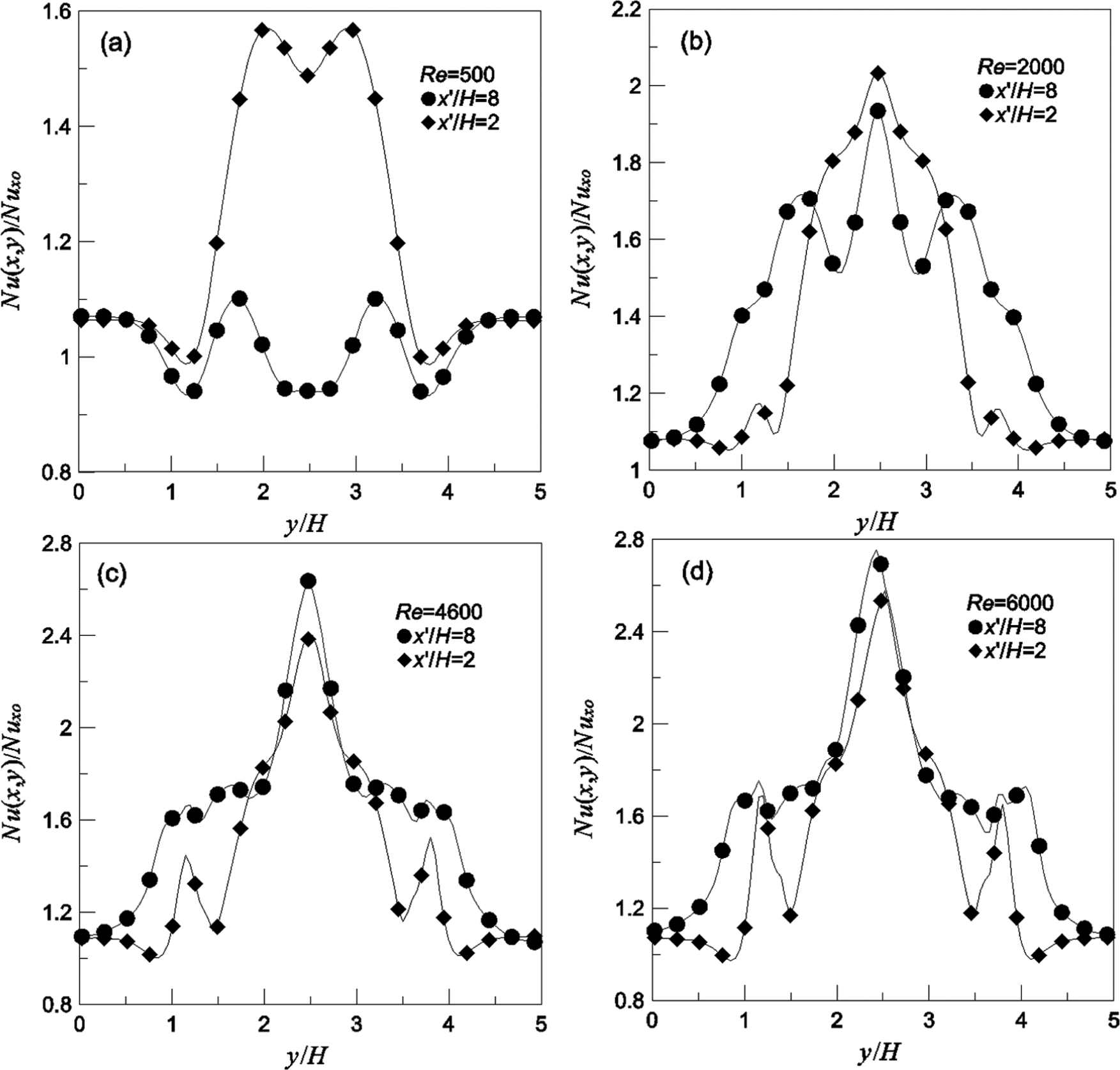
Distribution of Nu(x, y)/Nux0. (a) Re = 500; (b) Re = 2000; (c) Re = 4600; and (d) Re = 6000.
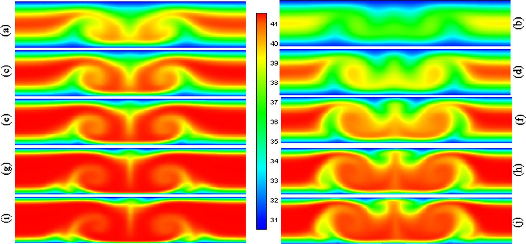
The velocity fields on the cross section of the channel are presented in Figure 7. These series of velocity fields give us clearly the developing of vortices in the channel corresponding to the position shown in Figure 6. Figure 7(a) shows the secondary flow on the cross section at the position x′ = 2H under Re = 500. Comparing to Figure 7(a), the intensity of secondary flow decreases at x′ = 8H as shown in Figure 7(b). Figure7(c) and (d) shows the secondary flow under Re = 2000, and it is found that the vortex decays with less degree downstream. Comparing Figure 7(f) with Figure 7(e), it is found that the intensity of the main vortices becomes weaker, but new vortices are induced upon the main vortices. Comparing Figure 7(b), (d), (f), and (h) with Figure 7(a), (c), (e), (g), it is found that the intensity of longitudinal vortices decreases along the main flow direction. A new pair of vortices is induced upon the main vortices at x′ = 8H when Re is greater than 2000.

Vortices on the cross sections at x′ = 2H and x′ = 8H under different Re numbers: (a), (c), (e), (g), and (i) x′/H = 2; (b), (d), (f), (h), and (j) x′/H = 8; (a) and (b) Re = 500; (c) and (d) Re = 1000; (e) and (f) Re = 2000; (g) and (h) Re = 4600; (i) and (j) Re = 6000.
Figure 8 shows the temperature fields at positions x′/H = 2 and x′/H = 8 under different Re numbers. It is found that the temperature fields at positions x′/H = 2 and x′/H = 8 change greatly under different Reynolds numbers. Temperature decreases obviously downstream, especially in the middle region of the channel. Such distributions of temperature in the channel are mainly caused by secondary flow. These show that VG pair has mixed fluid efficiently in most flow region. Therefore, heat transfer on the wall surface is enhanced in the region where vortices sweep over.
Temperature on the cross sections at x′ = 2H and x′ = 8H under different Re numbers: (a), (c), (e), (g), and (i) x′/H = 2; (b), (d), (f), (h), and (j) x′/H = 8; (a) and (b) Re = 500; (c) and (d) Re = 1000; (e) and (f) Re = 2000; (g) and (h) Re = 4600; (i) and (j) Re = 6000.
Figure 9 shows the distribution of local Nu along y-direction at x′ = 2H and x′ = 8H as a function of Re. The vertical axis means the ratio of local Nu for the model with RWP to the local Nu for the model without RWP. The ratio of Nu(x, y)/Nux0 increases with increasing Re. It is found that near the position of the VG pair at x′ = 2H, heat transfer characteristics are similar respecting to different Re numbers. When Re is larger than 2000, the difference between the values of Nu(x, y)/Nux0 for different Re numbers is small. At x′ = 8H, the difference between the values of Nu(x, y)/Nux0 for different Re numbers is obvious. When Re is less than 2000, due to the decay of vortices, the heat transfer enhancement caused by vortices is small; thus, the ratio of Nu(x, y)/Nux0 is not so large compared with that at x′ = 2H. When Re is larger than 2000, the vortex can pass downstream with a large intensity, and the heat transfer is obviously enhanced due to vortices coming from upstream. When Re is larger than 4600, the difference between the values of Nu(x, y)/Nux0 for different Re numbers is small, and the maximum value of Nu(x, y)/Nux0 at x′ = 8H is larger than that at x′ = 2H. When Re = 6000, the maximum value of Nu(x, y)/Nux0 at x′ = 8H is about 2.75, but it is about 2.56 at x′ = 2H.

Distribution of local Nusselt number under different Re numbers: (a) x′/H = 2 and (b) x′/H = 8.
Effect of the height of RWP
The effects of the height of RWP on heat transfer enhancement at the attack angle of 30° are shown in Figure 10(a). The span-averaged Nu increases with increasing the height of RWP. The ratio of Nu/Nu0 increases downstream which means that heat transfer enhancement will be more evident in the region far away from the RWP position. The difference of Nu/Nu0 for different heights of RWP decreases with the increase in the height of RWP, and the heat transfer enhancement does not increase proportionally to the height of RWP. The rate of drag coefficient increases greatly with increasing the height of RWP, as shown in Figure 10(b). The increase in the drag coefficient is proportional to the increase in height of RWP.

Distributions of Nu/Nu0 and Cf/Cf0: (a) Nusselt number and (b) drag coefficient.
Figure 11 shows the velocity fields on the cross sections at x/H = 7.5 and x/H = 11.25 when Reynolds number is 4600 and the heights of RWP h = H/2, 3H/8, and H/4. The vortices on the cross sections at x/H = 11.25 is weaker than that on the cross sections at x/H = 7.5. The vortices intensity decreases with the decrease in height of RWP. A new pair of vortices is induced upon the main vortices when the height of RWP is H/2, as shown in Figure 11(a) and (b).

Vortices on the cross sections at x/H = 7.5 and x/H = 11.25 under different heights of RWP: (a) and (b) h = H/2; (c) and (d) h = 3H/8; (e) and (f) h = H/4; (a), (c), and (e) x/H = 7.5; (b), (d), and (f) x/H = 11.25.
Figure 12 shows the ratio of Nu(x, y)/Nux0 at x′ = 2H and x′ = 8H for different heights of RWP when Re = 4600. It is found that Nu(x, y)/Nux0 increases with the increase in the height of RWP. Nu(x, y)/Nux0 gets peak values on the point of y = 2.5. The difference of Nu(x, y)/Nux0 for different heights of RWP in the region behind the RWP is obviously larger than that in the region far away from center of the channel. The maximum value of Nu(x, y)/Nux0 at x′ = 8H is larger than that at x′ = 2H when the height of RWP is greater than H/4. When the height of RWP is H/4, the value of Nu(x, y)/Nux0 at x′ = 8H is smaller than that at x′ = 2H. The reason is that the vortices intensity is weak when the height of RWP is H/4, and the vortices decreases quickly when passing downstream and the intensity of the vortices becomes much weaker at x′ = 8H compared with that at x′ = 2H.

Distribution of local Nu for different heights of RWP: (a) Re = 4600, x′/H = 2 and (b) Re = 4600, x′/H = 8.
Effect of the attack angle of RWP
The effect of attack angle on the drag coefficient and Nu under condition of h = H/2 is shown in Figure 13. It is found that when attack angle is 20°, the drag coefficient is about 1.32 times the value of the case without RWP. Nu is 1.24 times the value of the case without RWP. When the angle of attack is 29°, the drag coefficient increases to 1.6 times the value for the case without RWP, and Nu increases to 1.36 times of the value for the case without RWP. Further increasing the angle of attack to 40°, the value of the ratio of drag coefficient Cf/Cf0 is close to 1.9, while the value of the ratio of Nu/Nu0 is about 1.28. The drag coefficient increases proportionally to the increase of the attack angle of RWP, but the heat transfer enhancement is not proportional to the attack angle of RWP. When the attack angle is 29°, the heat transfer enhancement reaches to its maximum value, as shown in Figure 13(b).
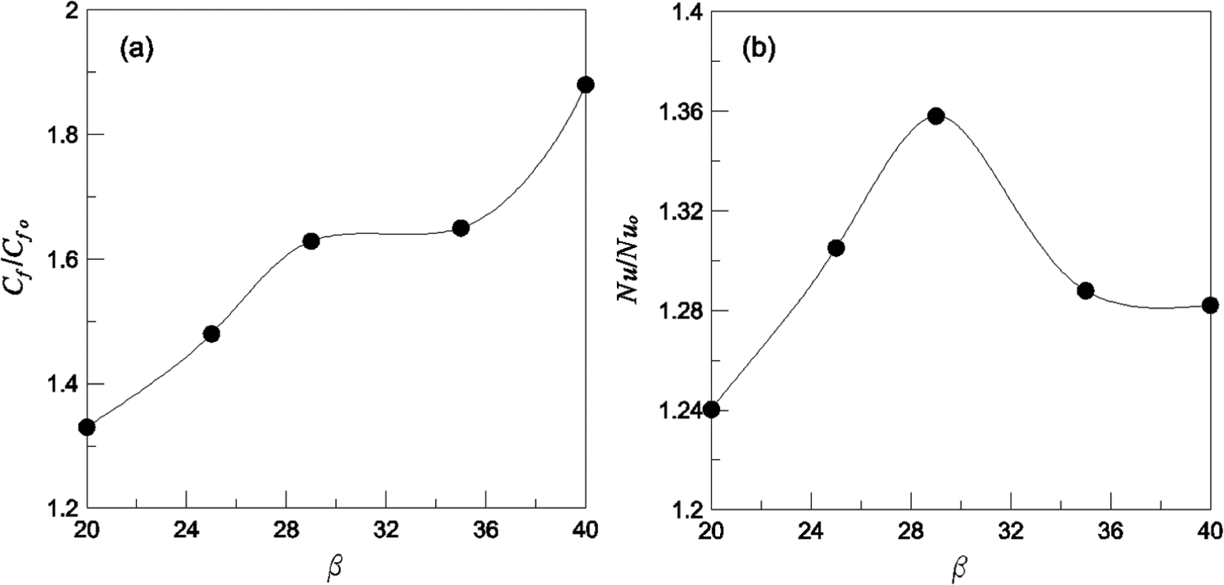
Distributions of Cf/Cf0 and Nu/Nu0 as function of β: (a) friction coefficient and (b) Nusselt number.
Figure 14 shows the distribution of the heat transfer enhancement factor as a function of attack angle. The heat transfer enhancement factor J is described as follows


Distribution of heat transfer enhancement factor J as function of β.
The factor J increases with the increase in attack angle when the attack angle is smaller than 29°. Then, J decreases with increasing the attack angle when the angle of attack is greater than 29°. The maximum value of J is obtained when the attack angle is 29°. Thus, the optimum attack angle of RWP is about 29°.
Figure 15 shows the velocity fields under different attack angles of RWP at x/H = 7.5 and x/H = 11.25. The intensity of secondary flow on the cross sections changes along with the changing of attack angle of RWP. The intensity of secondary flow increases with the increase in attack angle of RWP when the attack angle changing from 20° to 29°. Then the intensity of secondary flow decreases with increase in the attack angle changing from 29° to 40°. The maximum value of secondary flow intensity is obtained when attack angle is 29°. The distributions of secondary flow on the cross sections are consistent with the distributions of Nu and J shown in Figure 13(b) and Figure 14. Thus, the best heat transfer performance obtained when the attack angle is 29° due to the maximum value of secondary flow generated by RWP.

Vortices on the cross sections at x/H = 7.5 and x/H = 11.25 under different attack angles: (a) and (b) β = 40°; (c) and (d) β = 35°; (e) and (f) β = 29°; (g) and (h) β = 25°; (i) and (j) β = 20°; (a), (c), (e), (g), and (i) x/H = 7.5; (b), (d), (f), (h), and (j) x/H = 11.25.
Conclusion
In this article, numerical study of heat transfer enhancement with RWP mounted on the bottom wall of the channel is carried out. The same model without RWP is also carried out for comparison. The effect of the height of RWP and the attack angle of RWP on the heat transfer and pressure losing are studied. The distribution of span-averaged Nusselt number and the secondary flow generated by RWP on different cross sections under different heights and attack angles of RWP are also presented in detail. The distributions of secondary flow on the cross sections are consistent with the distributions of Nu and J for different attack angles. The maximum heat transfer performance is obtained when the attack angle is 29° due to the maximum value of secondary flow generated by RWP. Thus, the best heat transfer performance of the studied physical model can be obtained when the attack angle of RWPs is 29°.
Footnotes
Appendix 1
Academic Editor: Chin-Lung Chen
Declaration of conflicting interests
The author(s) declared no potential conflicts of interest with respect to the research, authorship and/or publication of this article.
Funding
The author(s) disclosed receipt of the following financial support for the research, authorship, and/or publication of this article: This study was supported by the National Natural Science Foundation of China (No. 51306086).