
Abstract
Multi-axle vehicles are widely used in several applications such as transportation, industrial, and military field, because of its higher reliability in comparison with conventional two axles vehicles. Despite that, there is a paucity of research studies that consider lateral stability enhancement of these vehicles, especially on rough terrain. This simulation-based research study fills this gap and introduces a new adaptive Active Rear Steering (ARS) controller that improves the lateral stability of an 8x8 combat vehicle for rough-terrain operation. The developed controller is designed utilizing the Integral Sliding Mode Control theory (ISMC) based on Gain-Scheduled Linear Quadratic Regulator (GSLQR). Besides, the GSLQR control gains are optimized by a Genetic Algorithm (GA) toolbox using a new synthesized cost function to ensure asymptotic stability. Furthermore, a new Adaptive-ISMC (AISMC) is introduced by using genetic programming to generate control equations that can replace the developed high-dimension GSLQR gains and facilitate future hardware implementation. The developed controller is evaluated by performing a series of simulation-based Double Lane Change (DLC) maneuvers on several rough terrains. The evaluation is conducted for both high friction and slippery surfaces at high and moderate speed, consequently. The results show high fidelity and robustness of the developed controller in comparison with a previously designed optimal LQR controller.
Keywords
Introduction
Vehicles lateral stability controllers are considered to be essential in all vehicles and crucial in maintaining the vehicles’ stability while performing a severe maneuver or cornering. Several vehicles lateral stability controllers are commercially available such as Electronic Stability Control (ESC), traction control, Torque Vectoring Control (TVC). All of these control systems aim to control and correct the vehicle yaw motion while steering. Generally, there are two techniques to control the vehicle yaw motion. The first is Direct Yaw moment Control (DYC) in which the controller utilizes the redistribution of traction forces on an individual wheel, in case of traction and TVC, or by applying and distributing braking forces on the wheels, in case of braking based controller such as ESC. The other method is controlling the vehicle yaw motion indirectly by controlling the steering angle of front axles, in case of Active Front Steering (AFS), or the rear axle, in case of Active Rear Steering (ARS), or all axles. Controlling the steering readjust the lateral force on each tire, which consequently adjust the vehicle yaw moment.
Several studies considered improving the vehicle stability using DYC, 1 ,4 which show high effectiveness in improving the vehicle lateral stability. However, DYC using differential braking deteriorates the vehicle longitudinal dynamic in case of excessive use. 5 Besides, it performs an aggressive and non-smooth control action, which reduces the Passengers’ comfort. In contrast, TVC is a smoother and effective alternative but it is relatively expensive and recommended to be implemented in electric vehicles.6,7 On the other hand, Active Steering Control has the advantages of being relatively low-cost and comfortable. Despite that, utilization of AFS is limited to a low steering angle to prevent violation of the driver command, which reduces its effective range, while the use of ARS is also limited because it produces noise and a feeling of driving a snow tire and makes the driver feel that the vehicle heads away from the trajectory in case of cornering, 8 which required a trained driver. Therefore, ARS can be used with no limitations in military vehicles as the drivers are skilled and trained.
Shibahata et al. 9 found that ARS increases the vehicle maneuverability and stability at low and high speeds, respectively. In addition, Zhang et al. 10 showed the effectiveness of ARS in reducing the sideslip and enhancing the tracking accuracy. Besides, the integration of ARS with other controllers can enhance the vehicle stability in various driving conditions and roads coefficient of friction, as discussed in references. 11 –13
In the field of vehicle stability control, there are more than 250 publications, 14 most of them considered the stability of 2-axles vehicles and only few studies the stability of multi-axle vehicles. Huh et al. 15 compared different steering configurations of a 6-wheel vehicle. The study showed that the handling characteristics of the vehicle are improved in case of 6-Wheel Steering (6 WS) than other configurations which were improved later by Chen et al. 16 using Linear Quadratic Regulator (LQR) controller. Later, an optimal 6 WS controller was introduced by Kim, Yi, and Lee 17 and Kim et al. 18 by constraining the lateral force to the friction circle. Moreover, the effectiveness of independent steering 3rd and 4th rear axles of an 8x8 combat vehicle was studied by Ahmed et al. 19 and compared with an ARS with fixed 3rd axle as in Russel. 20 Based on the available publications, still, there is a lack of research study that discusses the stability of multi-axle vehicles and rarity in those that consider off-road or rough terrain operation.
In general, contentious change of the vehicle parameters makes it hard to be controlled. The gain-schedule-based controllers offer a solution for that problem as introduced in references2,21–23 However, it is difficult to ensure the stability of the scheduling law and smooth control action as the operating conditions change.24,25 Alternatively, Sliding Mode Control (SMC) is widely used in vehicle stability systems due to its ability to cope with modeling uncertainties and disturbances. Tange et al. 26 introduced a High-order SMC to decrease chattering while sustaining the robustness of a front steering-based lateral dynamic controller of an unmanned vehicle. Ma et al. 27 developed a fuzzy-based SMC to enhance the vehicle stability according to the variation in the variation in the tires’ cornering stiffness. Recently, Subroto et al. 28 introduced a novel Adaptive Sliding Mode Control (ASMC) using an adaptive proportional integral sliding manifold to compensate for the road friction uncertainties and actuators malfunction. Also, an ASMC was exploited by Li et al. 29 to compensate for parameters uncertainties of 4 in-wheel electric motors that are used to improve the stability of an electric vehicle. Liu et al. 30 utilizes two separate super twisted SMC to control the front axle steering and the yaw moment to avoid vehicle crash while negotiating a single lane change maneuver. Despite the robustness and effectiveness of SMC, the implementation of a nonlinear controller is not easy to be achieved. 31
The contributions of this study are to introduce a new synthesized cost function to optimize a gain-schedule controller in order to ensure the stability of the closed-loop control system at all operating conditions with minimal control effort. Besides, genetic programming is used to introduce a control low that can replace the generated high-dimensional gain-scheduled controller to overcome implementation complexity in the future. Furthermore, due to the lack of research studies that cover multi-axle vehicles’ stability over rough terrain, this article fills the gap and introduces an ISMC-based controller to enhance the stability of an 8 × 8 combat vehicle that is operated on rough terrain at different driving conditions. The results are discussed in detail following virtual testing and evaluation in comparison with an optimal LQR controller that was introduced in detail in a previous study. 19
Disturbed vehicle mathematical model
Multi-axle combat vehicles have advantage over conventional two-axle vehicles due to better distribution of the vehicle’s weight on the axles. This reduces the pitch motion during acceleration and deceleration.
18
In addition, it was found in a previous study that ARS can improve vehicle rollover dynamics. Furthermore, this research considers only the lateral stability of the vehicle when driving on rough terrain, which is highly affected by the vehicle’s yaw rate and sideslip. Therefore, a bicycle model (Figure 1) that represents the vehicle motion in the yaw plane is used in order to design the controller, which will be implemented in the full vehicle model that includes 22 degrees of freedom that includes the pitch and roll motions of the vehicle’s sprung mass. The following assumptions are applied to linearize the bicycle model: Only motion in the X-Y plane is considered. Constant longitudinal speed. Assuming small steering and slip angles. All tires have the same characteristics. Tires have linear characteristics. Wheel kinematics are not considered. Negligible pitch and roll Load transfer. External disturbances are bounded.
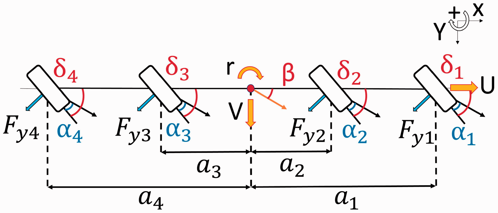
Bicycle model for an all-wheel steer vehicle. 19
The equation of motion in the lateral direction can be presented as in equation (1) where, m is the vehicle mass, V and U are the vehicle lateral and longitudinal velocities, r is the yaw rate, and Fyi is the lateral force act on ith axle. In addition, any disturbance wd to the vehicle such as side wind or road irregularities can be presented as a force and moment disturbance Δ
Fy
and

The lateral force can be calculated using linear tireses can be presented as a force and equation (2) where,


By letting the vehicle sideslip β equal to

Also, the 1st and 2nd axles are mechanically linked with the steering ratio c21 as in equation (5).

Furthermore, the summation moment about the Z-axis can be represented as in equation (6), where Izz is the vehiclee summation moment about the same axis.

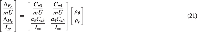
By substituting from equations (2) to (5) in equations (1) and (6) the state-space equation presenting the vehicle’s yaw motion can be presented as a function of the vehicle yaw rate and sideslip as in equation (7), which is equivalent to equation (8).
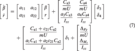
Where
Adaptive Integral Sliding Mode Controller design procedures
The vehicle is subjected to a continuous variation in the driving parameters and road conditions such as the vehicle velocity and the road surface friction. Besides, the road profile irregularities and side wind can produce a disturbance that can be assumed as an additional yaw force and moment to the vehicle motion. Therefore, this section discusses the design procedures of a new Adaptive Integral Sliding Mode Controller (AISMC) for an ARS system to enhance the handling performance and stability of the 8x8 combat vehicle when driving at various speeds on rough terrain with different friction coefficient. In general, Integral Sliding Mode Control (ISMC) is synthesized from two control terms; linear and nonlinear controllers. In this section, the linear term is designed based on (Gain Scheduled Linear Quadratic Regulator) GSLQR so the discontinuous (nonlinear) term gains are also scheduled according to it.
Optimal GSLQR
LQR is an optimal controller, however, it is developed based on a certain design point that is represented by the nominal model parameters, so the effectiveness of the controller can be decreased when operated far from these parameters. Therefore, the proposed controller gains are determined at different speeds to cover all possible operating speeds. Hence, the state-space equation can be represented as a function of the vehicle longitudinal speed as in equation (9). Moreover, the maximum desire states (r and β) can be represented as a function of vehicle’s speeds and road coefficient of friction (iμ) according to equations (10) and (11), respectively where g denotes the gravitational acceleration
32


Eventually, by solving the Riccati equation (12) that minimizing the performance index in equation (13)
33
the controller gains K can be calculated as in equation (14). In these equations ν represents the varied parameters, P is a positive definite matrix, Q and R are the states and control effort weight matrices, respectively. The final control input is then scheduled as a function of the vehicle longitudinal velocity and road coefficient of friction as in equation (15).


Generally, if a linear system represents a nonlinear one and is found to be asymptotic stable, it indicates that the nonlinear system is also stable.
34
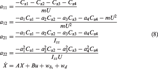
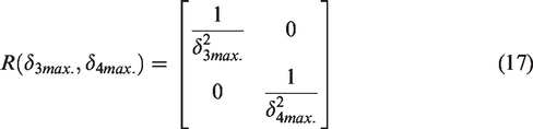
Hence, the weights matrices Q and R are continuously optimized for each design parameter variation to ensure asymptotic stability with real negative eigenvalues of the closed-loop control system. The weights matrices Q and R are presented according to Bryson’s rule
35
–37 and optimized based on a free constant positive number CQ, the maximum allowable average steering angle of the

Genetic programming-based Gain-Scheduled Linear Quadratic Regulator
In the late 90 s, an evolutionary optimization algorithm known as Genetic Programming (GP) was introduced by John Kozaa. Following the same concept of Genetic Algorithm (GA), GP uses the techniques of mutation, crossover, and natural selection. GA is usually used to produce a bit-string representation of a certain problem. On the contrary to GA, GP deals with string data type that presents genetic operators to synthesize an algorithm and apply it to the same problem. 38 Hence, GP generates arithmetic functions and operations in a hierarchical structure to generate a solution to the problem based on the inputs (terminals). In addition, GP applies the genetic operators on the algorithm/equation in form of branches as in Figure 2. 39
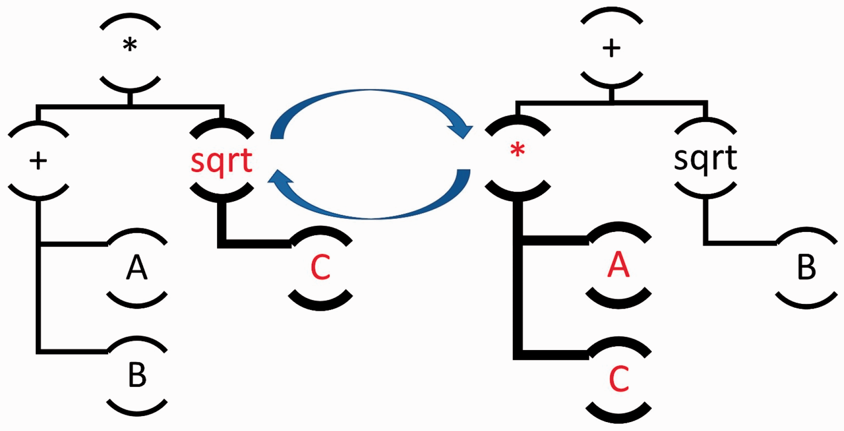
Genetic programming structure.39
In this section, a genetic programming tool provided by Eureqa software is utilized to represent each scheduled gain by a simple and single optimum equation that can replace and reduce the dimension of the developed GSLQR gains. This technique permits increasing the resolution of the varied parameters and includes more design points in the GSLQR design regardless of the burden of resulting in high-dimensional gains data-set. Besides, it facilitates future hardware implementation of the controller. Another advantage of using this method is to interpolate between the design point and allow a smooth transition from one point to another and extrapolate for points beyond the one included in the design.
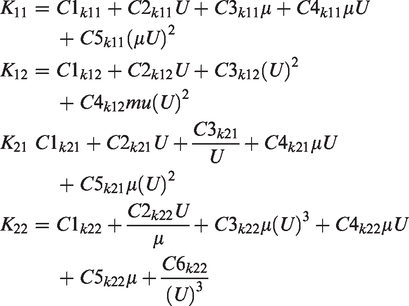
GP is used to represent the GSLQR gain to the one illustrated equation (19), which will be stated as GP-GSLQR in the rest of this paper, as a function of the vehicle’s speed and road’s friction where Cnkij denote real constant values. Moreover, to simplify the output equations and consequently reduce the complexity and computational effort, the solution is constrained to basic math operators (*, protected division/, −, +).

where
Integral Sliding Mode Controller design
SMC is known for its effectiveness and robustness in disturbance rejection and parameters uncertainties, however, this compensation only starts after reaching the sliding manifold. On the contrary, ISMC has the ability to compensate for that disturbance and uncertainties from the beginning and without the existence of the reaching phase.
40
Lets consider the disturbance wd in equation (8) is bounded and can be presented as matched disturbance equals to
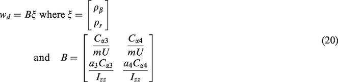
ISMC is structured form two terms linear controller that controls the nominal system without considering the disturbance and a nonlinear discontinuous control term to compensate for the existed bounded disturbance. The proposed controller includes the developed GP-GSLQR, which is designed based on a linear control theory to stabilize the nominal system at various driving conditions and a nonlinear control term as in equation (22)

The sliding manifold S of the ISMC is designed and scheduled according to equation (23) where, GSC is a projection matrix that satisfy equation (24), Xo is the system’s states initial condition.


Eventually, the discontinuous controller is presented as in equation (25) and the sign function is approximated according to equation (26) using a very small positive constant ϵsmc to prevent chattering phenomena.


Controller evaluation
A nonlinear 22 degrees of freedom 8x8 combat vehicle model was developed to represent the vehicle motion and validated in references.41,42 The model was implemented in TruckSim software for research purposes to conduct all virtual testing, which shows high fidelity in several research studies.19,43–45 The vehicle is equipped with 4-axles and independent suspensions and powered by an internal combustion diesel engine. In addition, four mechanical differentials, one per axle, are utilized to distribute the engine torque to each axle. The vehicle model uses the steering of the front two axles with the capability of steering the
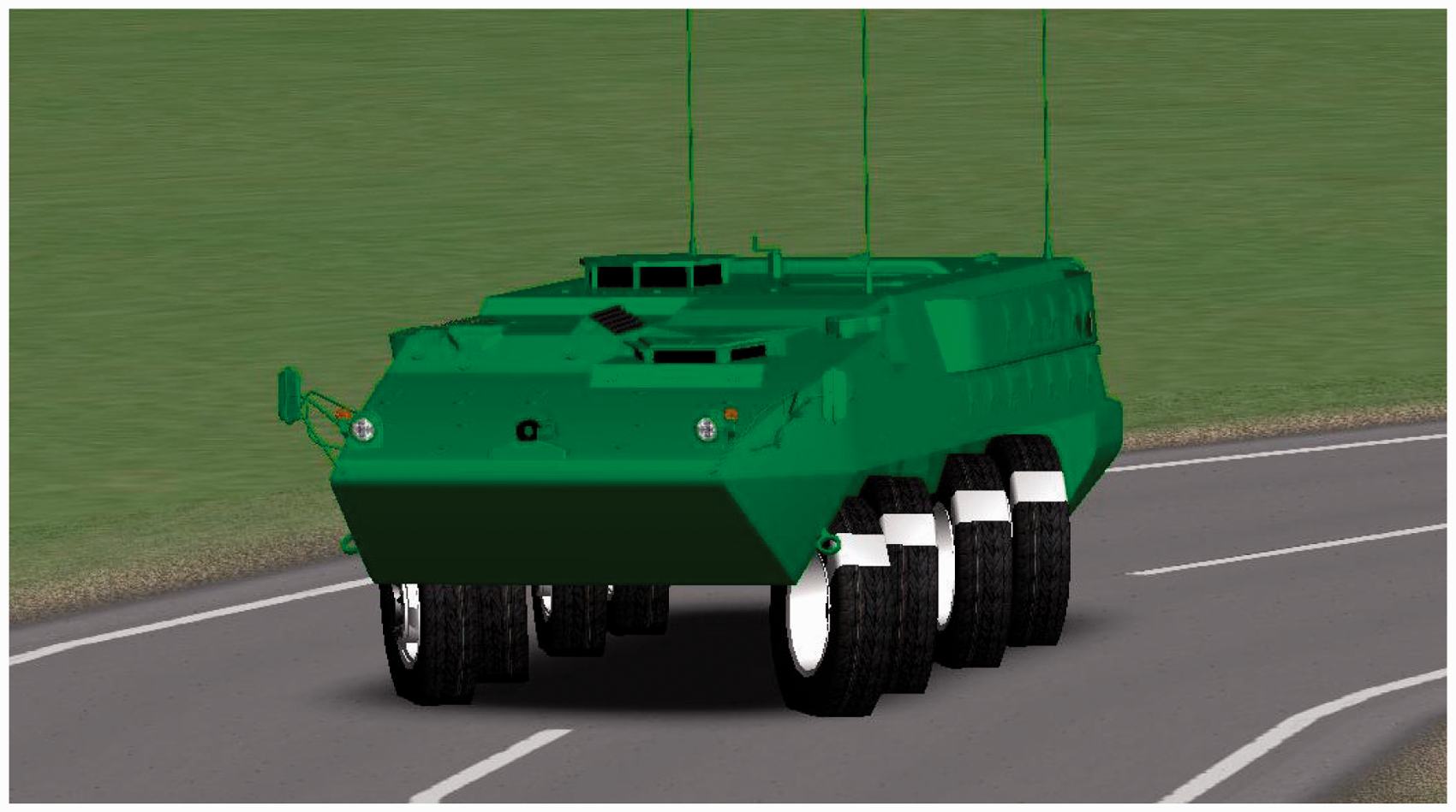
3D cad model of the all-wheel steer 8x8 combat vehicle on TruckSim software. 19
Evaluation on rough terrain
At first, the controllers are tested on a road with uniform irregularities as shown in Figure 4. The road surface profile is presented as a sinusoidal wave with a wavelength of
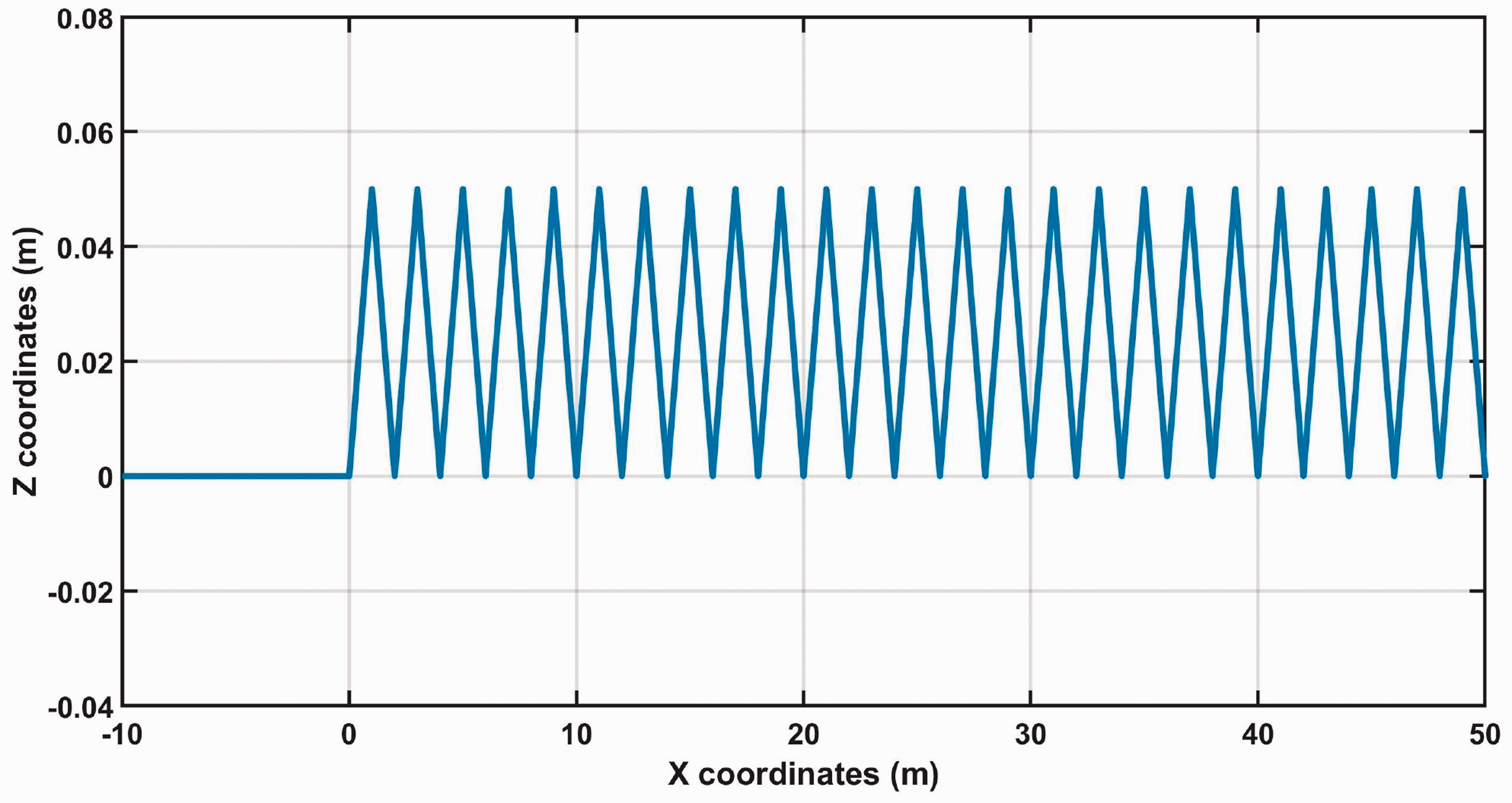
Profile of the road surface irregularities in the vertical direction.
Figure 5(a) illustrates the vehicle trajectory when it was driven with speed
DLC on a road with
Figure 6 shows the corresponding average steering angle for the
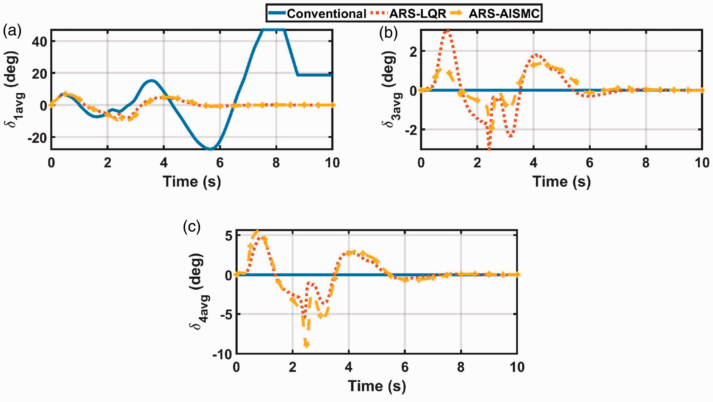
DLC on a road with
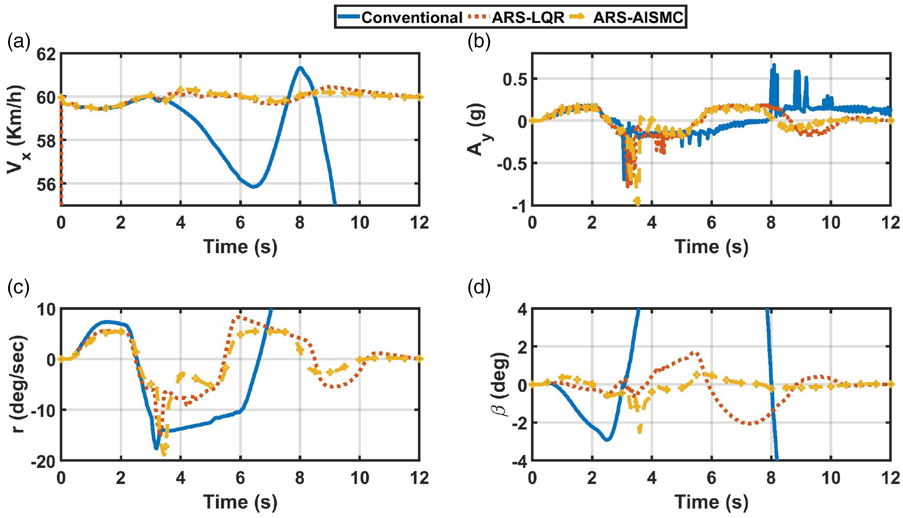
The vehicle dynamic response is illustrated in Figure 7. It can be seen that the fluctuation in the vehicle longitudinal velocity and lateral acceleration is the same for each case as in Figure 7(a) and (b), respectively. Meanwhile, the yaw rate and vehicle’s sideslip response of the ARS-AISMC is less than the ARS-LQR as in Figure 7(c) and (d), respectively, which indicates higher stability.
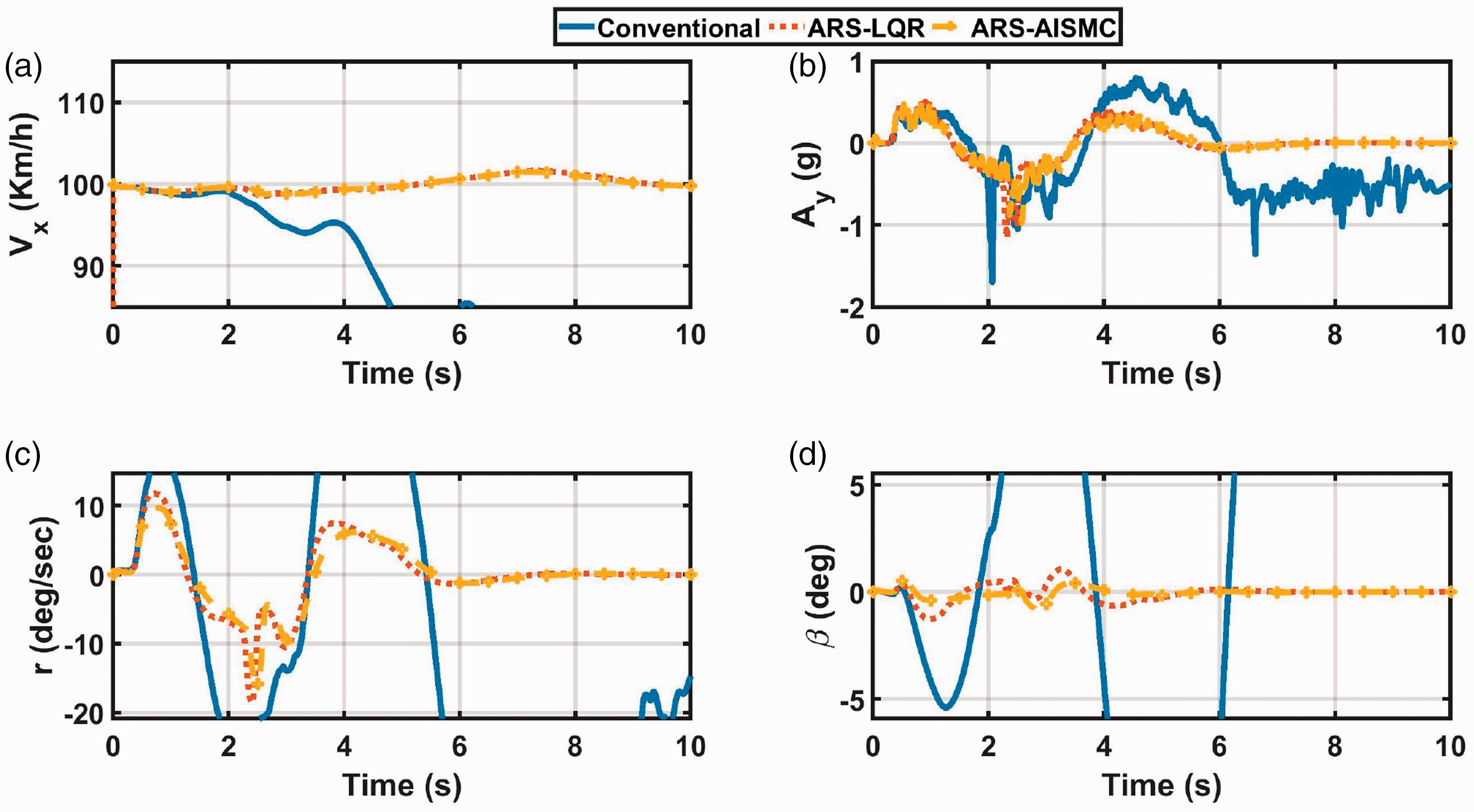
DLC on a road with
The controllers are evaluated at
DLC on a road with
Figure 9 shows the steering axles’ average steering angles. The average
DLC on a road with
The longitudinal velocity and lateral acceleration almost respond the same for both controllers as in Figure 10(a) and (b), respectively. Meanwhile, Figure 10(c) shows low differences between the controllers at the beginning. However, the ARS-AISMC shows a lower yaw rate and the end and faster stabilization than ARS-LQR. This result can be confirmed by observing lower vehicle sideslip of the ARS-AISMC and higher stability than ARS-LQR as in Figure 10(d).
DLC on a road with
Evaluation on extreme rough terrain
In this section, the previous road’s surface profile is superimposed with an extreme rough profile as shown in Figure 11. First, the controllers are tested on a road with a high coefficient of friction (0.85) and the vehicle is driven with speed
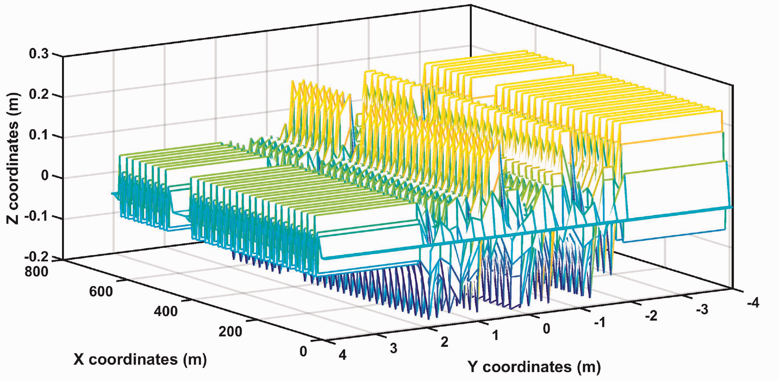
Profile of the road surface irregularities.
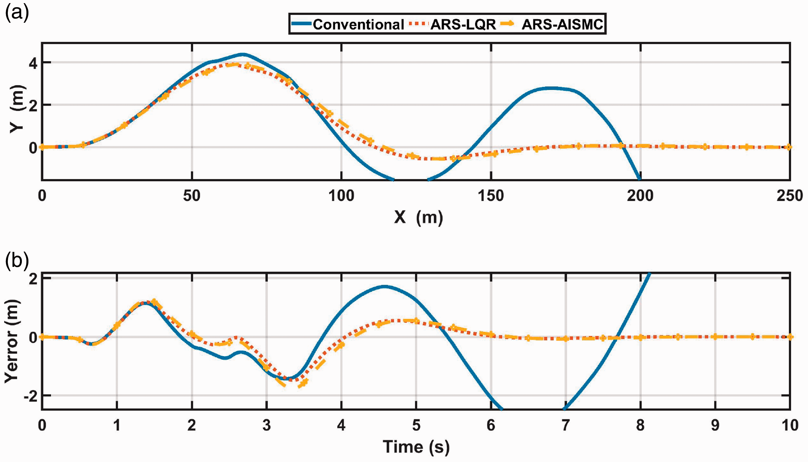
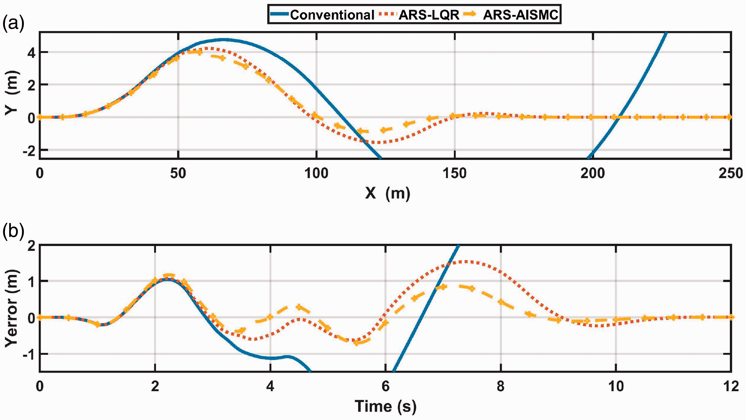
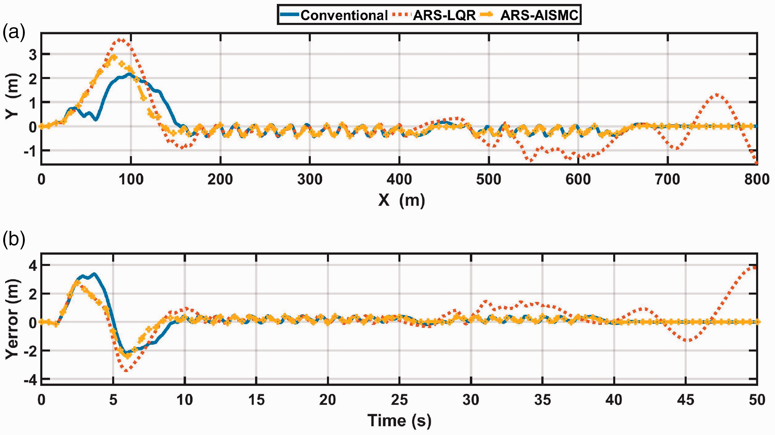
The vehicle trajectory and corresponding lateral error are illustrated in Figure 12(a) and (b), respectively. It can be noticed that the conventional vehicle couldn’t be stabilized after the maneuver. On the other hand, the controlled vehicle could successfully finish the maneuver resulting in almost the same lateral error. It is also noticed that the conventional vehicle has the lowest steerability (maneuverability) as it performed the minimum lateral distance for the maneuver, as shown in Figure 12(a).
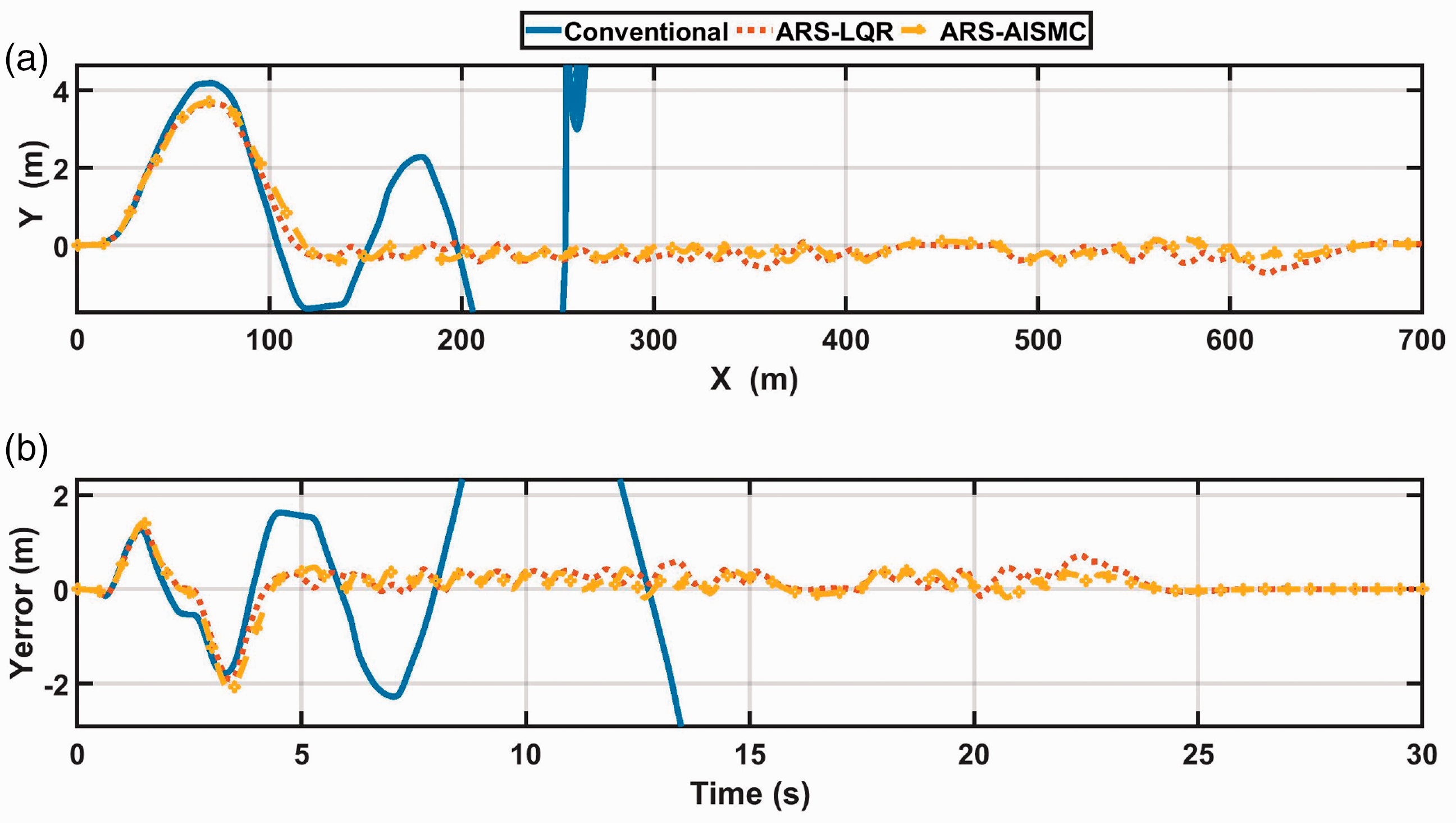
DLC on a road with
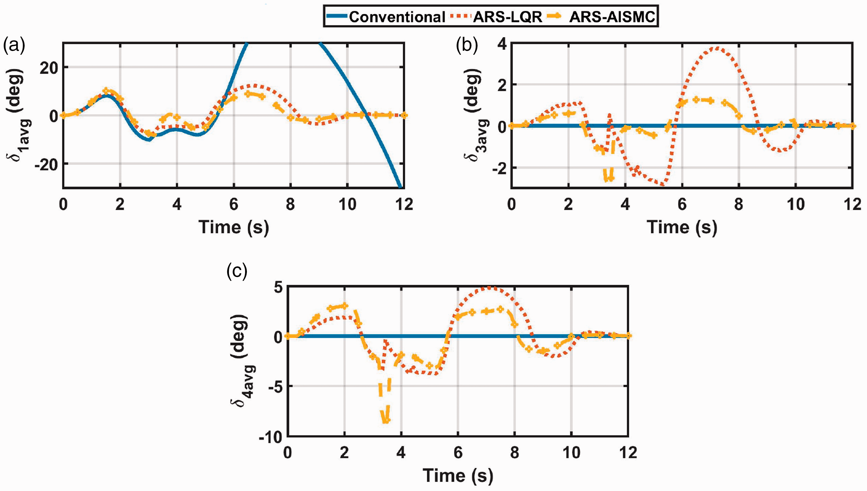
Figure 13(a) shows the average steering angle of the
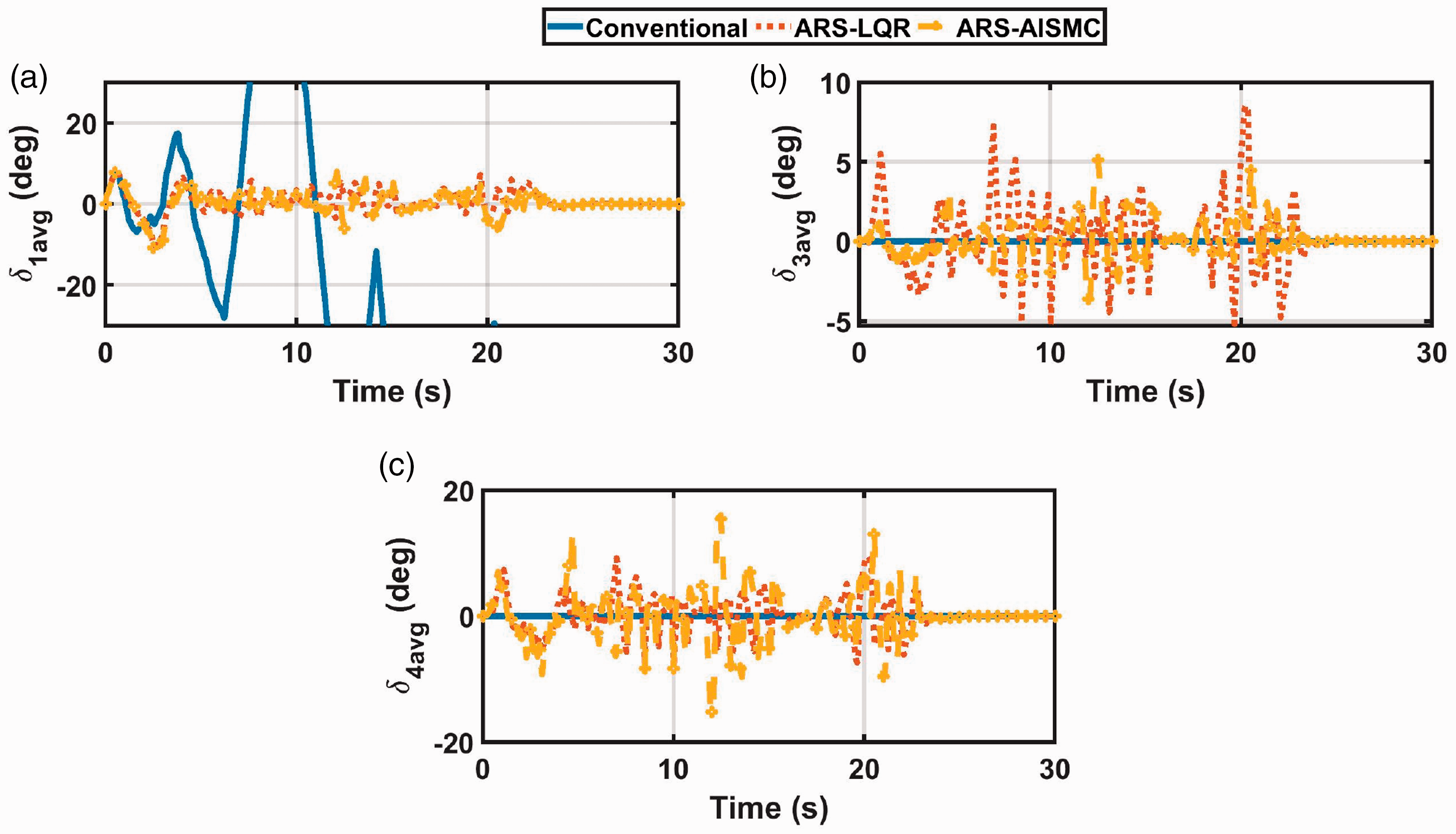
DLC on a road with
The vehicle dynamic response in Figure 14 doesn’t show a considerable difference between both controllers and it can be seen that both controllers almost follow the same behavior and longitudinal speed profile as in Figure 14a and can limit the vehicle yaw rate and sideslip, as in Figure 14(c) and (d), respectively. Meanwhile, the high lateral acceleration in Figure 14(b) indicates that wheels lift-off the ground due to the high speed and high irregularities, however, rollover didn’t occur.
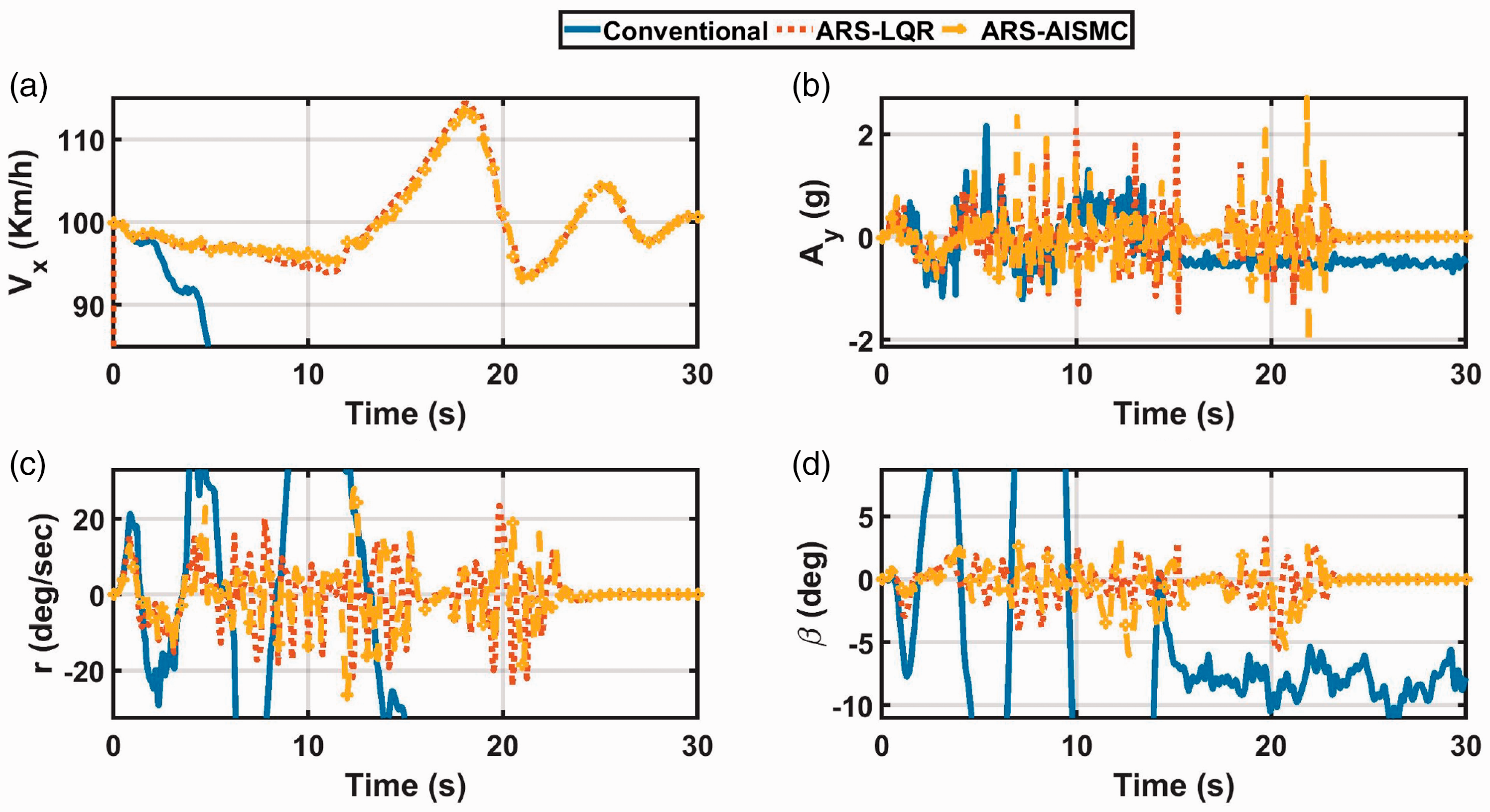
DLC on a road with
When repeating the maneuver at a slippery surface with a coefficient of friction
DLC on a road with
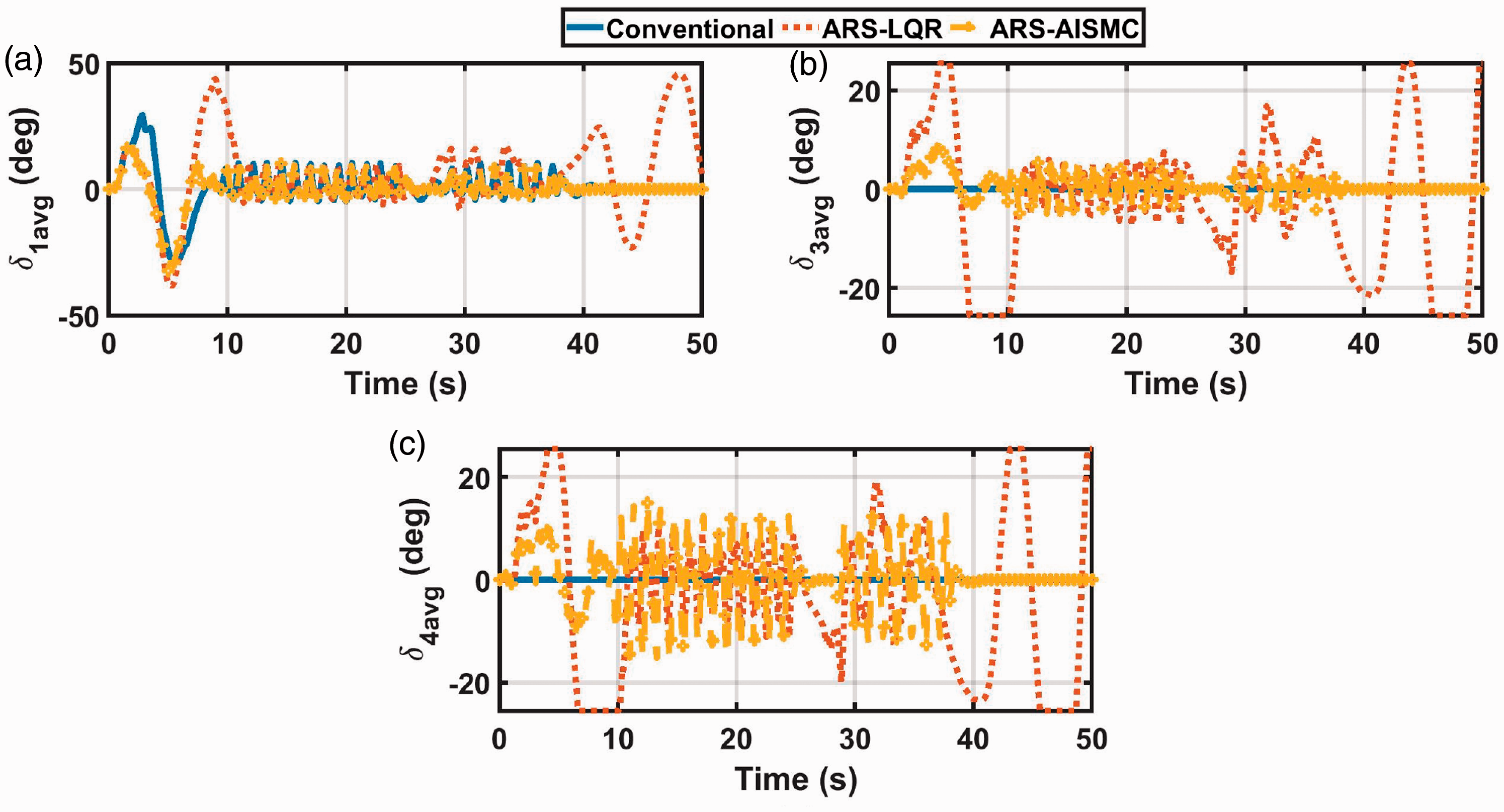
In Figure 16, the ARS-AISMC shows the minimum consumption of the steering actuators with a low average steering angle than all cases in Figure 16(a), and lower than the ARS-LQR in Figure 16(b) and (c).
DLC on a road with
By observing the fluctuation in the vehicle’s longitudinal velocity in Figure 17(a), it can be seen that the ARS-LQR is exposed to high fluctuation (more than
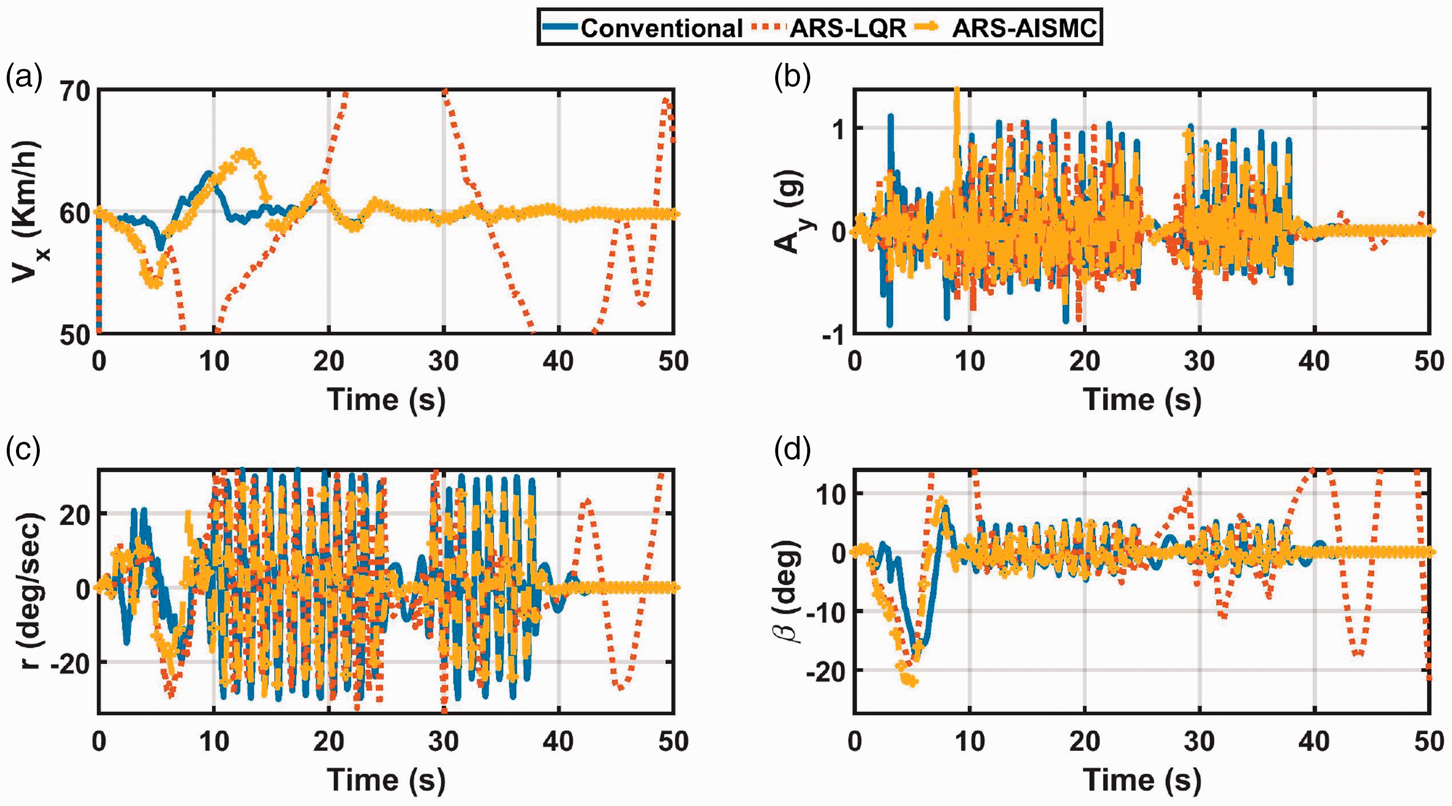
DLC on a road with
The failure of the ARS-LQR to stabilize the vehicle in comparison to the conventional vehicle is related to several reasons. The first is associated with the less lateral offset that is taken by the conventional vehicle, as shown in Figure 15(a). This small lateral offset resulted in less yaw rate and sideslip, hence, better stability but limited maneuverability. On contrary, the vehicle controlled by the ARS-LQR exhibits higher lateral offset (and demonstrates better maneuverability). Another reason is the large steering angles that are exhibited by the ARS-LQR on the rear axles (
Conclusions
In this article, a novel adaptive-Integral Sliding Mode Controller (AISMC) of an Active Rear Steering (ARS) system is introduced. The developed controller includes a gain-scheduled Linear Quadratic Regulator (GSLQR), which is optimized using a new synthesized cost function that has the following advantages: Minimizing the control effort by utilizing relatively small rear steering angles Ensure asymptotic stability of the closed-loop controlled system. Generally, the closed-loop asymptotic stability can facilitate the development of an Integral sliding mode-Composite Nonlinear Feedback (ISMC-CNF) Controller which can introduce high performance in case of actuator saturation.
46
The controller relies on minimizing the vehicle sideslip and limiting the vehicle yaw rate, which facilitates introducing zero reference signals and made the controller has no dependency on the reference model accuracy.
Moreover, Genetic Programming (GP) was utilized to replace the high-dimension GSLQR with four non-complex equations to develop GP-GSLQR that has the following preferences: Smooth transition between the control gains at various driving conditions, because of the interpolation. Extrapolation for driving conditions beyond the range that is used to develop the GSLQR and train the GP-GSLQR. This technique can simplify hardware implementation of the developed controller on a microprocessor for future work.
The article also shows that road irregularities can be introduced as a matched disturbance, which can be compensated using an integral sliding mode controller. This is used along with the developed GP-GSLQR to develop the introduced ARS-AISMC. Evaluating the controller and compare the results with the uncontrolled vehicle and the ARS-LQR controller show that: The controller is able to improve the vehicle lateral stability for both uniform and extreme road irregularities. Minimum actuator consumption is introduced by the developed controller, which indicates lower power consumption and higher life cycle. In general, the developed ARS-AISMC can stabilize the vehicle faster than the ARS-LQR. The vehicle maneuverability is drastically decreased when driving on the slippery-extreme irregular road profile, however, the ARS-AISMC introduces higher stability and better maneuverability than the uncontrolled vehicle and the ARS-LQR controller.
For future work, an active suspension control system will be developed to improve the riding comfort and vehicle’s sprung mass leveling, which will be integrated with the developed lateral stability controller to maximize the vehicle performance while driving on rough terrain.
Supplemental Material
sj-zip-1-pic-10.1177_09544062211009926 - Supplemental material for A novel adaptive-rear axles steering controller for an 8 × 8 combat vehicle
Supplemental material, sj-zip-1-pic-10.1177_09544062211009926 for A novel adaptive-rear axles steering controller for an 8 × 8 combat vehicle by Moataz Ahmed, Moustafa El-Gindy and Haoxiang Lang in Proceedings of the Institution of Mechanical Engineers, Part C: Journal of Mechanical Engineering Science
Footnotes
Declaration of Conflicting Interests
The author(s) declared no potential conflicts of interest with respect to the research, authorship, and/or publication of this article.
Funding
The author(s) received no financial support for the research, authorship, and/or publication of this article.
References
Supplementary Material
Please find the following supplemental material available below.
For Open Access articles published under a Creative Commons License, all supplemental material carries the same license as the article it is associated with.
For non-Open Access articles published, all supplemental material carries a non-exclusive license, and permission requests for re-use of supplemental material or any part of supplemental material shall be sent directly to the copyright owner as specified in the copyright notice associated with the article.