
Abstract
Control and structural health monitoring sensors are becoming increasingly common in industrial and household applications due to recent advances reducing their manufacturing costs, size and power consumption. Nevertheless, providing power for these sensors poses a key challenge to engineers, particularly in system locations where limited access renders regular maintenance infeasible due to high associated costs. In the present work, the design and physical prototype testing of a nonlinear electromagnetic vibration energy harvester is presented based on a previously reported concept of the authors. The harvester is activated by the torsional speed fluctuations of a rotating shaft. Experimental testing in a rig driven by an electric motor confirms the harvester’s properties and the modelled oscillatory behaviour. This novel rotational vibration energy harvester concept may generate over 10 mW of electrical power for a broadband speed range of approximately 400 rpm (in the examined rotational system with set fluctuating speed) for wireless sensing purposes on rotating shafts.
Keywords
Introduction
Various industrial applications (such as marine, aerospace, automotive, renewable energy) comprise propulsion systems that commonly exhibit rotational speed fluctuations, which are periodic in nature. This undesirable oscillatory energy excess can potentially be harvested to power sensors (eliminating the need for using batteries) for structural health monitoring and system control purposes. Self-powered sensing systems are an emerging trend, where recent advances in miniaturisation, cost and power requirements of wireless sensors have led to their increased use in a wide range of applications. Vibration Energy Harvesting (VEH) aims to harness ambient oscillatory energy for powering wireless sensing nodes.
The application of VEH in systems, where the primary motion is translational has been thoroughly investigated. 1 On the other hand, there is a dearth in the literature with regard to VEH for rotational applications. Trimble et al. 2 and Trimble 3 developed an electromagnetic energy harvester for random torsional drill speed fluctuations in oil well drilling systems. The device used a linear spring, generating energy most effectively at resonant conditions (as it is usually the case with VEH). However, if the driving excitation frequency drifts away from the harvester’s resonance frequency, the amount of generated power decreases rapidly. Hence, research has been focusing on broadening the useful frequency bandwidth of vibration energy harvesters. Kim 4 designed an energy harvester employing piezoelectric cantilever beams, which stiffen as the shaft speed increases. The aim was to harness energy from the second order speed fluctuations of an internal combustion engine, but the amount of generated power was insufficient for sensing.
Gu and Livermore 5 adopted a self-tuning mechanism (in a shaft rotating at constant speed) where the centrifugal acceleration effectively stiffens a beam with a bonded piezoelectric substrate. Variations of this approach have been developed to achieve the same self-tuning effects.6–9 The inherent bending stiffness of the beam though introduces a discrepancy between the tuned resonant frequency and the shaft rotation frequency. A further work by Gu and Livermore 10 employed a beam with a proof mass at its end, which impacts a piezoelectric element. The advantage is the reduced stiffening effect of the beam compared to the tensioning effects that tune the beam. Alevras and Theodossiades 11 presented a rotational energy harvester concept that utilizes centrifugal forces acting on rotating beams and induced preload to adjust the harvester’s modal frequency to the frequency of oscillations without affecting the vibrating inertia.
Other researchers applied VEH on automotive rotating components.12–14 Wang et al 12 and Roundy and Tola 13 used offset pendulums to tune their energy harvesters so that they always resonate at the driving frequency of the wheel. However, the centrifugal forces are hampering the operation of this device, causing excessive friction. Tang et al 14 used a magnet falling through a tube to excite piezoelectric cantilevers. The proof mass though may get trapped at one or the other end of the tube, deteriorating the performance of the harvester. A hybrid energy harvester from torsional motions has been developed by Trigona et al. 15 including a pendulum-based converter, piezoelectric converters and a solar energy harvester. The experimental measurements showed that the device has potential to operate at low frequency, and for a broad frequency range. It has to be noted that pendulum concepts have been popular for energy extraction from rotating components,16–18 not in a rotordynamics context though.
Nonlinear VEH concepts have been traditionally used in translational applications to broaden the usable frequency range of the harvester. Masuda et al. 19 have developed a control system that tracks the higher energy stable branch of a duffing mechanical oscillator, thus improving the power output of the harvester over a wide frequency range. Gunn et al. 20 presented an electromagnetic energy harvester concept for a rotating propulsion system shaft. Magnetic levitation was used, as in Mann and Sims, 21 to achieve a duffing-type nonlinear system. Alevras et al. 22 found that variation in stiffness, in combination with asymmetric forcing, leads the concept described in Gunn et al. 20 to multiple resonance zones, comprising mono-stable and bi-stable dynamics. In another work, Alevras et al. 23 investigated the nonlinear dynamics of the Mathieu oscillator, also considering cubic stiffness for broadband energy harvesting. It was demonstrated that the effectiveness of the parametrically excited system is not constrained by the effective frequency range of the duffing oscillator.
Gun et al.24–26 presented a nonlinear energy harvester concept for rotational applications. The harvester is essentially a rotor brushless permanent magnet direct current (DC) motor connected to a rotating shaft by a spring with cubic stiffness coefficient of nonlinearity. The harvester dynamics gave rise to a condition where a jump down frequency of the occurring Duffing oscillator (harvester) is unattainable due to the frequency dependent vibration amplitude increasing the jump down frequency as the excitation frequency increases.24,25
The design of broadband vibration energy harvesters for rotational systems – in particular propulsion applications – has been the main motivation behind this work. This originates from the ever increasing requirements to obtain accurate, real-time information for structural health monitoring during operation, without the use of batteries and harnessing. A physical prototype of a nonlinear (duffing-type) electromagnetic vibration energy harvester for rotational applications is presented. The prototype has been developed based on a previously discussed concept of the authors24–26 and validates the associated modelling work. The cubic stiffness coefficient of nonlinearity is induced in the harvester using conical springs. The performance of the nonlinear vibration energy harvester is compared against a linear counterpart, demonstrating that the nonlinearities can broaden the frequency bandwidth compared to the linear equivalent. The predicted generated power suffices to drive a sensing node for structural health monitoring purposes of the propulsion system. A nonlinear vibration energy harvester prototype that can be used in rotordynamic systems (for broadband operation) has not hitherto been reported in the associated literature, to the best knowledge of the authors.
Energy harvester concept
The concept of the proposed electromagnetic nonlinear vibration energy harvester is briefly explained in this section. This comprises a balanced rotor mounted on an oscillating shaft (so that it can rotate with respect to the axis along the shaft length) and a nonlinear torsional spring connecting the rotor to the shaft. Figure 1 shows the free body diagram of the rotor. The design challenge is first to numerically determine the properties of the energy harvester (rotor inertia, elasticity connecting the rotor to the oscillating shaft and damping mechanism) and then to implement these by developing and manufacturing a physical prototype that performs according to specific power output requirements (over 10 mW of electrical power for a few hundred rpm of shaft speed). The rotor is experiencing base-type excitation due to the acceleration of the shaft, as well as excitation due to the electromechanical interactions in the energy harvester.
25
The corresponding equation of motion is given by:


The suggested cubic nonlinearity is an essential feature of this design, since it aims at broadening the useful frequency range of the energy harvester compared to a device with a linear spring. The key assumptions are: (i) The mass of the rotor is sufficiently small compared to the shaft mass; (ii) The motion of the rotor has no effect on the shaft motion and (iii) The oscillatory motion of the shaft is the main excitation source of the energy harvester. Since the rotor is fully balanced, if the shaft were to rotate at constant speed, the rotor would follow at the same speed (after any transients had vanished). However, if the shaft exhibits rotational speed fluctuations, these will excite the rotor leading to oscillatory relative motion ϕ (between the shaft and the rotor).
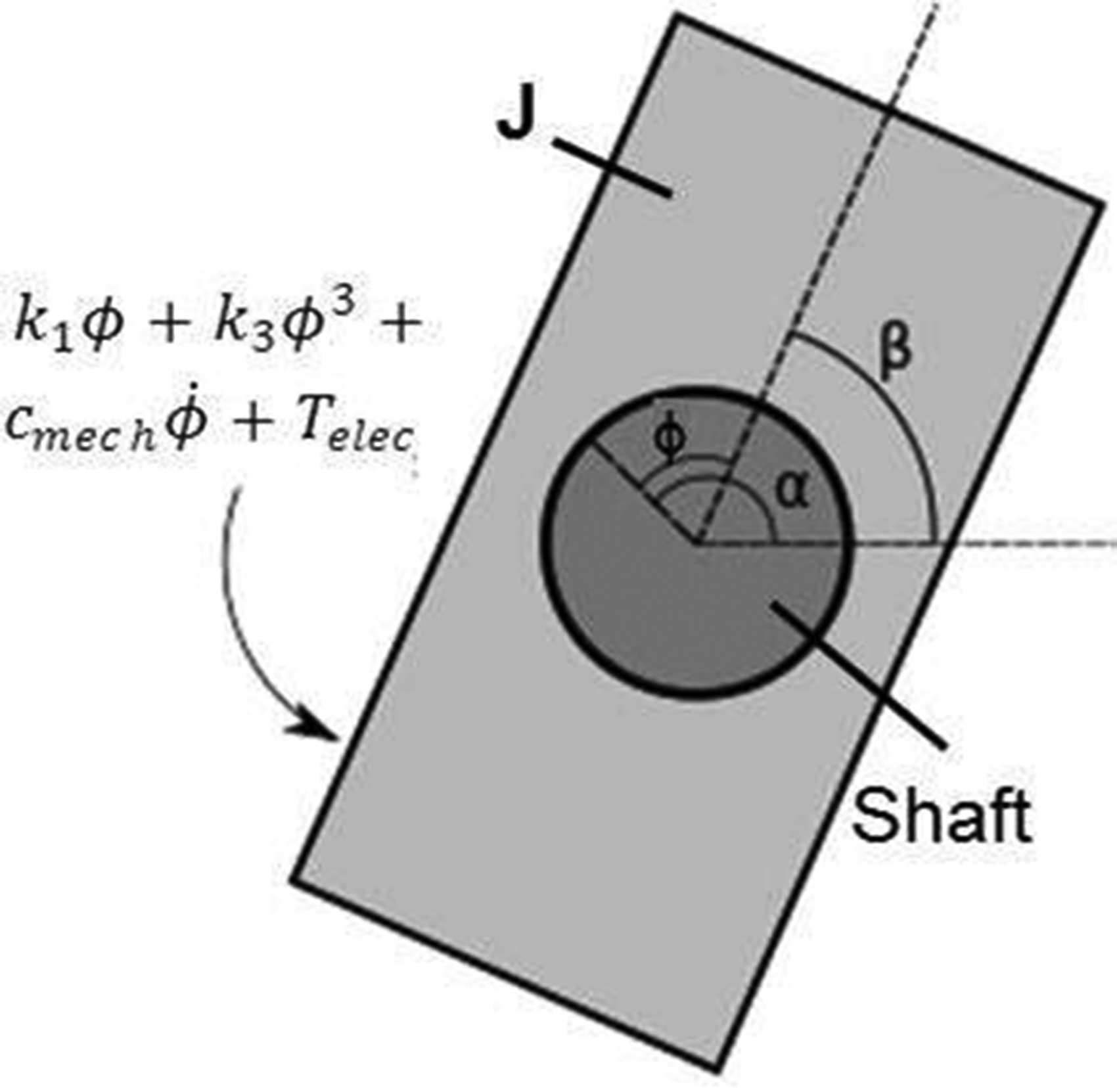
Free body diagram of the energy harvester.
A remaining feature of the system is related to the ability of the harvester to generate electrical power via the relative motion ϕ. This is done utilising magnets attached to the rotor, which can move relative to a coil of electrical conductor rigidly mounted on the shaft. As the rotor moves relative to the coil, an electromotive force (emf) is generated in the coil in accordance with Faraday’s law. The coil is connected to an electrical load. For the sake of simplicity, this can be now seen as a resistor but ultimately a wireless sensor node would be the anticipated load to enable measurements of the rotating system’s performance.
Figure 2 shows the simplified circuit diagram of the electrical load. The emf (ε) generated in the coil acts as a source term and is connected in series through the coil’s internal resistance, Rint, and load resistance, Rload. The electrical inductance of the coil has been assumed to be negligible. The generated emf is given by:


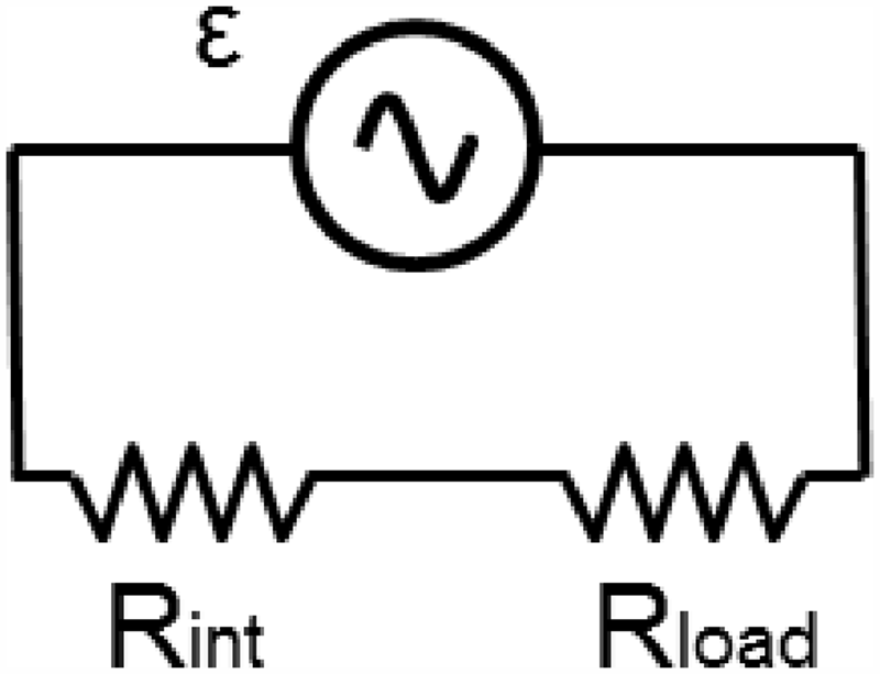
Electrical load circuit schematic.
Using the Rayleigh energy dissipation function (rate at which the energy is dissipated from the system proportionally to velocity), the electrical damping coefficient

Therefore, the equation of motion takes the following form that will be used hereafter to assess the response of the energy harvester:

Due to the coupled electrical damping term, the electrical power as a result of the mechanical response can be calculated.
The condition

Equations (6) and (7) can be now used to determine the motion of the harvester and the electrical power generated at the load.
Electromagnetic coupling factor
The proposed energy harvester utilises magnets with axial facing poles. The same approach as in Owens and Mann 28 is used to describe the electromagnetic coupling with the only exception being the equations for the magnetic flux density, since rectangular magnets and coils are used in the present work (to provide increased coupling factor per unit volume). Figure 3 shows the arrangement of the magnets and a single coil turn (conductor) used in the energy harvester. The magnet dimensions are depicted as coordinates of opposite corners in the cuboid representing the magnet. The magnetisation vector is shown using an arrow at the end of each magnet.
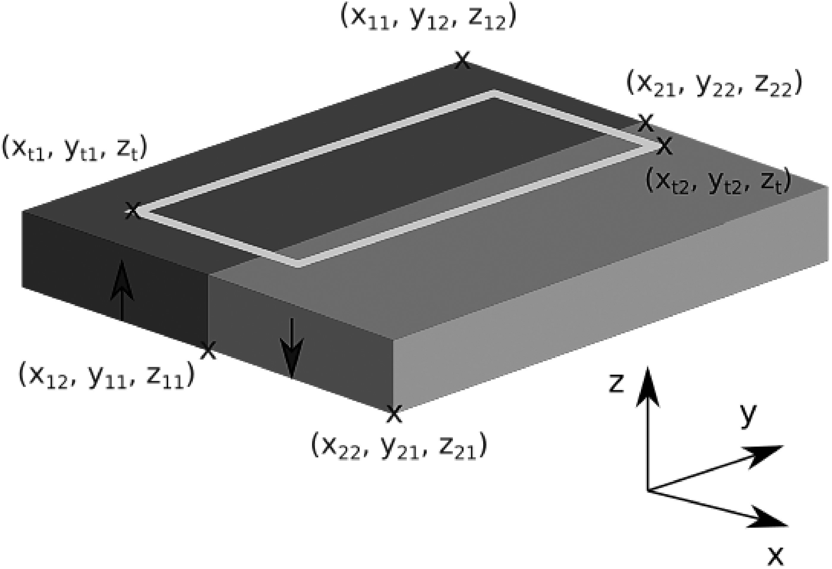
Magnet arrangement and a single coil turn (conductor).
The flux through a single coil turn is found by integration of the magnetic flux density, B, through the area it encloses. The furthest coil turns are at a large distance relative to the size of the magnet; thus, it cannot be assumed that the flux is constant through the entire coil. Only the magnetic field component perpendicular to the coil area contributes to the generated emf. Hence, only the z component of the magnetic field is calculated. The magnetic flux density at any point in space around a rectangular bar magnet (perpendicular to its face) is given by
29
:
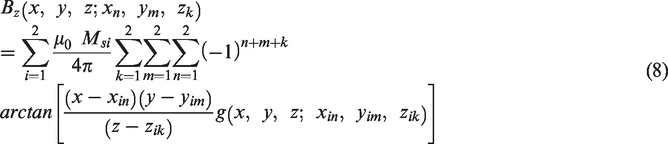
The function g(x, y, z; xin, yim, zik) is given by:

The mean flux per turn is found by integration of equation (10) over the full coil (as depicted in Figure 4), where subscript” t” denotes the inner most turn of the coil and the dimensions wc and dc are the coil cross sectional total width and depth, respectively. The total flux is then divided by the cross-sectional area of the conductor to calculate the mean flux per turn:
Full coil arrangement with respect to magnets.
Equation (11) can be evaluated numerically and the resulting mean flux per turn is multiplied by the total number of coil turns to find the total flux through a coil:

Differentiation of equation (12) with respect to time shows that all the parameters of equation (8) are constant except the position of the coil relative to the magnets. Hence equation (3) becomes:

Equation (13) is evaluated throughout the range of the rotor’s motion and the numerical integration of equation (6) uses interpolation to determine the coupling factor at every rotor position. Table 1 summarises the dimensions of the magnets and coil used in the prototype.
Main dimensions of the magnets and coil used in the prototype.
Nonlinear behaviour of the conical springs
The required force-deflection profile of the conical springs is determined using the MITCalc spring force tool. 30 MITCalc has been used (in a closed loop process) to define dimensions of conical springs that can match off the shelf springs based on the desired force-deflection profile that has been returned by the simulations employing equation (6) (according to the power requirements for the energy harvester). Besides the spring force calculations, force-deflection profile plots and spring strength calculations were conducted (to accelerate the design process) using different materials and design parameter variations to help choosing conical springs that will perform in a robust manner.
Conical springs have two force-deflection regimes. For smaller deflections the behaviour is linear; however, above a critical load, the coils start to bind, and the behaviour becomes nonlinear. For energy harvesting purposes the nonlinear regime is of particular interest. The main dimensions and properties for round wire conical springs are shown in Table 2, whereas a spring schematic is presented in Figure 5. The threshold, below which the force-deflection profile is linear, is given by
30
:
Main dimensions and properties for a round wire conical spring.
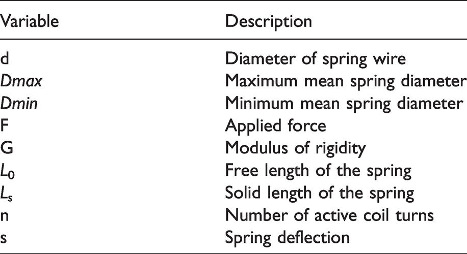
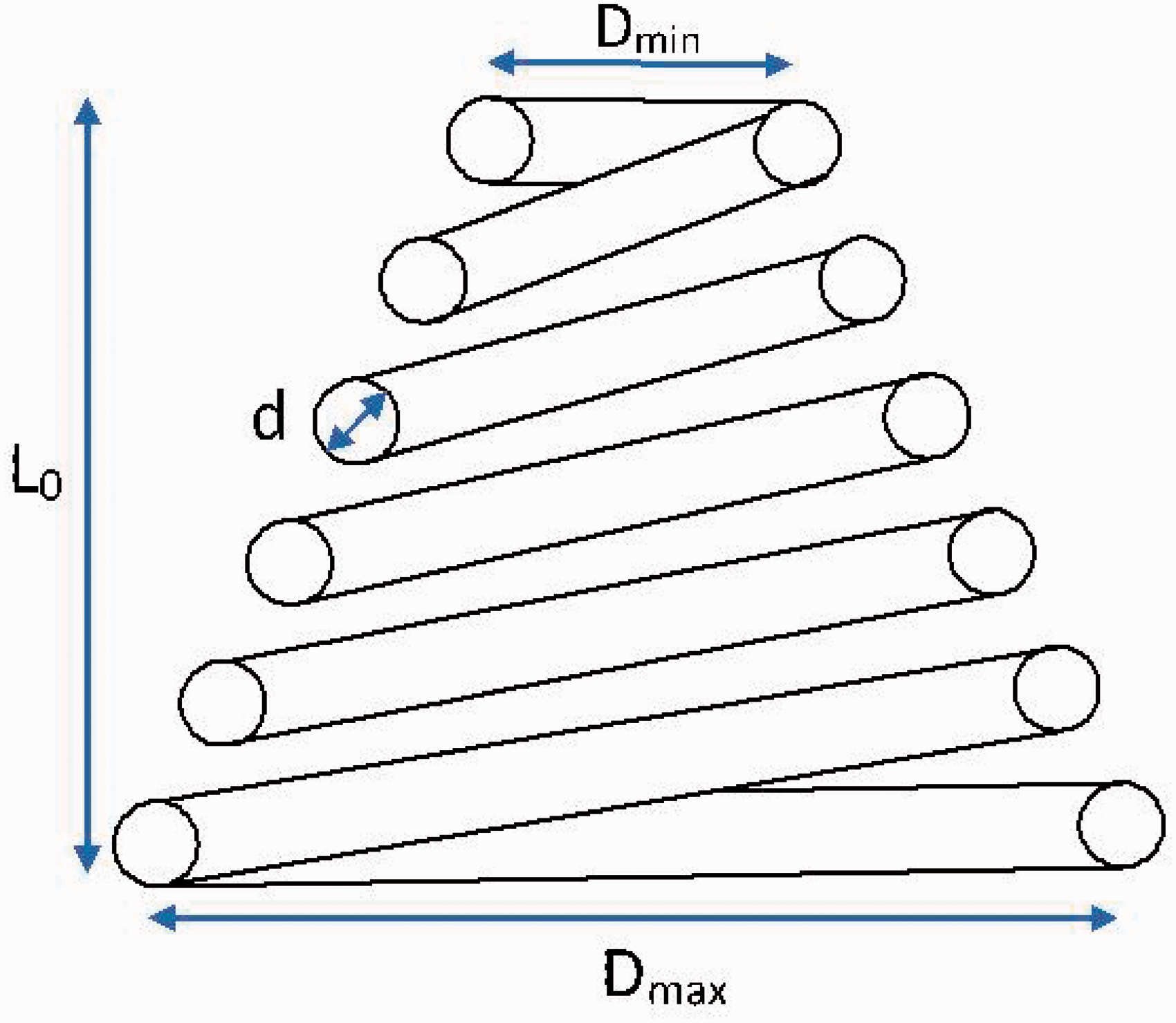
Schematic showing the conical spring dimensions.
In the linear region, where the force is below the critical force threshold (F ≤ Fc), the spring deflection is given by:

In the non-linear regime of spring operation i.e. above the critical force threshold (F > Fc):


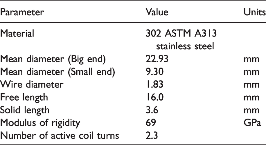
As a result of the above calculations to select conical springs with the desired nonlinear force-deflection profile, off-the-shelf conical springs were purchased for testing. Table 3 gives a summary of the physical properties of the springs used. The force-deflection profile of the springs was experimentally measured using an Instron tensile and compression testing machine (comprising a movable crosshead with 1 kN load cell attached). The crosshead moves vertically at a rate of 3 mm/min, compressing the spring quasi-statically.
Properties of the springs used in the physical prototype.
Physical prototype design and experimental setup
The energy harvester prototype is mounted midway along a rotating shaft, which is representative of real-world propulsion applications. Figure 6 shows an exploded view of the energy harvester prototype (which accommodates the determined properties of the harvester model of Figure 1, following numerical simulations of equation (6)) with the main components labelled. Describing from left to right, two stator fins are mounted rigidly on the rotating shaft, such that they are following the shaft’s motion. Two pairs of conical springs (with non-linear stiffness characteristics as described in a later section) are welded between the stator fins. The rotor fins are sandwiched between the conical springs and are mounted in the back of the rotor with small screws through a slot. N42 grade Neodymium magnets (with dimensions 20 × 10 × 5 mm) are fitted into recesses in the rotor and are joined with the steel fins by magnetic attraction. Each magnet has opposing polarity to the one directly adjacent to it so that as the rotor rotates, the flux flowing through the coil alternates between North and South and the net flux through the coil is zero when the rotor is in its neutral position.
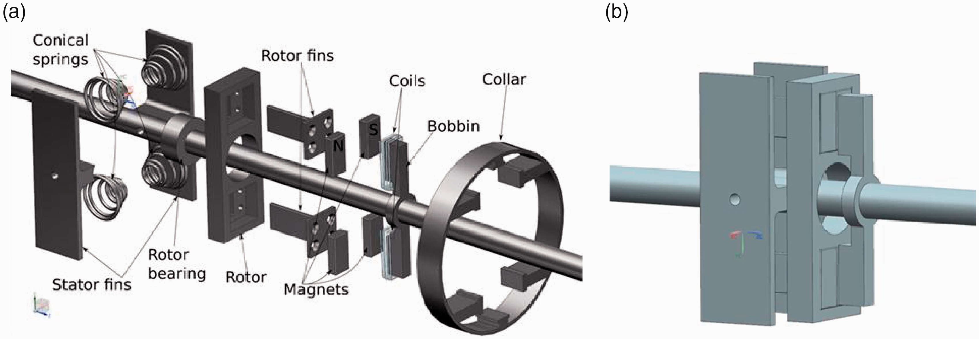
(a) Exploded view of the energy harvester prototype and (b) Fully assembled energy harvester.
In front of the magnets, a coil of copper wire is wound around an aluminium core with 48 turns in each winding. The coil bobbin is rigidly mounted to the shaft at a predefined distance from the rotor. Coils of wire are wrapped around protrusions in the plane of the magnet surfaces. The energy harvester uses a coil with non-ferromagnetic core material (in this case, aluminium) to eliminate magnetic attraction and hysteresis losses. Eddy current losses may still have a small effect on the harvester’s performance, but aluminium was preferred compared to plastic due to its strength. The prototype is utilising magnetic flux in the direction of the axis of rotation (for the convenience of manufacturing). The rotor is made of aluminium to prevent the magnetic forces affecting its motion. The fully assembled device measures 37 × 54 × 83 mm and has a swept volume of 235 cm3. The mass moment of inertia of the rotor is 9.585·10−5 kgm2.
The energy harvester is mounted on a rotating shaft with the stator fins rigidly bolted on the shaft. An electric motor is driving the shaft through a universal joint at angular orientation, as shown in Figure 7. As a result of the induced angle, when the motor rotates at a constant speed, the universal joint invokes torsional speed fluctuations in the output shaft of the form:
31

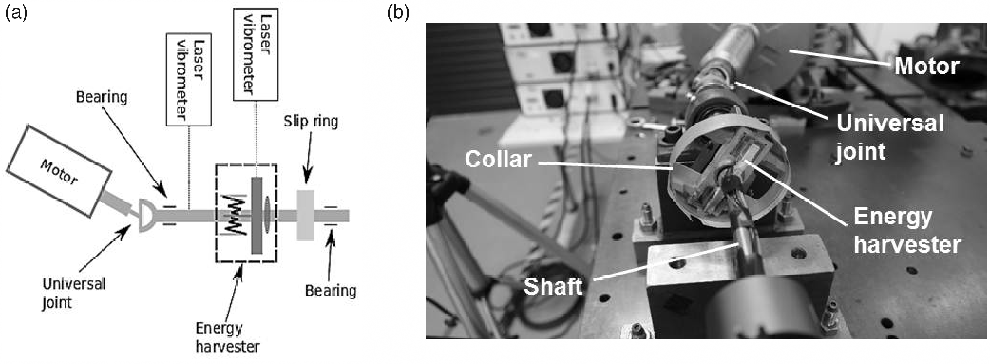
(a) Schematic and (b) front view of the experimental setup.
Where 
The above shaft speed variation resembles operating conditions met in propulsion systems. The electric motor has sufficiently high inertia and power capability (maximum 11 kW and 0.06543 kg·m2 inertia) so that there are no effects on the shaft motion due to the energy harvester’s inertia (the latter is 3 orders of magnitude lower compared to the motor’s inertia). Finally, a collar made of ABS plastic with reflective tape wrapped around it is glued on the rotor to assist with laser vibrometer measurements of the rotor’s motion (as shown in Figure 7). A second laser vibrometer measurement is made on the oscillating shaft to obtain torsional speed measurements. A slip ring is employed to measure the induced emf in the coil. This allows for the measured voltage to be captured in synchronisation with the rotor velocity measurements for model validation purposes.
Results and discussion
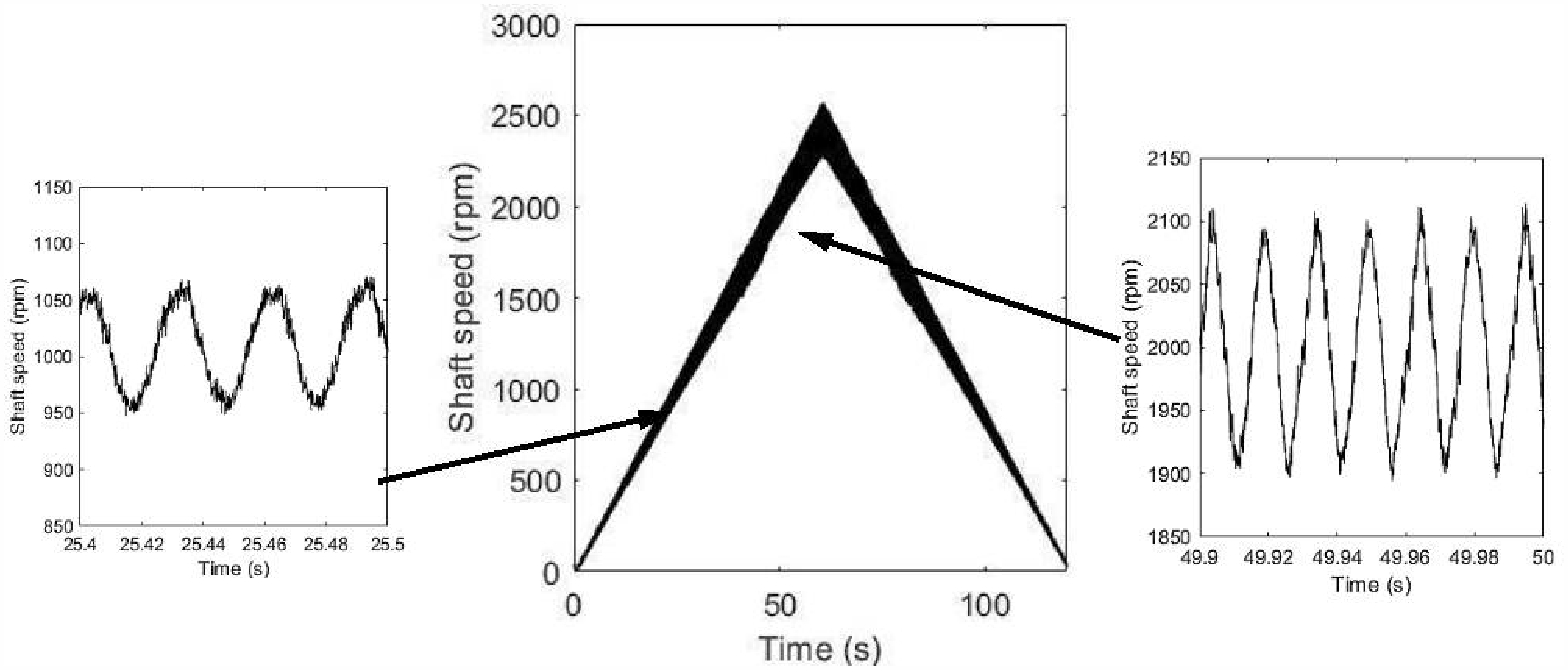
Initially the electric motor was run at 1600 rpm constant speed in order to conduct system identification. The motor was held at this speed for 30 s to allow for any transients to perish. The universal joint due to its angle orientation has introduced relatively large amplitude oscillations in the energy harvester. Figure 8 shows the measured time histories of the shaft and rotor rotational speed. The latter clearly experiences significantly greater oscillations than the former. The frequency of the shaft oscillations matches the second harmonic of the motor output rotational speed due to the universal joint arrangement. These data are then used to identify experimentally the stiffness and damping properties of the energy harvester. The restoring force surface method
32
(utilising the experimentally obtained energy harvester motion and shaft excitation) was used to calculate the stiffness and damping characteristics of the harvester. Employing the measured rotational velocities, the relative displacement between stator and rotor was calculated using the trapezium rule followed by data detrending. The relative acceleration and the shaft acceleration were calculated using the central difference method. Using the rotor mass moment of inertia, the relative acceleration and the shaft acceleration, the inertia torque on the rotor can be found as
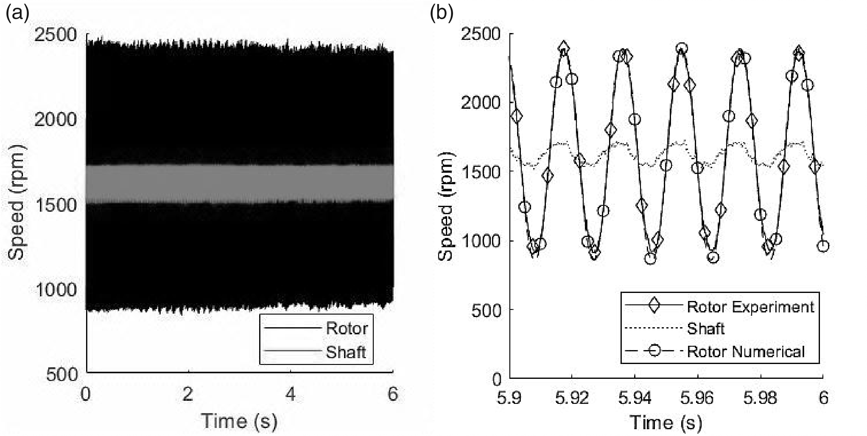
Experimentally obtained shaft and rotor speed time histories (a) Full data sample and (b) Final 0.1 s of data plotted against the numerical model results using the experimentally obtained stiffness and damping values.
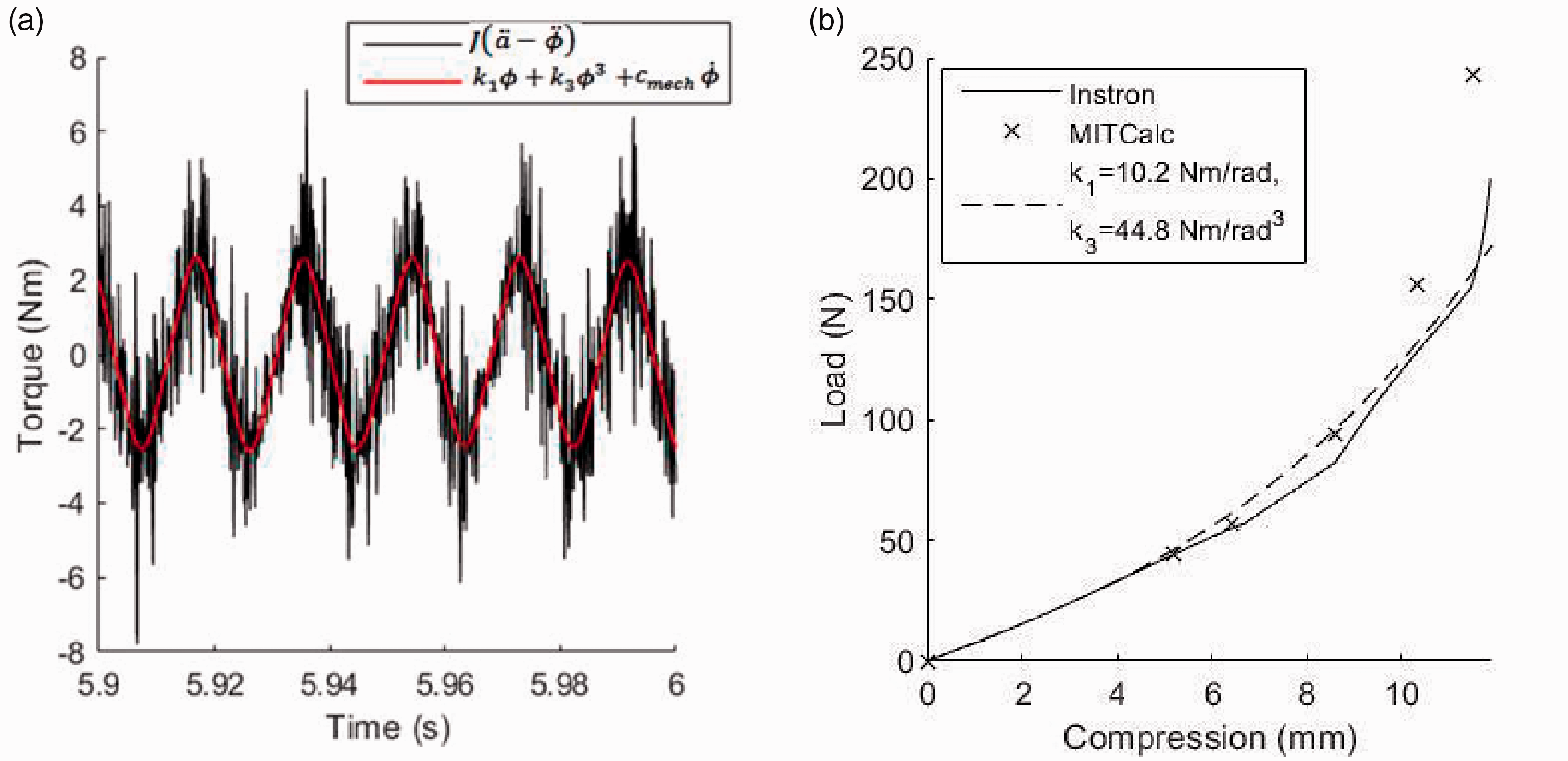
(a) Experimentally obtained inertia and spring and damping torque time histories (dynamics) and (b) Comparison of force-deflection curves obtained by the Instron compression testing, calculated analytically (MitCalc) and using the experimentally identified stiffness properties k1 = 10.2 Nm/rad and k3 = 44.8 Nm/rad3.
Results of the system identification at 1600 rpm motor speed.
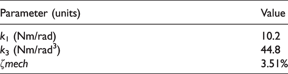
Figure 9(b) shows a comparison of the force-deflection profiles of the conical spring obtained analytically (MitCalc) and experimentally (by the quasi-static Instron compression testing and using the stiffness coefficients obtained with the restoring force surface method). The values of the stiffness coefficients have torsional spring units, having utilised the spring offset radius. There is excellent agreement within the initial linear regime. As the spring enters the nonlinear region, the Instron experiment reveals a piecewise linear behaviour. This nevertheless resembles the nonlinear hardening type spring, as shown by the dotted line which depicts the spring force using the restoring force surface method (as shown in Figure 9(a)). The same stiffness coefficients were used to plot the time history of the rotor, as shown in Figure 8(b).
The energy harvester has also been tested using speed sweeps of the electric motor. As shown in Figure 10, the motor was accelerated linearly from rest to 2500 rpm in 60 s, and it was then brought back to rest over a further 60 s with the same deceleration slope. It can be seen that the shaft speed fluctuation amplitude increases with shaft speed, as expected. Figure 11 shows the relative velocity
Shaft speed time history during a speed sweep test.
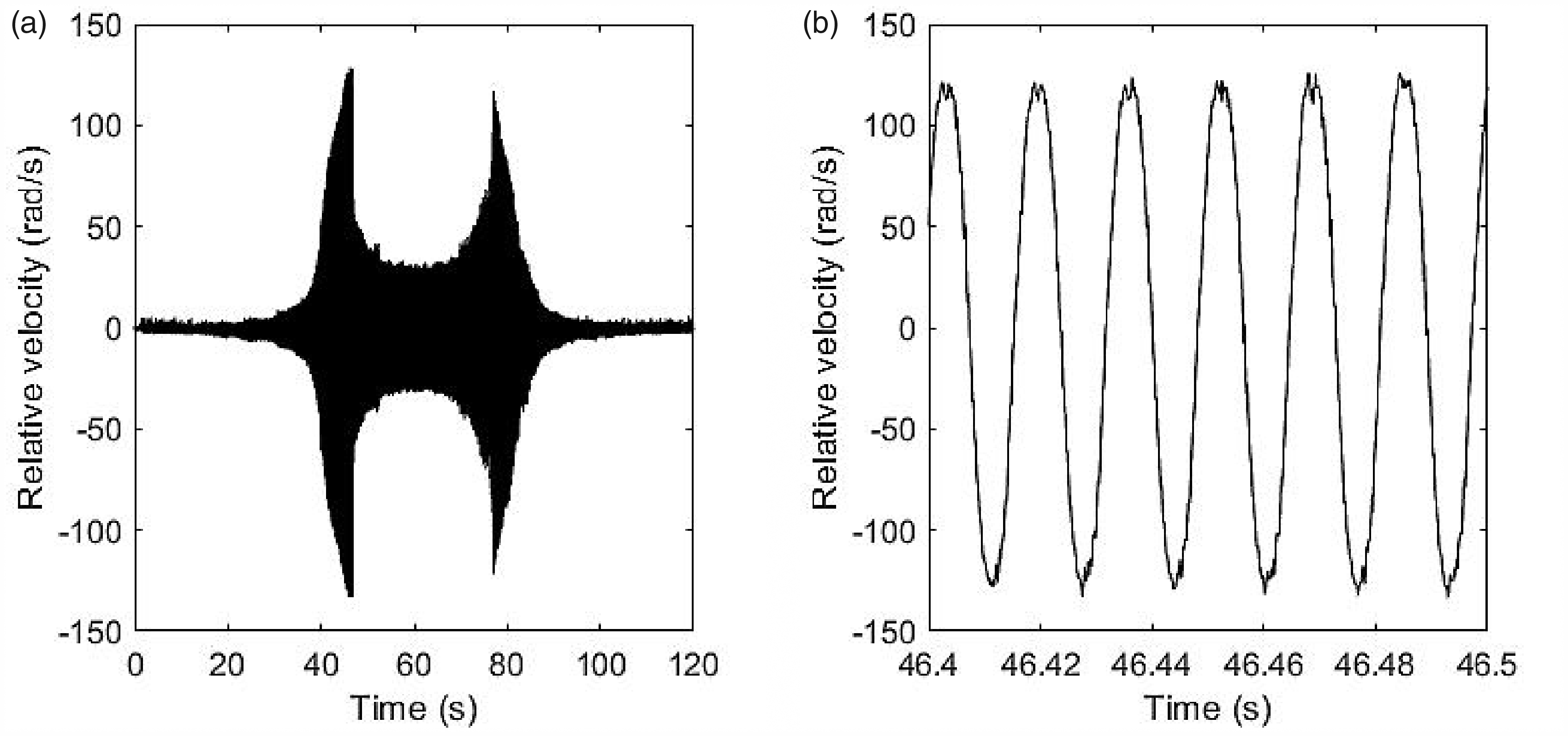
Figure 12 shows more clearly the behaviour of the energy harvester with respect to shaft speed near resonance. Figure 12(a) and (b) show the data obtained when increasing and decreasing the shaft speed, respectively. In each figure the experimental results are compared to the numerical model predictions. The response is clearly nonlinear with the accelerating speed sweep drop-down occurring at around 1870 rpm, whereas the jump-up of the decelerating speed sweep occurs at about 1770 rpm. The experimentally measured shaft speed was differentiated to obtain the shaft acceleration,
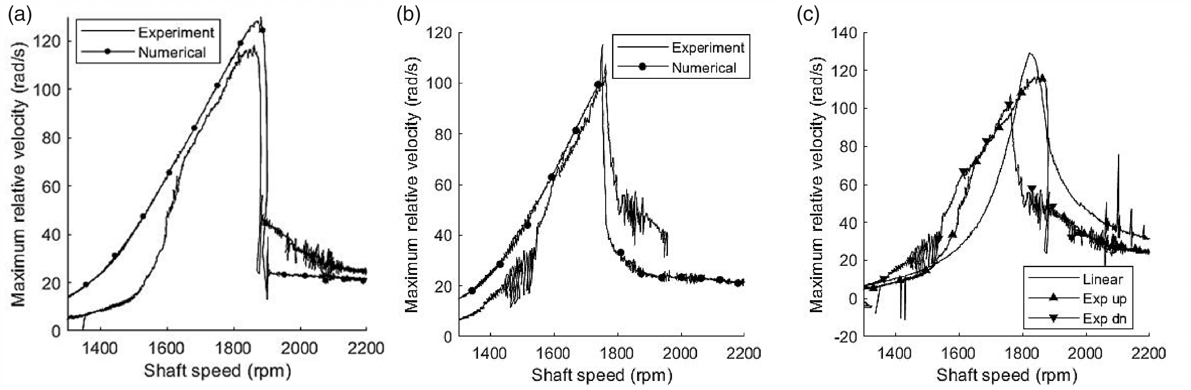
Energy harvester frequency-response plots (a) Accelerating shaft speed, (b) Decelerating shaft speed and (c) Experimental results versus numerical simulation of a linear equivalent harvester.
The stiffness and damping properties used in the numerical model are those of Table 4. The results of the numerical simulation are presented in Figure 12 against the experimental measurements. The numerical results show a drop-down frequency at about 1890 rpm (1% higher than the experimental result) and a jump-up frequency around 1760 rpm (0.5% lower than the experimental result). At lower shaft speed range (i.e. below 1600 rpm) the numerical results deviate due to the springs’ linear behaviour in that region. Between 1600 rpm and the jump-down frequency (1870 rpm), the numerical model follows the experimental results to within 10% throughout this range.
Numerical results obtained from an energy harvester with linear stiffness coefficient k = 13.6 Nm/rad (in order to achieve resonance at 1800 rpm) and the same damping ratio are presented in Figure 12(c). The comparison between the performance of the linear and nonlinear energy harvesters shows that the latter has potential for broader bandwidth, which is promising for use in applications where the shaft speed drifts accordingly (the latter effect cannot be followed by the linear harvester). It should be also noted that the effect of the duffing oscillator nonlinearity is expected to manifest itself in a more pronounced manner when the kinematic excitation in the shaft is more aggressive33 (e.g. the shaft excitation profile presented in Figure 8(b) is quite modest compared to modern automotive propulsion systems, where hundreds of rpm peak-to-peak oscillatory amplitudes are noted during normal operating conditions).
During the speed sweep tests, the voltage generated by the open-circuit coils was measured (along with the speed of the shaft and rotor). From equation (13) it can be noted that at any time instant the coupling factor can be found by dividing the generated voltage with the relative velocity. The coupling factor can be plotted against the corresponding relative displacement,
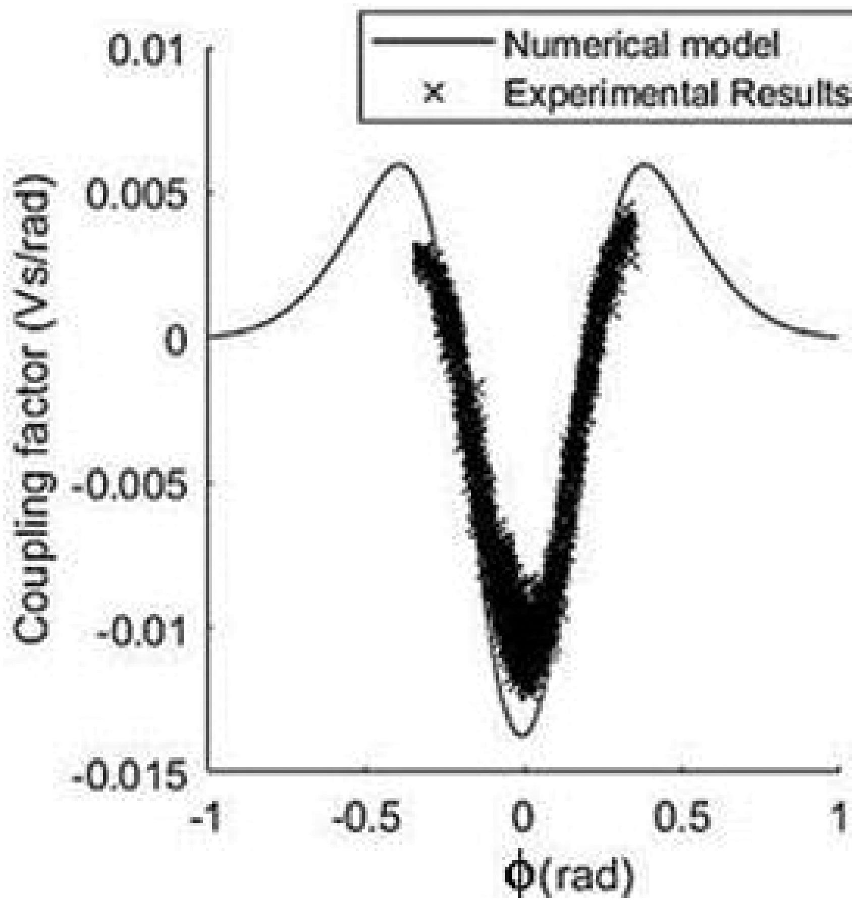
Coupling factor comparison obtained numerically and experimentally.
By taking the coupling factor as
Figure 14 shows the rms power across the load resistor that has been predicted by the nonlinear energy harvester model using the numerically calculated coupling factor and the experimentally measured coil internal resistance (5 Ohms). Results are also obtained using a linear energy harvester model with stiffness coefficient tuned so that the peak power (resonance) is generated around 1800 rpm. All other parameters are the same as in the nonlinear energy harvester. The electrical load resistance was assumed equal to the internal resistance. As can be seen, the predicted rms power is in the order of tens of mW, which is promising for effective data capture and wireless transmission energy requirements. More importantly, the shaft speed range, where the rms power produced by the nonlinear energy harvester is above 10mW, extends from about 1500 to 1900 rpm.
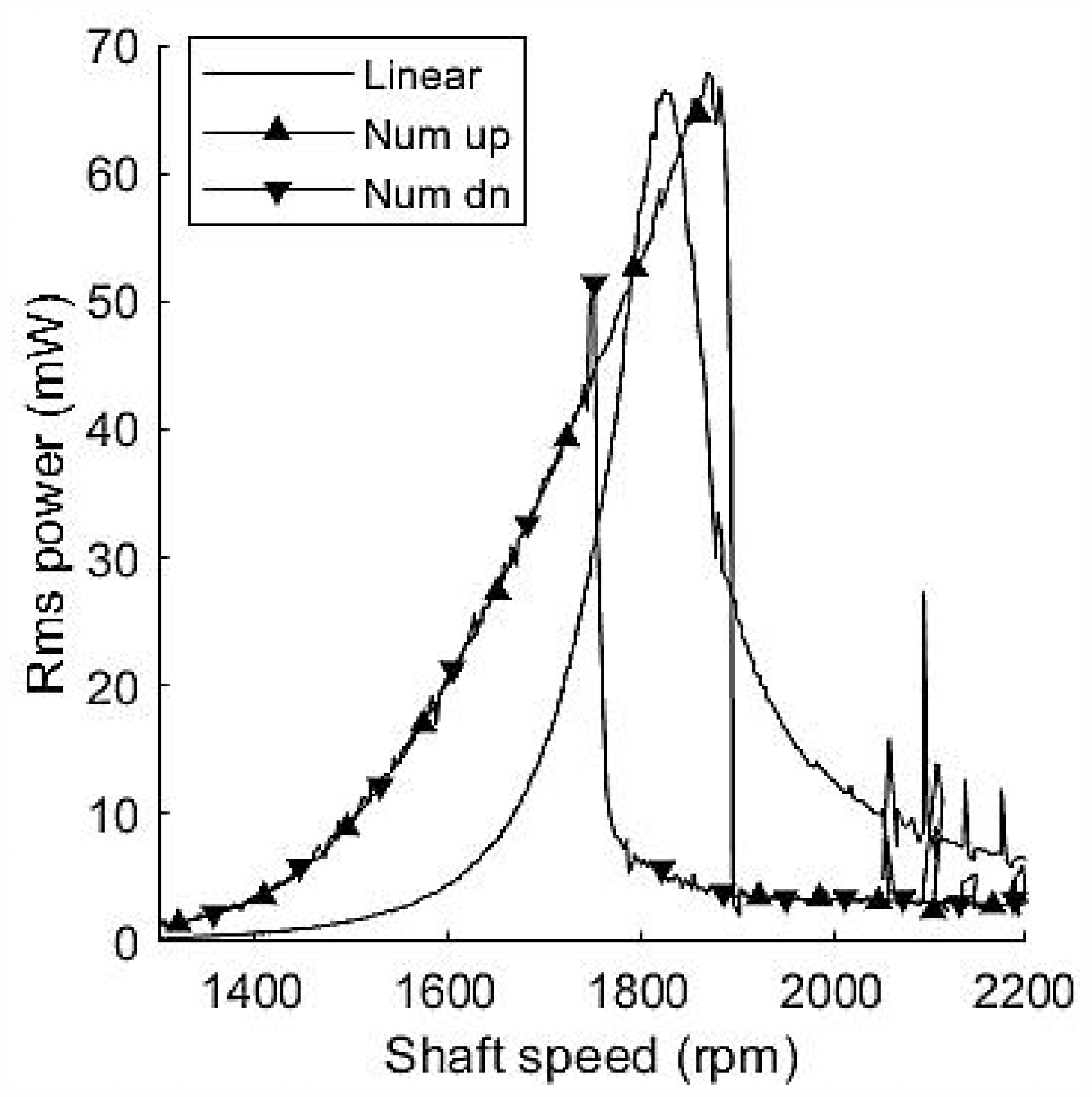
Frequency-rms power in the load resistor (nonlinear versus linear energy harvester).
Although the linear design (for the same given damping coefficient as the nonlinear harvester) has reached its performance limits, the nonlinear harvester has the potential to perform even better for the following reasons: i) the stiffness characteristics of the developed prototype are suboptimal, since readily available off-the-shelf springs had to be used (hence the desired stiffness characteristics that resulted from the numerical simulations could not be fully achieved), ii) the coupling factor was limited by the available coil winding capabilities and iii) the effect of the cubic stiffness nonlinearity (skewed frequency-response amplitude curve at resonance with large vibration amplitudes in a broadband fashion) can be much more pronounced if the kinematic fluctuations in the shaft are more aggressive. 33
Thus, there is further opportunity for improving the harvester’s performance since the achieved properties of the physical prototype were not the result of a comprehensive optimisation process. Finally, on this occasion, the nonlinear harvester performs better compared to the linear counterpart for shaft speeds below the linear resonance, whereas for shaft speeds above the linear resonance, the linear harvester performs better. This is due to the inherent hysteresis effect of the duffing oscillator.
Finally, numerical simulation results are presented in Figure 15, which show the effect of optimising the stiffness coefficients (to k1=2.06 Nm/rad and k3=122 Nm/rad3) with all other parameters taking the values presented in Tables 1 and 4. The dashed line in the figure represents the potential power generation at each shaft speed, which occurs when the energy harvester is continuously at (linear) resonance.25,27 This (optimum) power is calculated in the same way as for a typical linear energy harvester with the addition that the stiffness coefficient varies with shaft speed to ensure resonance conditions are maintained. As expected, the power generation increases considerably with shaft speed due to the encountered resonance conditions. The Duffing-type energy harvester stays within 20% of the optimum power generation throughout the speed range from 500 to 2400 rpm. This compares favourably to the linear energy harvester case (also depicted in the figure), which generates negligible power below around 2000 rpm. Nevertheless, it has to be noted that maximum power generation occurs when the electrical damping is equal to the mechanical damping of the system. 27 Currently, the electrical damping ratio is approximately 0.016%, which is less than 1% of the mechanical damping measured in the tested prototype. To address this apparent mismatch, a full optimisation of the magnet and coil arrangement is necessary, to identify smaller magnets that could be capable of achieving higher electrical damping. A concurrent optimisation of the coupling factor and stiffness coefficients is expected to increase the generated power, leading to hardware optimum performance.
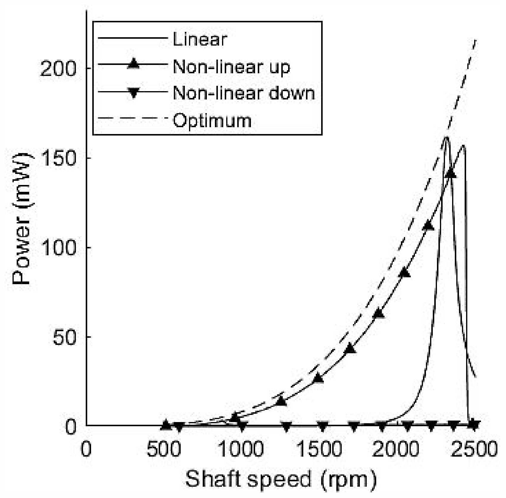
Optimised stiffness coefficients to achieve maximum bandwidth for present energy harvester.
Conclusions and future work
The physical prototype of a nonlinear energy harvester for torsional applications has been presented in this work. The prototype validates the energy harvester concept that has been presented in a previously published work of the authors. The harvester has Duffing-type nonlinear spring stiffness and is extracting energy from the torsional oscillations of a rotating shaft. The testing has been conducted in an experimental rig driven by an electric motor, where speed fluctuations were introduced through a universal joint with angular orientation. The motor was run at accelerating/decelerating speed sweeps. The three-dimensional model used to calculate the electromechanical coupling factor as a function of the rotor angular displacement has given accurate predictions throughout much of the rotor’s range of motion. The restoring force surface method has been used to determine experimentally the stiffness and damping properties of the harvester and the results were validated experimentally against compression testing of the springs. The energy harvester prototype has shown very good agreement with the results of the numerical simulations and it is performing effectively through a broad operating shaft speed range of approximately 400 rpm (since the preliminary targeted output power has been 10mW for a speed range of a few hundred rpm of shaft rotating speed). As future work, an optimisation study may improve the design features of the prototype so that the energy harvester passively follows large amplitude oscillations across the full operating range of the shaft. The energy harvester will also be connected to a sensor and a micro-controller in order to complete the design requirements of self-powered sensing for rotational applications.
Footnotes
Acknowledgements
The authors would like to express their gratitude to Wolfson School of Mechanical, Electrical and Manufacturing Engineering for its financial support under which this research was conducted.
Declaration of conflicting interests
The author(s) declared no potential conflicts of interest with respect to the research, authorship, and/or publication of this article.
Funding
The author(s) received no financial support for the research, authorship, and/or publication of this article.