
Abstract
Hybrid mobile robots with multiple locomotion modes are getting more and more popular in search and rescue (SAR) and explosive object disposal (EOD) missions because of their good terrain adaptability. Present researchers devote themselves to develop efficient and reliable transition method between different locomotion modes to make the hybrid robot more compact and flexible. In this paper, we present a novel transition mechanism for a hybrid wheel-track based on foldable rims. The wheel rim is cut into four segments so that it is foldable. And the transition between wheel and track is achieved by the folding or unfolding of the foldable rim. According to its geometrical property during the transition process, a single-freedom supporting spoke is proposed to drive the foldable rim’s transformation. We analyze the length and angle varying principles of the supporting spoke by utilizing the kinematic mode based on screw theory. According to above results, five different kinds of transition mechanism of the supporting spoke is designed, performance comparison among which is conducted by dynamic simulations. Two of the five candidate transition mechanisms are picked up for their smaller driving force requirements. Their 3D printing prototypes are also fabricated and experiments show that the hybrid wheel-track can switch between wheel and track successfully. Compared to most hybrid robots which have separate wheels, tracks and legs, this transition mechanism makes the robot own both compact structure and multimodal locomotion.
Keywords
Introduction
In recent years, small mobile robots conduct a good performance for some special tasks such as disaster rescue, anti-terrorism, intelligence recon, etc. These kinds of SAR and EOD missions are usually dangerous and narrow for a person to fulfill.1–3 Using robots to replace human brings many benefits, which can not only reduce injury and death but also save precious time. Working in unconstructed and unpredictable fields, the robots are supposed to have high speed and excellent terrain adaptability.
As to traditional mobile robots, wheels, tracks and legs are three kinds of the most commonly used locomotion mechanism. Each of them has their own advantages and disadvantages:4–7 wheel robots can run fast and efficiently on even roads while their obstacle climbing ability is quite poor; track robots can adapt to soft and wet terrains well but the speed and efficiency are rather low; leg robots have superior over-obstacle property but are complex in design and control. Obviously, traditional mobile robots with singular motion mechanism cannot reach the above-mentioned requirements.
To solve this problem, various types of hybrid robots with multi locomotion modes have been presented as an improvement because of their better terrain adaptability. These robots can choose the most effective locomotion mode in real time according to the variation of terrains: wheel mode on flat grounds, track mode on swampy terrains and leg mode for rugged roads.
A typical method to achieve the integrated hybrid of different locomotion mechanisms is segmenting or softening the wheel rim and making it transformable. This series of robots can switch between round wheel on flat grounds and wheeled leg on rough terrains by converting the configuration of the wheel rim. For example, a deformable wheeled robot utilizes a flexible rim made by paper and film.8,9 Transformation from wheel to leg is achieved by shape change of the wheel rim between round and ellipse, which is controlled by a novel spoke actuated by SMA. A claw-wheel hybrid transformable robot separates a round wheel (i.e. wheel mode) into two “S”-shaped claws (i.e. claw mode) for stairs climbing. 10 The switch of different modes is conducted by folding and unfolding the body of the robot. A walking wheel robot presented in Yao et al. 11 transforms from round wheel to legged wheel by enlarging the wheel diameter. A robot introduced in She et al. 12 switches from a circled wheel configuration to a spoke-leg configuration by the slides of crank linkages in axial direction. Another novel wheel-leg robot in Tadakuma et al. 13 can change a circled wheel to a three-jointed long leg by separating the rim into three segments and jointing them, and the transformation is achieved based on the folding or unfolding of the wheel rim. Wheel Transformer proposed in literature14,15 also cuts the wheel rim into three arc segments. The difference is that its round wheel transforms into a three-leg wheel. Quattroped and TurboQuad switch their locomotion mode by folding the morphology of circle wheels into semi-circle legs.16–19
Another category of hybrid robots is wheel-track robot that can switch between wheel and track. For example, a wheel-track transformation robot has stretchable rubber belts wrapping its two big wheels. 20 Track wheels folded in the biggish wheels can stretch the belt out to work as a caterpillar band in track mode. But the stretchable belt is easy to slip off. To improve this design, another two solutions are proposed: one of them folds the length-fixed caterpillar belt inside the robot wheel and expands it out to contact with the floor in track mode; 21 the other robot presented in Qu and Zhong 22 utilizes a diameter-variable driving wheel to adapt to the length change of caterpillar band during transformation. The caterpillar bands of these two robots both have a fixed length, which reduces the possibility of slipping off but is at the expense of a simple structure.
For the purpose of simplifying the design and combining the benefits of wheel-leg robots and wheel-track robots, we have proposed an integrated wheel-track-leg hybrid locomotion mechanism based on a foldable rim. Our basic concept is to cut the wheel rim into four segments and joint them end-by-end, so that the rim is foldable. By utilizing this foldable wheel rim, the morphology of robot wheels (i.e. the rim is a circular ring) can transform to tracks or legs (i.e. the rim is folded to a “∞” shaped ring). In this way, a more compact and simple structure with multiple locomotion modes can be achieved (see Figure 1) compared to traditional hybrid robots that have separate wheels, tracks and legs,23–27 which usually have redundant structure and motion interference between different locomotion mechanisms, resulting in low efficiency.
Reconfigurable wheel-track-leg hybrid robot. (a) Wheel mode. (b) Track mode. (c) Leg mode.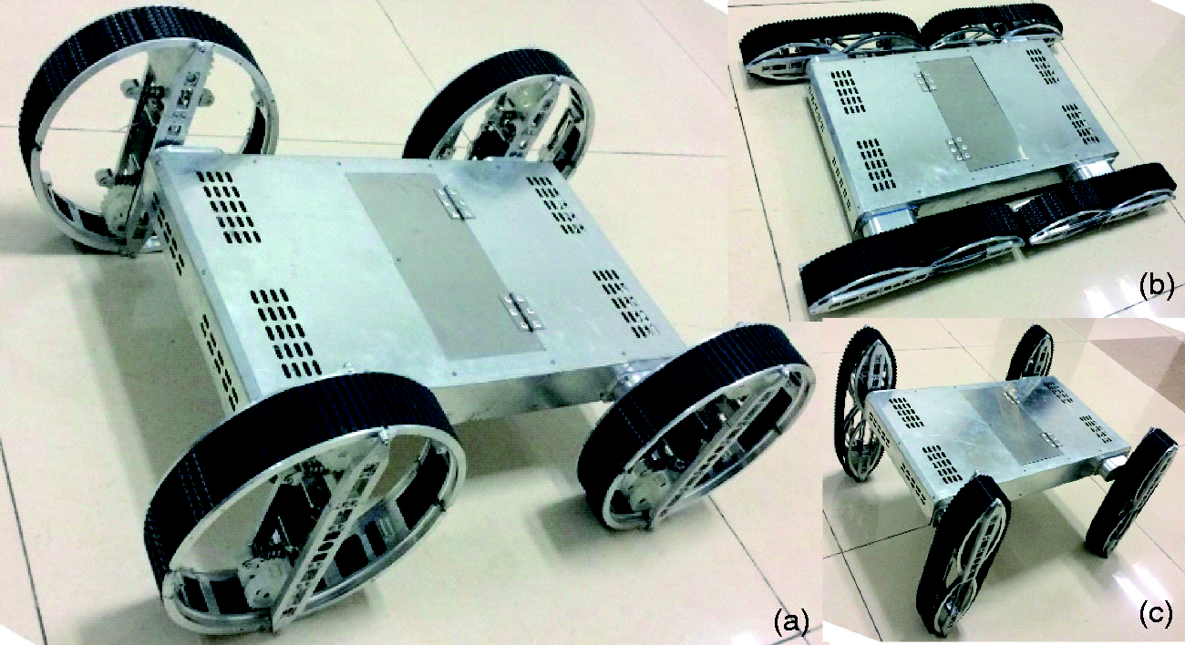
In this paper, functions of wheels, tracks, and legs are integrated into a transformable wheel by utilizing a foldable rim to change the robot-ground contact type, which can eliminate the drawbacks of the mechanism redundancy. Regarding the topologic configuration design, we establish a kinematic model of the foldable rim by utilizing the screw theory. In this way, length and angle varieties of a structure-uncertain supporting spoke that is proposed to control the foldable rim’s shape can be easily figured during the transformation. Through contrastive analysis of those variety principles of the supporting spoke with different initial position, we select several optional transformation approaches and fabricate their 3D-printed prototype respectively. At last, successful function experiments verify the feasibility of transformation program, providing theory fundament for future structure design of the transformable wheel.
In the following, we will start with the basic concept of wheel-track-leg integration and transformation in the General design of transformable wheel section. The Kinematic modeling of fordable rim section introduces the kinematic modeling process based on the screw theory. Then, length and angle varies principles of the supporting spoke during transforming are analyzed in the Transformation property analysis section. The Experiment results section reports a comparative experiment of several candidate configuration options of the transformable wheel. Finally, the Conclusion and future works section makes a summary to the whole paper.
General design of transformable wheel
Conceptual design
The basic concept of this paper is to develop a compact wheel-track-leg hybrid robot based on an integrated transformable mechanism which can switch from a wheel to a track or a leg, instead of to simply assemble separate wheels, tracks or legs together. How can three different locomotion mechanisms be merged together? As shown in Figure 2(a), supposing a hybrid locomotion mechanism is composed of several parts: common part, which is used in all the modes of wheel, track and leg; special part, which is only used in one or two modes; switch mechanism, which conducts transformations among different modes. It is easy to understand that the bigger common part is, the smaller special parts will be and the simpler and more compact structure the hybrid locomotion mechanism will have. Then the job is to make the common part as bigger as possible. We can start with the similarities and differences among wheel, track and leg.
Design concept of transformable wheel. (a) Concept of merging-hybrid. (b) Concept of mode-switch.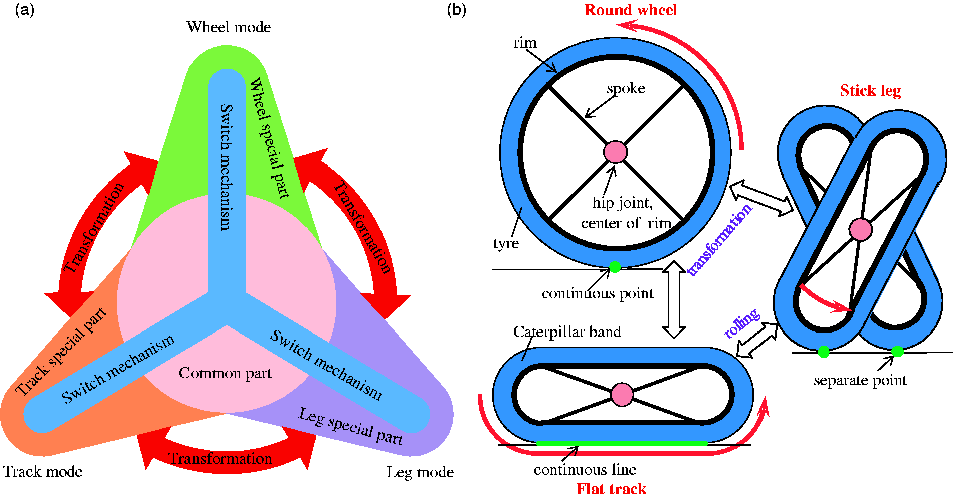
Generally, a wheel consists of a round rim and a set numbers of supporting spokes radiating from a rotational axis which is located at the center of the rim. Usually there is a rubber tire that wraps the wheel rim to enhance friction with the ground. A track is composed of track wheels which are mounted on a wheel frame with a caterpillar band surrounding them. A leg has some joints and links to make itself move flexibly.
In spite of configuration differences on geometry, the ultimate diversity of wheel, track and leg originates from their contact forms against the ground. That is, as shown in Figure 2(b), a wheel contacts the ground with continuous points while a track with continuous line and a leg with separate points. Supposing that the circular rim is squished into a waist-shaped ring, the round wheel switches to a flat track. Furthermore, when rotating to stand up, the flat track becomes a rolling leg.
In this way, transformation among wheel, track and leg is achieved by the deformation of wheel rim. As the key component, the multimodal hybrid robot switches among different locomotion modes based on the conversion of the transformable wheel. Detailed design is presented in this section.
Configuration design
Two choices are available to make the wheel rim deformable: one is to use soft material to make the rim flexible; the other is to segment the rim into a number of arcs to make it foldable. In this paper, we focus on the latter approach and the former will be researched in future work.
The conversion of the transformable locomotion part between the wheel mode (State-C) and the track mode or leg mode (State-F) is achieved by the unfolding and folding of the deformable rim. In State-C, the flexible rim remains circular and the track wheels are hidden inside the rim. In state-F, the rim is compressed and folded while the track wheels are extended to stretch the caterpillar band out at same time. This involves not only the linkage and coupling between different motions, but also the tolerance and interference between different structures. To make the structure suitable for the intended function, they need to meet the following requirements: (1) in State-C, the track wheels should be fully retracted inside the round rim and should not protrude outside the rim; (2) in state-F, the track wheels are supposed to stretch the caterpillar band to make it completely separated from the rim without contact; (3) in State-C, the transformable rim in folded state should be wrapped in the track ring and cannot be protruded; (4) in both State-C and state-F, as well as the transformation process, each movement cannot interfere with each other.
First of all, we need to define the configuration of transformable rim. Since foldable rim can be treated as a planar linkage mechanism, its degree of freedom (DOF) can be calculated by

Since one of the arc rims is used as frame, then there is

This means at least four arc segments are need to make the wheel rim foldable. To achieve a simplest structure, we set Topology configuration of the foldable rim. (a) State-C. (b) State-T.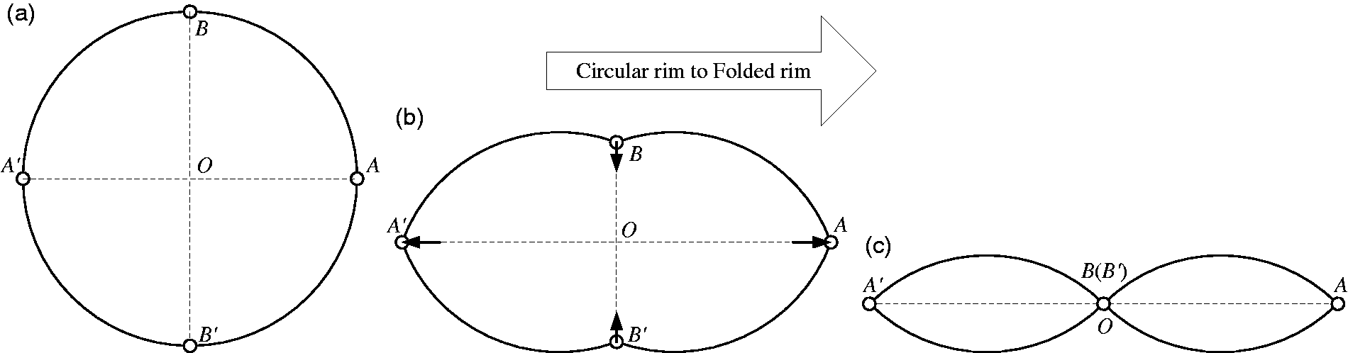

The next step is to design the track ring which is composed of track wheels and caterpillar band. According to the present research, there are three types of classical layout:
Both drive and idler wheels contact with ground, working as loading wheels as well; Only drive wheel contacts with ground and works as loading wheel as well. Idler wheel breaks away from ground with a certain distance; Neither drive nor idler wheel contacts with ground and both of them break away from ground with a certain distance.
According to above foldable rim configuration and track ring types, four kinds of transformable wheels in different configurations have been listed respectively as shown in Figure 4. Here dotted lines describe rim in State-C and solid lines describe rim in State-F.
Combined configuration of foldable rim and track wheels. (a) Both ends on-ground. (b) One end on-ground I. (c) One end on-ground II. (d) Both ends off-ground.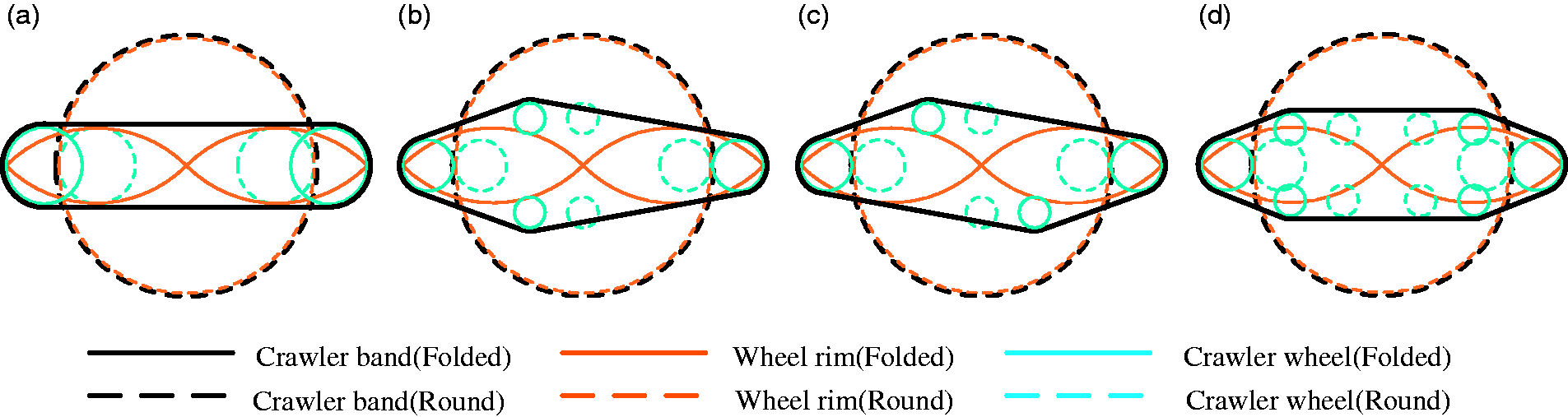
These four kinds of transformable wheel configuration can meet the above four matching requirements. In theory, they can all realize the wheel mode and track mode conversion. However, in order to get a good performance, we should choose the best one. Dynamic balance, structure simpleness and factory cost are the main factors that are taken into consideration.
Of the above four configurations that meet the requirements, (b) and (c) can be classified into the same category since they have the totally same components. The only difference between them is that the arc rims and track wheels are located in different position, which leads to no distinction in their performance. Obviously, both (d) are more complex and costly than (a), (b) and (c) because the former two have four track wheels. So we will take (a) and (b) as configuration examples of the hybrid transformable wheel in the following research.
Kinematic modeling of fordable rim
Spoke configuration
The foldable rim is a single-DOF mechanism. Only one active spoke is needed to drive its transformation (State-T). Since its length l and angle β are variables during the transformation, there are five kinds of different forms for active spoke to support the foldable rim (see Figure 5). When the foldable rim transforms from a round circle (State-C) to a “∞”-shaped ring (State-F), diameter Spoke configuration of the foldable rim. (a) State-C. (b) State-T.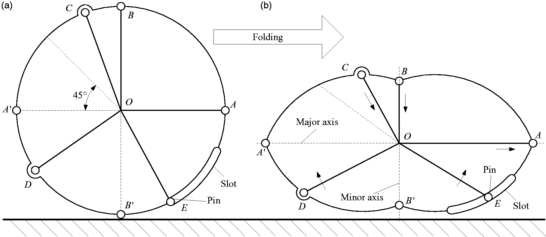
The transformation of the foldable rim is driven by the active spoke, for which its length and angle are the most important parameters. Above all the five kinds of supporting spokes, some of them only change their angles during the transformation of the foldable rim. While some of them only change their lengths, the rest of them change both angle and lengths. Our aim is to pick out the most reliable and efficient supporting spoke for the transition driving of the foldable rim. In the following paragraph, the length and angle variation properties will be studied in detail to uncover the transition principles of the supporting spoke.
Kinematic modeling
Since the foldable rim is made of four identical arc rims, it would be much simpler and will not generate errors if we choose only one of them to build kinematic mode (see Figure 6). Similarly, we take Spoke Kinematic mode of transformation process.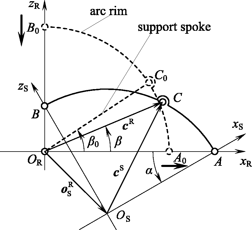
When the foldable rim switches between State-C and State-F, the transformation angle α changes in the range of
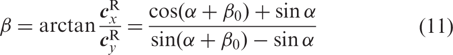
When analyzing its kinematic properties, we treat the supporting spoke as a single-DOF mechanism with unknown detailed structure. Since the foldable wheel rim motions in a plane, its kinematic principles can be described by utilizing coordinate conversion. In state-R, fixed frame
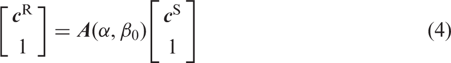
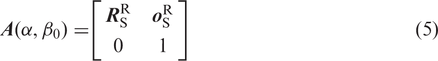
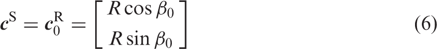
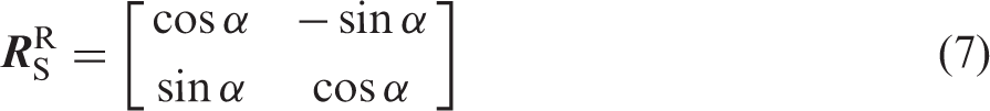
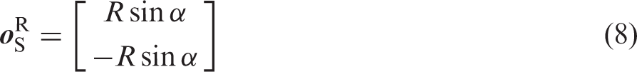
Then there is
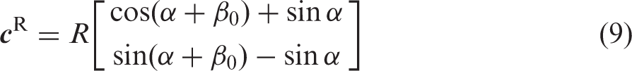
So that length
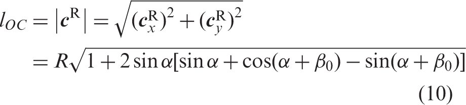
For the purpose of detailed analyzing the variation properties of the supporting spoke, the gradient function of the spoke length can be solved by partial differential of the transformation angle α
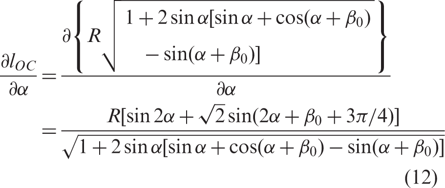
Since we only care about its variation principle rather than it numerical value, the curvature function of the spoke length is described as

When α transforms from
When
Transformation property analysis
Length varies principle
Based on formula (10), we can see that the deformation of the supporting spoke Length variation properties of supporting spoke. (a) Length variation of different initial angle. (b) Length curvature of different initial angle.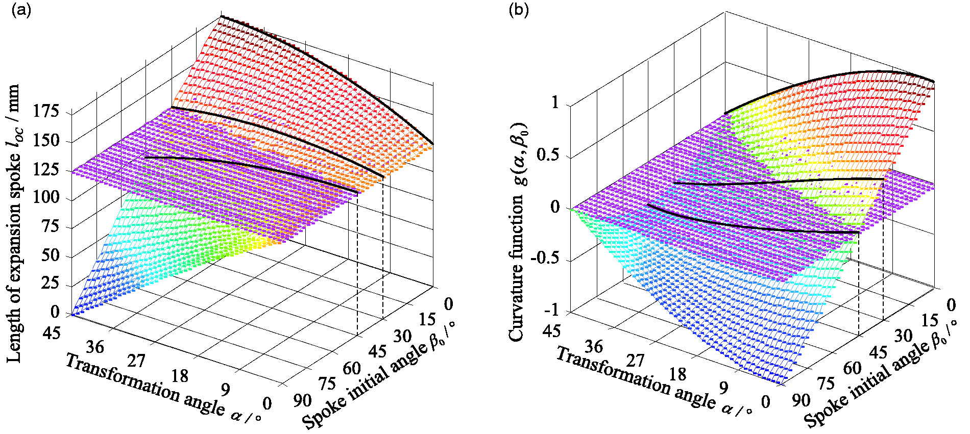
As can be seen from Figure 7, the transformation angle α changes between
Stage 1:
When
Angle varies principle
It can be seen from Figure 8 that regardless of the initial value Angle variation properties of supporting spoke.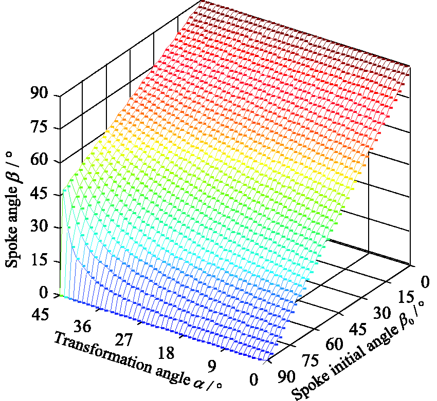
Combing length and angle variation regulars of the supporting spoke, we can summarize several design principles as follows:
For a rotating spoke, which drives the foldable rim transforming by angle rotation, it can support any position along the arc rim. In a unidirectional transition progress, the spoke rotates one-way. For forward transformation, angle α monotonically decreases while monotonically increasing when it switches back. There are two types of connection between the spoke and the rim. One is hinge connection utilized by Spoke OC, the length of which should be telescoping at the same time. The other one is pin-slot connection utilized by Spoke OD, the length of which is fixed and have a pin at the end to slide along the slot on the arc rim. For a telescoping spoke, which drives the foldable rim transforming by length telescoping, it can only support at certain area of the arc rim. That is
Experiment results
Transformation experiments
Based on above spoke configuration analysis, we propose five different spoke designs and fabricate their prototypes by 3D printing, respectively, according to the five kinds of supporting spoke configuration proposed above (Figure 9). All of them can represent three morphologies: circular rim (State-”C”), during transformation (State-”T”), and folded “∞” (State-”F”).
Five kinds of supporting spokes in different modes.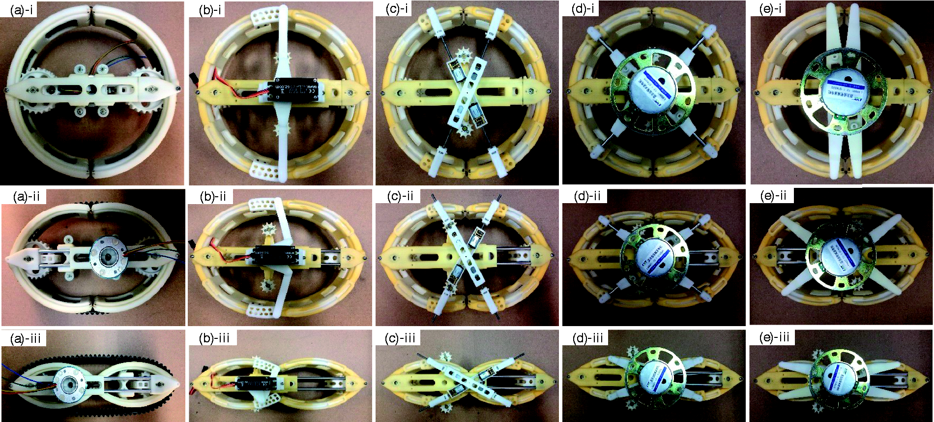
These supporting spokes can be classified into two types. One type is telescoping spoke, which drives the foldable rim transforming via length variation (Figure 9(a) to (c) correspond to Spoke OA, OB, OC, respectively). The other is rotary spoke, which drives the foldable rim transforming via angle variation (Figure 9(d) and (e) correspond to Spoke OD and OE, respectively). In each spoke prototype, i, ii, iii correspond to State-“C”, State-“T”, State-“F”, respectively. For the purpose of structure balance, supporting spokes have been designed symmetrically about the major axis in each prototype, which makes no influence to the freedom of the whole transformable wheel.
As to telescoping spokes, there are many mechanisms to achieve linear elongating and shortening motions, such as screw-nut mechanism, rack and pinion mechanism, crank-slider mechanism, etc.
As to rotary spokes, the simplest method to achieve a rotation is to mount a motor on the rotation center. Benefiting from its compact body and easy control, a steering engine is utilized for this situation.
As to Spoke OA, which only changes its length during the rim folding process, it supports at the hinge point on the major axis. A DC motor is utilized to drive a screw-nut mechanism which has a self-locking property, so that stretching motion along the major axis is achieved (see Figure 9(a)).
As to Spoke OB, it also only changes its length, supporting at the hinge point on the minor axis. Contrary to Spoke OA which monotonously elongates (from R1 to 1.4R1), Spoke OB monotonously shortens (from R1 to 0) during a forward transformation process. When in State-”F”, B and B′ are nearly coincident, which means there is no space for a screw-nut mechanism. In this case, a crank-slider mechanism is available. The crank’s rotary motion can be switched to the slider’s linear motion, which means we utilize a rotating crank to realize the length telescoping of the spoke (see Figure 9(b)).
As to Spoke OC, which also drives the foldable rim transformation by changing its length, it supports at point C on the arc rim, whose angle changes compliantly with the rim’s transformation. A screw-nut mechanism is applied to achieve the telescoping of the spoke, controlling its length variation. For structure symmetry, two identical telescoping spokes form an “X”-shaped cross (see Figure 9(c)).
As to Spoke OD, similar to Spoke OC, it also supports at one joint point D on the arc rim, forming an “X”-shaped cross. The difference is that OD controls the foldable rim’s shape by rotary motion, which is driven by a motor mounted on the joint center of the cross. At the same time, the spokes’ length changes accordingly (see Figure 9(d)).
As to Spoke OE, also a rotary spoke similar to Spoke OD, it drives the foldable rim’s transformation by its rotation. There is a slot on the arc rim, along which the pin on the spoke’ head can slide during the transformation. In this way, the spoke’s length can be kept constant while it drives the foldable rim transforming by changing angle rotation. The rotary motion is achieved by a steering engine mounted on the rotation center (see Figure 9(e)).
Performance comparison
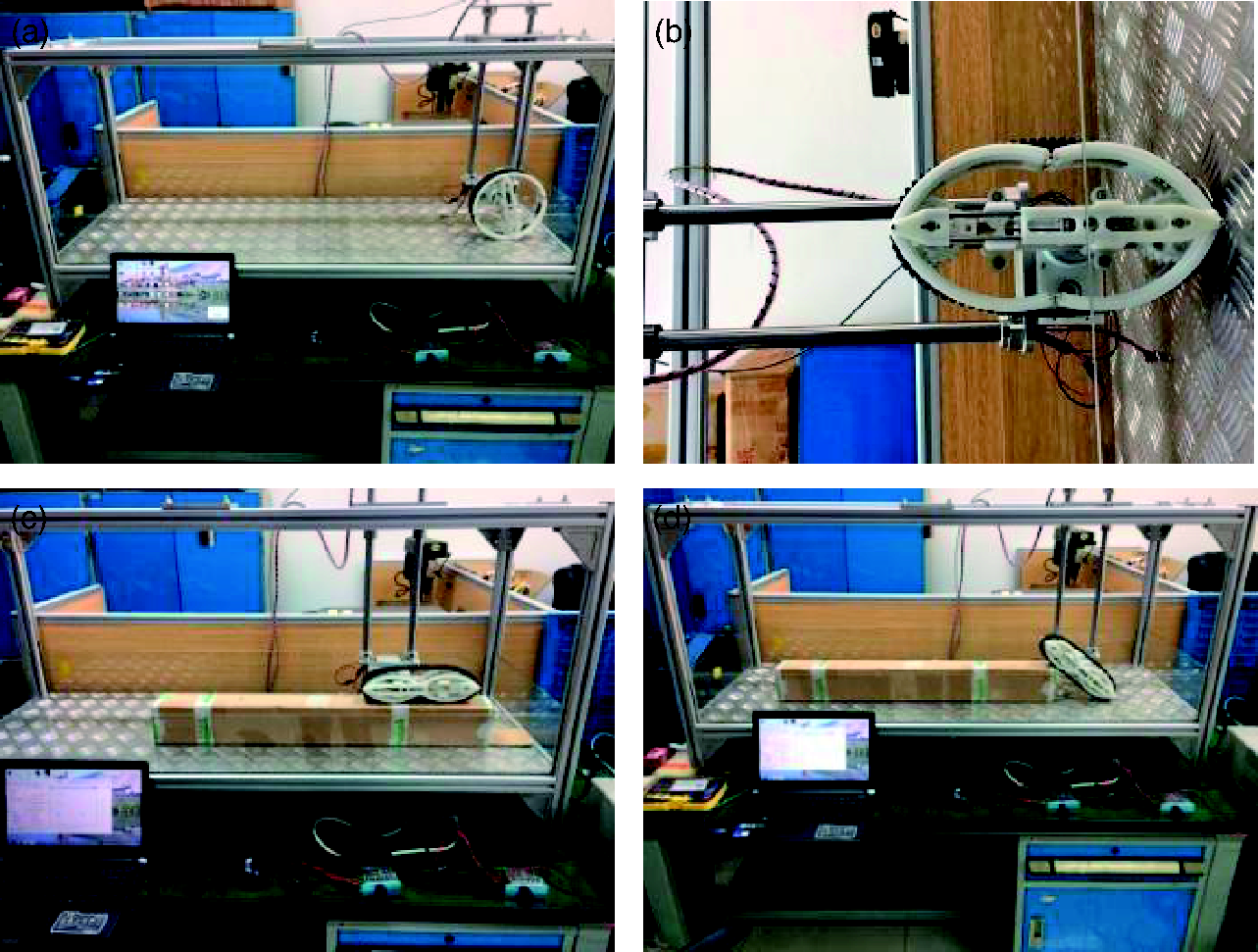
To make the transformation process easier, a gravity-assistant transformation strategy can substantially raise the transformation success rate. At the beginning of transformation from State-“C” to State-“F” (forward transformation, from Figure 10(a) to (c)), the wheel frame is in horizontal position, so that robot body goes down with the rim’s folding during the forward transformation, during which process the gravity plays a positive role and facilitates the transformation. When switching back (inverse transformation, from Figure 10(d) to (f)), the wheel frame is in vertical position and long end down, so that the robot body also goes down with the rim’s unfolding during the inverse transformation. The gravity also performs positive work and facilitates the transformation. In this way, neither of the forward and inverse transformation needs any external driving force theoretically.
Best load condition of transformation process. (a) State-C. (b) State-T. (c) State-F. (d) State-F. (e) State-T. (f) State-C.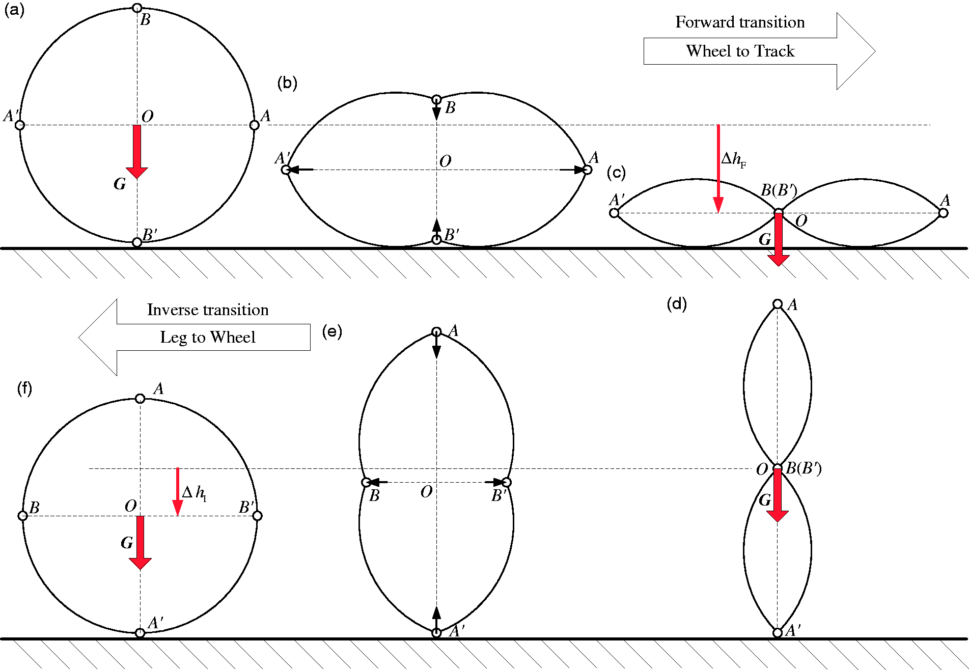
But this is only the best situation which barely happens in working environment. In wild field, we even take the worst situation into consideration, which is exactly contrary to the best situation (Figure 11). When switching from State-“C” to State-“F” (forward transformation, from Figure 11(a) to (c)), the wheel frame is in vertical position with long end down. When switching from State-“F” to State-“C” (inverse transformation, from Figure 11(d) to (f)), the wheel frame is in horizontal position, which means the gravity does negative work during both forward and inverse transformation process.
Worst load condition of transformation process. (a) State-C. (b) State-T. (c) State-F. (d) State-F. (e) State-T. (f) State-C.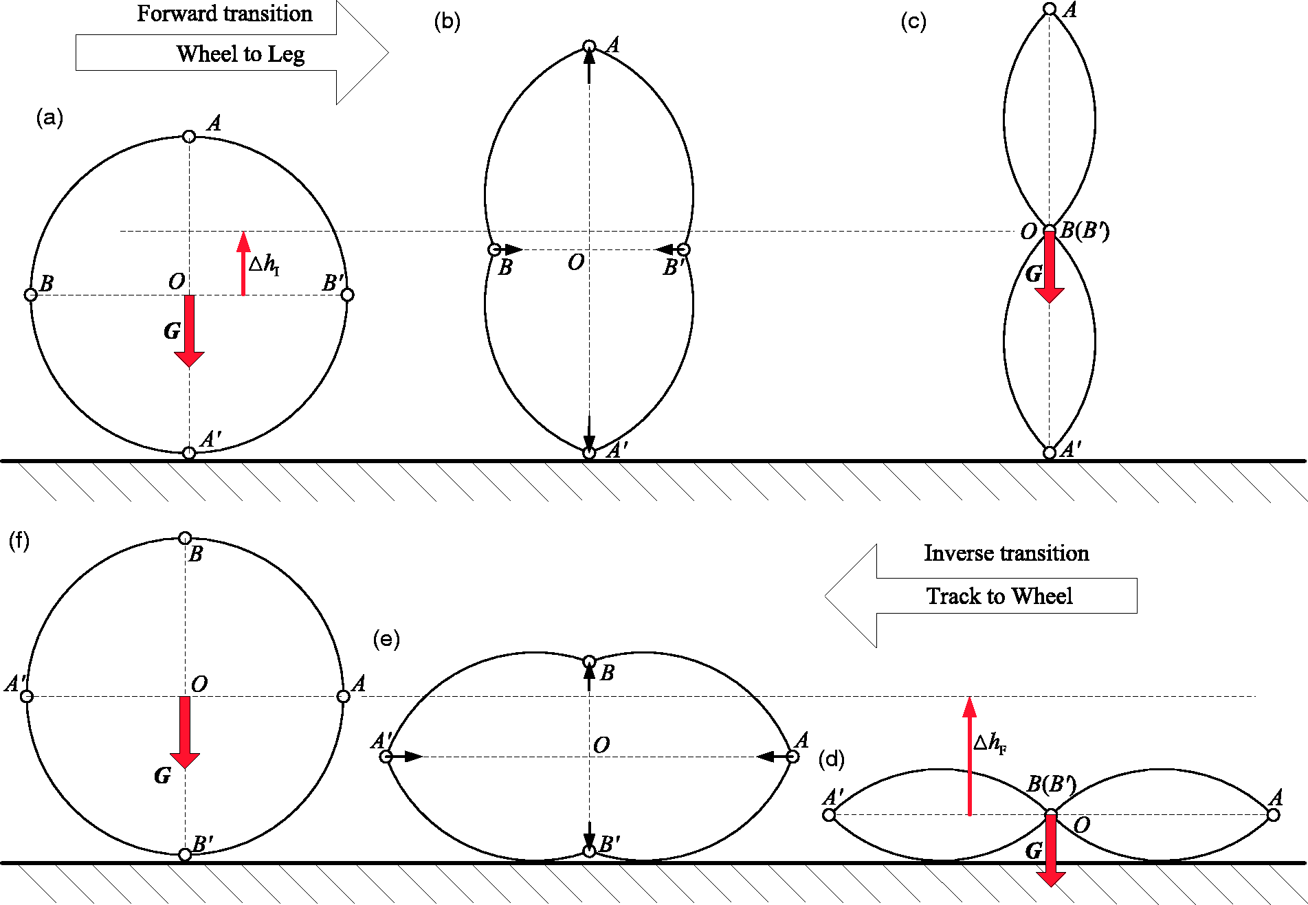
The success of transformation from a round rim into a folded rim depends on the transition driving force from the supporting spoke. A whole transformation process includes two phases: phase I is forward transformation from a round rim to a folded rim; and phase II is inverse transformation from a folded rim to a round rim. Supposing the whole robot weighs 40 kg, then each single wheel bears 10 kg. The radius of the foldable wheel rim R1 is 125 mm. Figure 12(f) shows the length change of the major axis during a whole transformation process, which elongates at phase I and shortens at phase II.
Driving forces of different kinds of supporting spokes.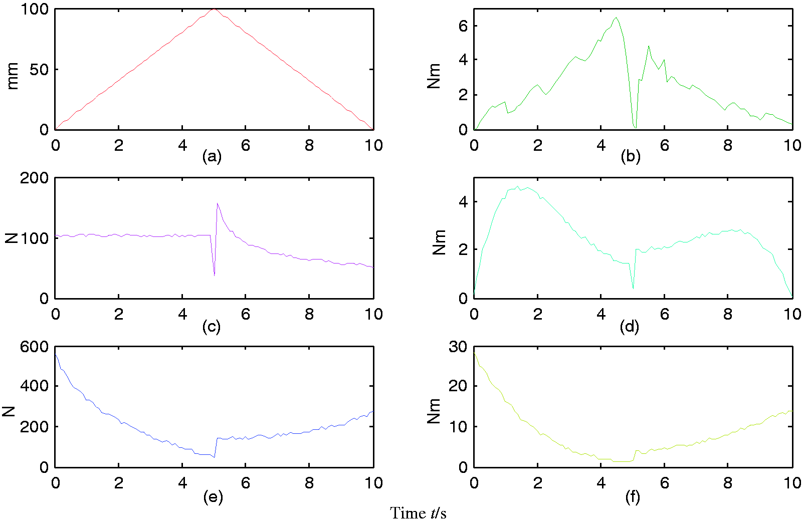
Figure 12(a) to (e), respectively, describes the driving force/torque of Spoke OA-OE as the major axis elongates/shortens at a uniform velocity 20 mm/s during a full transition process. It can be seen that among telescopic spokes, Spoke OA needs the smallest driving force. This means it has the biggest transition success rate than others in the same situation. Among all the rotary spokes, Spoke OB needs the smallest driving torque. This means it has the biggest transition success rate than others in the same situation.
It should be noted that the configuration of Spoke OB was originally designed as a telescoping spoke as shown in Figure 5. But in the structural design, a crank-rocker mechanism is used to realize the linear motion of the spoke length change, considering the spatial scale limitation as shown in Figure 11(b). That is, the telescoping spoke is realized by a rotary motion, and that is why the curve shows the driving torque as shown in Figure 12(b).
The curves trend of the Spoke OC (see Figure 12(c)) and Spoke OD (see Figure 12(d)) are similar, because both of them support on the circular rim. So their transition driving powers have the same variation principle. The difference is that the former controls the rim shape by force-driven spoke’s length telescoping, while the latter is by torque-driven spoke’s angle rotation. The curve of Spoke OE (see Figure 12(e)) looks rougher than other four spokes, because its pin-slot motion pair between the spoke and the arc rim has less motion smoothness than the other spokes with revolute joint or translational joint.
To verify the transition performance of the configuration design, we develop two transformable wheel by 3D-printing. One of them utilizes the rotating spoke with rim configuration shown in Figure 4(b) (see Figure 13), and the other utilizes the telescoping spoke with rim configuration shown in Figure 4(a) (see Figure 14).
Transformable wheel with rotating spoke. (a) Wheel mode. (b) Transformation. (c) Track mode. (d) Leg mode. Transformable wheel with telescoping spoke. (a) Wheel mode. (b) Transformation. (c) Track mode. (d) Leg mode.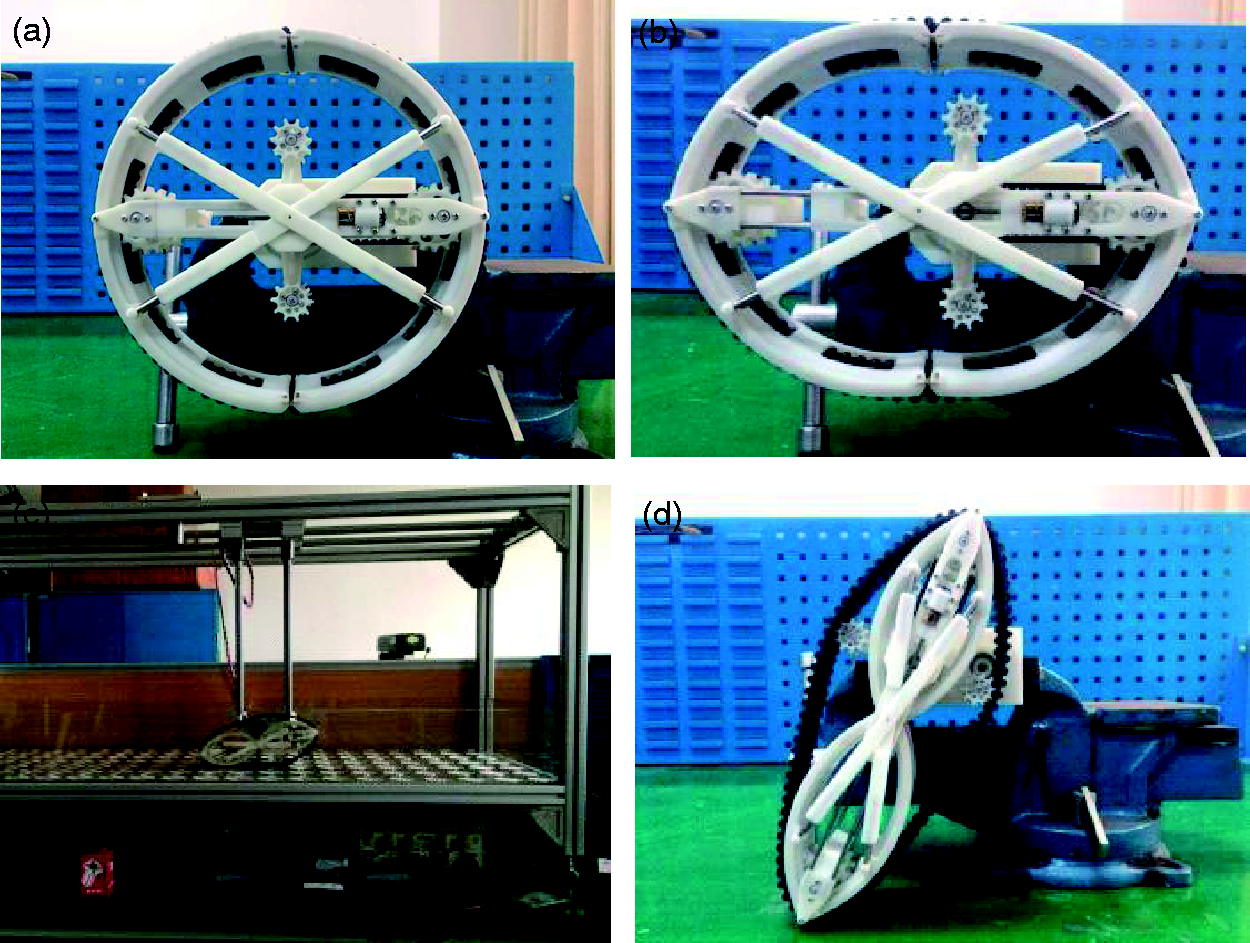
In these two prototypes, we utilize a length-fixed caterpillar, which also works as a tyre in wheel mode (see Figures 13(a) and 14(a)). Its length variation during the transition process is well controlled within the allowable range by mechanism parameters optimization. This design can reduce the drop-off possibility of the caterpillar efficiently. Each transformable wheel owns three driving motors. One motor drives the transformation of the foldable rim. The other two drive the locomotion of the transformable wheel, as a coaxial output power unit. One of the locomotion driving motors drives the whole foldable rim rotating. The transformable wheel works in wheel mode when the foldable rim is circular and leg mode when the foldable rim is folded. In track mode, the other one drives the caterpillar running via a timing belt transmission between its output shaft and the track driving wheel. The detailed design process is presented in our published paper. 28
Experiments of transition and motion between different modes are conducted. According to the experiment results, we can see that the transformable wheel with proposed transition mechanism can successfully switch between wheel, track and leg. Besides, locomotion of different modes run smoothly without interference (For video of the experiments, you can visit: http://list.youku.com/albumlist/show/id_51874021).
Conclusion and future works
The novel integrated-designed transformable wheel-track-leg hybrid robot owns multiple locomotion modes, which provide itself huge advantage in SAR and EOD missions. By utilizing a foldable wheel rim, a transformable locomotion part with compact structure can switch between wheel, track and leg. Successful shape-shift of the foldable rim is the necessary condition for multimodal transition of a robot. Our aim is to develop reliable transformation driving mechanism to make the transition success rate as high as possible. In this paper, we present a novel transition mechanism for a hybrid wheel-track based on foldable rims. The wheel rim is cut into four segments so that it is foldable. And the transition between wheel and track is achieved by the folding or unfolding of the foldable rim. According to its geometrical property during the transition process, a single-freedom supporting spoke is proposed to drive the foldable rim’s transformation. We analyze the length and angle varying principles of the supporting spoke by utilizing the kinematic mode based on screw theory. According to above results, five different kinds of transition mechanism of the supporting spoke is designed, performance comparison among which is conducted by dynamic simulations. Two of the five candidate transition mechanisms are picked up for their smaller driving force requirements. Their 3D printing prototypes are also fabricated and experiments show that the hybrid wheel-track can switch between wheel and track successfully.
Compared to most hybrid robots with separate wheels, tracks and legs, this transition mechanism makes the robot own multiple advantages:
Combing the advantages of wheels, tracks and legs to one part, the robot has a compact size and a simple structure; Mode switch is achieved by the transformation of the foldable rim, so that the interferences between different locomotion mechanisms can be avoided. The robot can change its locomotion mode in real time while it is moving, which shows excellent terrain adaptability and flexibility in unpredictable ground.
Currently we have just finished the assembling of the whole robot (Figure 1). And the electrical system is under tense supervision. In the future, we will focus on the control algorithm and motion strategies to fit variable terrains. For example, wheel mode is suitable for flat roads, and track mode will be chosen on soft ground. Besides, leg mode can be utilized to conquer large-scale obstacles. Our goal is to figure out the most fast and efficient locomotion strategies for the robot to pass through any unknown field.
Declaration of Conflicting Interests
The author(s) declared no potential conflicts of interest with respect to the research, authorship, and/or publication of this article.
Funding
The author(s) disclosed receipt of the following financial support for the research, authorship, and/or publication of this article: The authors acknowledge the financial support from National Natural Science Foundation of China (grant nos 51475464, 51575519 and 51675524).