
Abstract
In this paper, comparisons of thermomechanical fatigue hysteresis loops of fiber-reinforced ceramic-matrix composites (CMCs) subjected to different phase angles of θ = 0, π/3, π/2, and π have been investigated. The shape, location, and area of fatigue hysteresis loops are affected by the phase angle under the thermomechanical cyclic loading. The effects of fiber volume fraction, fatigue peak stress, matrix crack spacing, interface frictional coefficient, and interface debonded energy on the thermomechanical fatigue hysteresis loops and fiber/matrix interface slip of different phase angles are discussed. The fatigue hysteresis loops of cross-ply CMCs under the phase angles of θ = 0 and π are predicted for different fatigue peak stresses and cycle numbers.
Introduction
Ceramic-matrix composites (CMCs) possess high specific strength and modulus at elevated temperature and are being designed and developed for hot section components in commercial aero engine.1–7 As new materials, the CMCs need to meet the airworthiness certification requirements, and it is necessary to develop the models, methods, and tools to predict the degradation, damage, and failure mechanisms subjected to cyclic loading at different temperatures and environments. 5 For the real life applications, i.e., the turbine blades in a turbofan engine, dictate the need to determine the mechanical behavior of this material in an environment involving both cycling loads and cycling temperature which is commonly known as thermo-mechanical fatigue (TMF). 8
Many researchers performed the experimental and theoretical investigations on the thermomechanical fatigue behavior of fiber-reinforced CMCs. Allen and Mall 9 investigated the thermomechanical fatigue behavior of cross-ply SiC/MAS composite at the temperature range of 566 ℃ and 1093 ℃ with the loading frequency of 0.00556 Hz and a stress ratio of 0.1. Kim et al. 10 investigated the thermomechanical fatigue behavior of 2D SiC/SiC composite at the surface temperature of about 1235 ℃ with a loading frequency of 1.0 Hz and stress ratio of 0.05. It was found that in the turbine airfoil applications, thermal stress and intermediate temperature embrittlement could be just as much damage factors in reducing the fatigue life of the CMCs as the exposure to the harsh combustion environment and mechanical loading. Reynaud et al. 11 investigated the effects of temperature and oxidation on mechanical hysteresis behavior in CMCs. It was found that the testing temperature affects the fiber/matrix interface shear stress due to thermal expansion coefficient mismatch between fibers and matrix. Li 12 investigated the tension−tension fatigue behavior of C/SiC composite at room and elevated temperature of 800 ℃ in air. The degradation rate of the interface shear stress at 800 ℃ is much higher than that at room temperature, leading to the greatly decreasing of the fatigue limit stress. The comparisons of the interface shear stress degradation between C/SiC and SiC/SiC composites have been investigated. 13 The degradation rate depends on the fatigue peak stress, testing temperature, interphase type, and fiber preforms. Under multiple loading stress levels, the damage mechanism of the interface wear at room temperature and different loading sequences affect the interface debonding extent and the range of the interface sliding;14,15 under combination of cyclic fatigue and stress-rupture loading, the interface oxidation and fatigue peak stress levels affect the interface debonded and interface slip length. 16 It was found that the fatigue hysteresis loops can be used as an effective tool to monitor the damage evolution in CMCs. 17 However, in the researches mentioned above, the effect of phase angle on thermomechanical fatigue hysteresis loops has not been investigated.
The objective of this paper is to investigate the thermomechanical fatigue hysteresis loops of fiber-reinforced CMCs with different phase angles. The effects of fiber volume fraction, fatigue peak stress, matrix crack spacing, interface frictional coefficient, and interface debonded energy on the thermomechanical fatigue hysteresis loops of different phase angles are analyzed. The fatigue hysteresis loops of cross-ply SiC/MAS composite under the phase angles of θ = 0 and π are predicted for different fatigue peak stresses and cycle numbers.
Theoretical analysis
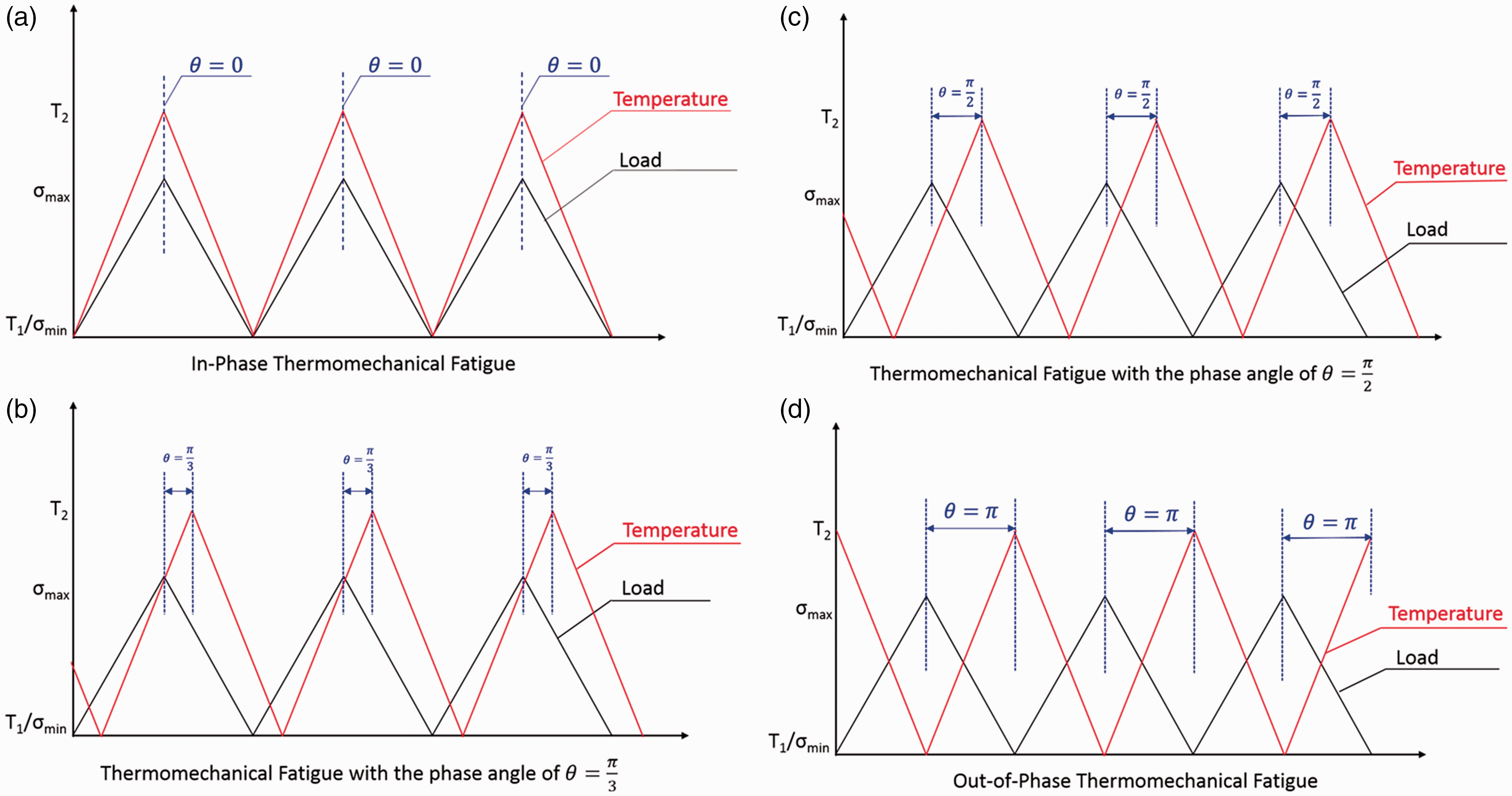
Under the thermomechanical fatigue loading, the tests involve cycling both temperature and load, and these cycles will have various phase differences, and will not be together at the same frequency. There are four different cases considered in the present analysis, as shown in Figure 1, including:
Case 1: the angle phase between the load and thermal cycle is θ = 0, i.e., the load and temperature are at the same frequency; Case 2: the angle phase between the load and thermal cycle is θ = π/3; Case 3: the angle phase between the load and thermal cycle is θ = π/2; Case 4: the angle phase between the load and thermal cycle is θ = π, i.e., the load peaks while the temperature is at a minimum value. The schematic of thermomechanical fatigue loading corresponding to different phase angles of (a) θ = 0; (b) θ = π/3; (c) θ = π/2; and (d) θ = π.
The testing temperature affects the mechanical behavior of CMCs, i.e., matrix microcracking, fiber/matrix interface debonding, and thermal residual stress. If the radial thermal expansion coefficient of the matrix is higher than the coefficient of the fibers, at a testing temperature T lower than the processing temperature T0, i.e., T < T0, the radial thermal residual stresses are compressive stresses. The fiber/matrix interface shear stress can be described using the following equation.

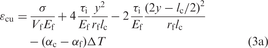
Upon unloading and reloading, the fiber/matrix interface debonding and sliding occur in the interface debonded region, as shown in Figure 2. When the fiber/matrix interface partially debonds, the unloading strain ɛcu and reloading strain ɛcr are determined using the following equation.
The schematic figure for fiber slipping relative to matrix upon (a) unloading; and (b) reloading.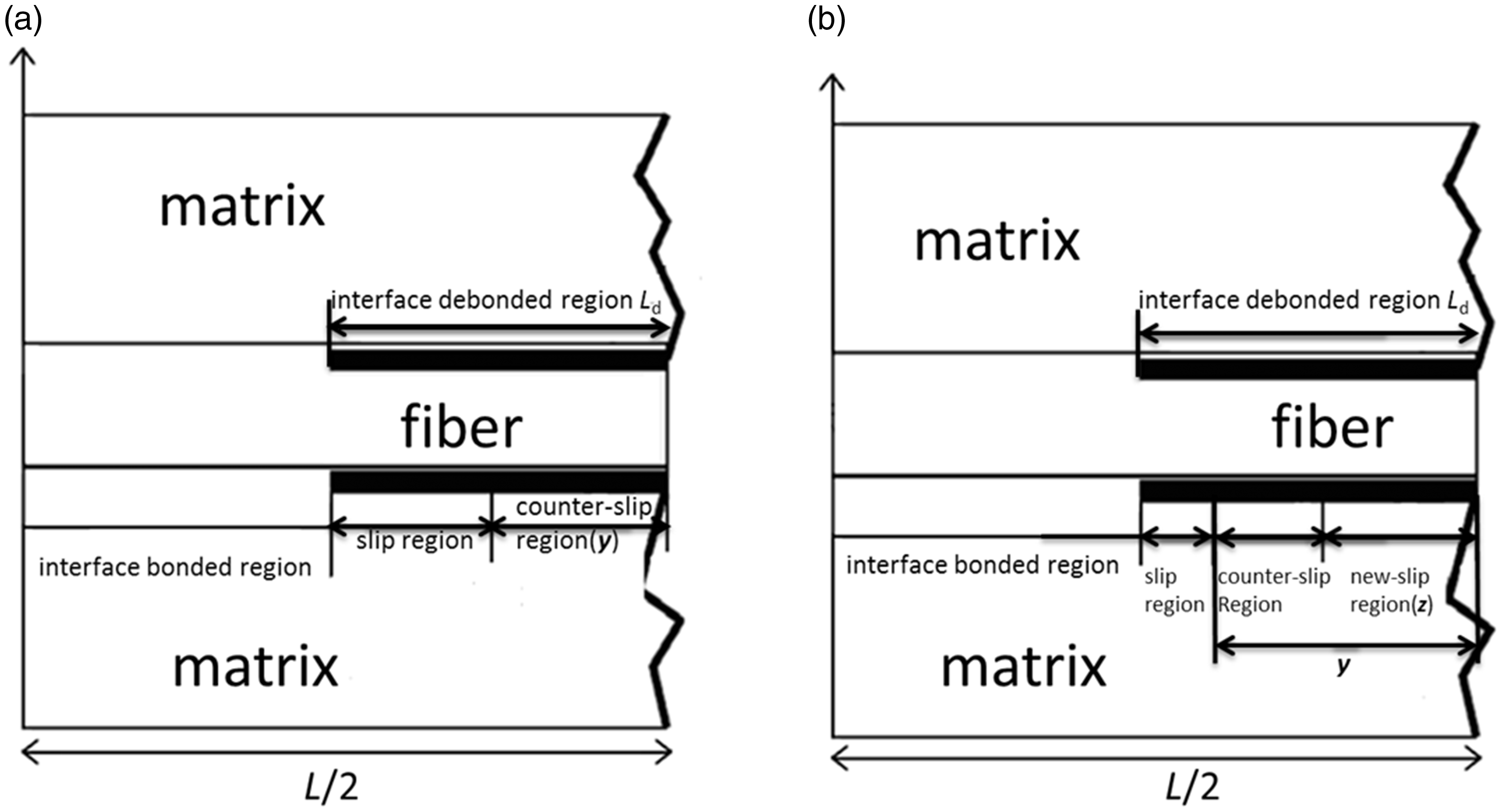
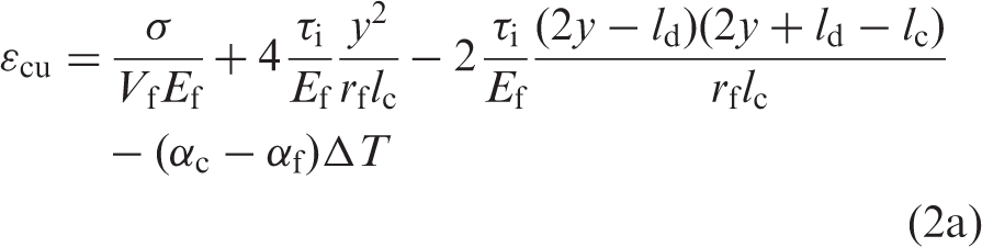
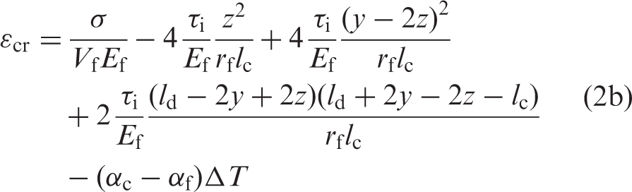
When the fiber/matrix interface completely debonds, the unloading strain ɛcu and reloading strain ɛcr are determined using the following equations.
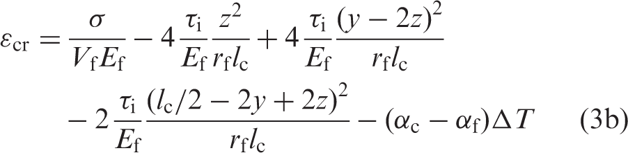
The fatigue hysteresis loops area is defined using the following equation.
Substituting the unloading and reloading strains in equations (2) and (3) into equation (4), the fatigue hysteresis loops can be obtained.
Discussion
The ceramic composite system of SiC/SiC is used for the case study and its material properties are given by: Vf = 35%, Ef = 230 GPa, Em = 300 GPa, rf = 7.5 µm, ζd = 0.1 J/m2, αrf = 2.9 × 10⁻⁶/K, αlf = 3.9 × 10⁻⁶/K, αrm = 4.6 × 10⁻⁶/K, αlm = 2 × 10⁻⁶/K, T0 = 1000 ℃, T1 = 100 ℃, and T2 = 1000 ℃. The comparisons of thermomechanical fatigue hysteresis loops under different phase angles have been investigated considering the effects of fiber volume fraction, fatigue peak stress, matrix crack spacing, fiber/matrix interface debonded energy, and fiber/matrix interface frictional coefficient.
Effect of fiber volume fraction
The fatigue hysteresis loops and fiber/matrix interface slip lengths of y/ld and z/ld under the thermomechanical fatigue loading of σmax = 240 MPa and phase angles of θ = 0, π/3, π/2, and π are shown in Figure 3, considering different fiber volume fraction of Vf = 30% and 40%.
(a) The fatigue hysteresis loops of different phase angles when Vf = 30%; (b) the fatigue hysteresis loops of different phase angles when Vf = 40%; (c) the fiber/matrix interface slip lengths versus applied stress with the phase angle of θ = 0 and Vf = 30, 40%; (d) the fiber/matrix interface slip lengths versus applied stress with the phase angle of θ = π/3 and Vf = 30, 40%; (e) the fiber/matrix interface slip lengths versus applied stress with the phase angle of θ = π/2 and Vf = 30, 40%; and (f) the fiber/matrix interface slip lengths versus applied stress with the phase angle of θ = π and Vf = 30, 40%.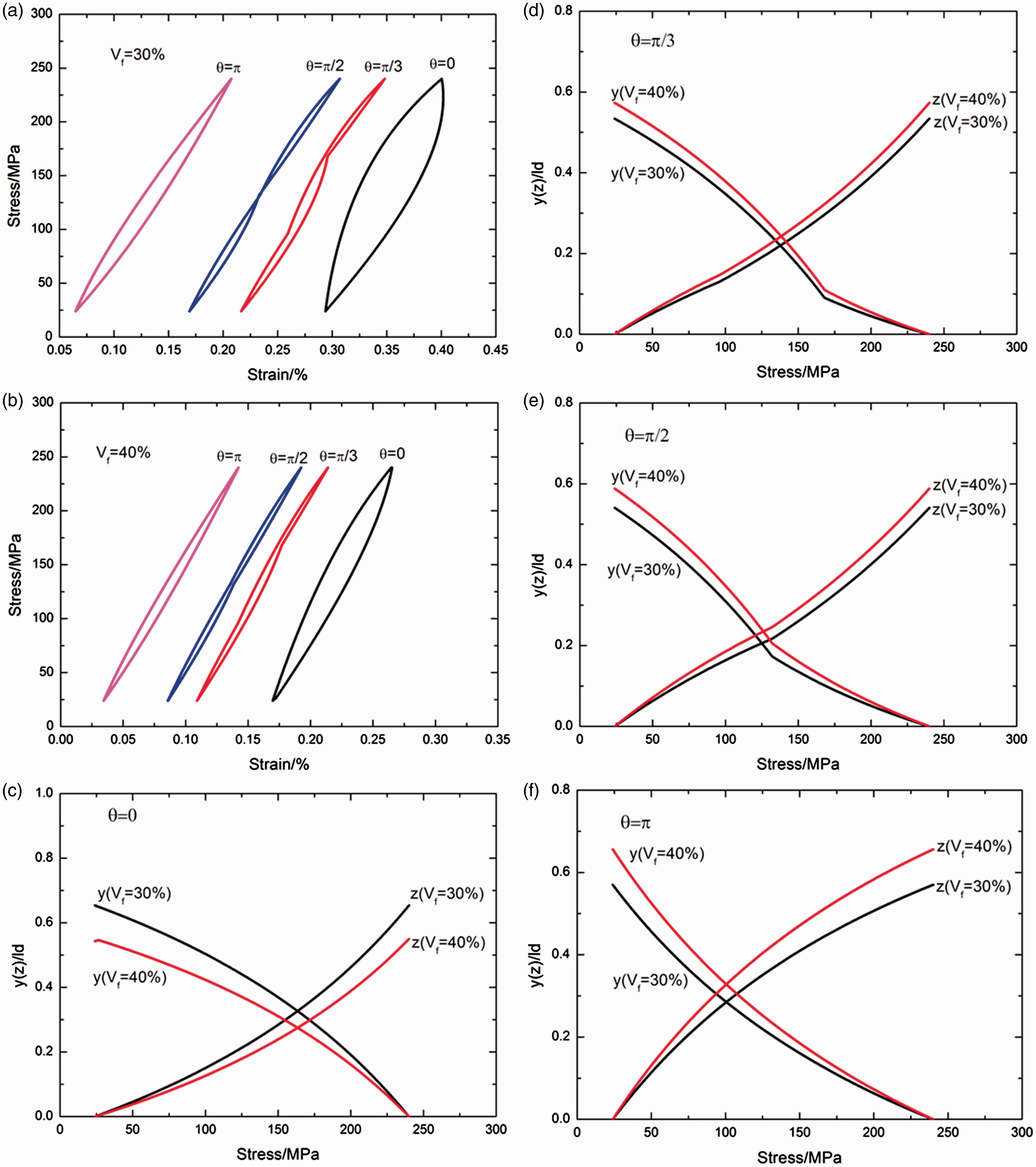
When the fiber volume fraction is Vf = 30%, the thermomechanical fatigue hysteresis loops corresponding to the phase angles of θ = 0, π/3, π/2, and π are shown in Figure 3(a), in which the shape, location, and area of fatigue hysteresis loops are affected by the phase angle. When the phase angle is θ = 0, the fatigue hysteresis loops correspond to the fiber/matrix interface completely debonding and the fiber partially sliding relative to the matrix in the fiber/matrix interface debonded region, as shown in Figure 3(a); and the unloading and reloading fiber/matrix interface slip lengths, i.e., y/ld and z/ld, increase nonlinearly, with decreasing or increasing applied stress, and approach to approximately 65% of entire fiber/matrix interface debonded length, i.e., y(σmin)/ld = z(σmax)/ld = 0.65, as shown in Figure 3(c). When the phase angle is θ = π/3, the fatigue hysteresis loops correspond to the fiber/matrix interface partially debonding and the fiber partially sliding relative to the matrix in the fiber/matrix interface debonded region, the fiber/matrix interface debonded length occupies 98% of matrix crack spacing, and the shape of fatigue hysteresis loops changes at the unloading stress of σtr_u = 168 MPa and the reloading stress of σtr_r = 96 MPa, as shown in Figure 3(a); and the unloading and reloading fiber/matrix interface slip lengths, i.e., y/ld and z/ld, increase nonlinearly with decreasing or increasing applied stress, and change at the unloading or reloading transition stress of σtr_u = 168 MPa and σtr_r = 96 MPa, and approach to approximately 53% of entire fiber/matrix interface debonded length, i.e., y(σmin)/ld = z(σmax)/ld = 0.53, as shown in Figure 3(d). When the phase angle is θ = π/2, the fatigue hysteresis loops correspond to the fiber/matrix interface partially debonding and the fiber partially sliding relative to the matrix in the fiber/matrix interface debonded region, the fiber/matrix interface debonded length occupies about 88.2% of matrix crack spacing, and the shape of fatigue hysteresis loops changes at the unloading and the reloading stress of σtr_u = σtr_r = 132 MPa, as shown in Figure 3(a); and the unloading and reloading fiber/matrix interface slip lengths, i.e., y/ld and z/ld, increase nonlinearly with decreasing or increasing applied stress, and change at the unloading or reloading transition stress of σtr_u = σtr_r = 132 MPa, and approach to approximately 54% of entire fiber/matrix interface debonded length, i.e., y(σmin)/ld = z(σmax)/ld = 0.54, as shown in Figure 3(e). When the phase angle is θ = π, the fatigue hysteresis loops correspond to the fiber/matrix interface partially debonding and the fiber partially sliding relative to the matrix in the interface debonded region, and the fiber/matrix interface debonded length occupies about 68% of matrix crack spacing, as shown in Figure 3(a); and the unloading and reloading fiber/matrix interface slip lengths, i.e., y/ld and z/ld, increase nonlinearly with decreasing or increasing applied stress, and approach to approximately 57% of entire fiber/matrix interface debonded length, i.e., y(σmin)/ld = z(σmax)/ld = 0.57, as shown in Figure 3(f).
When the fiber volume fraction is Vf = 40%, the thermomechanical fatigue hysteresis loops corresponding to the phase angles of θ = 0, π/3, π/2 and π are shown in Figure 3(b). When the phase angle is θ = 0, the fatigue hysteresis loops correspond to the fiber/matrix interface partially debonding and the fiber partially sliding relative to the matrix in the interface debonded region, and the interface debonded length occupies 76% of matrix crack spacing, as shown in Figure 3(b); and the unloading and reloading fiber/matrix interface slip lengths, i.e., y/ld and z/ld, increase nonlinearly with decreasing or increasing applied stress, and approach to approximately 54.3% and 54.9% of entire fiber/matrix interface debonded length, i.e., y(σmin)/ld = 0.543 and z(σmax)/ld = 0.549, as shown in Figure 3(c). When the phase angle is θ = π/3, the fatigue hysteresis loops correspond to the fiber/matrix interface partially debonding and the fiber partially sliding relative to the matrix in the fiber/matrix interface debonded region, the fiber/matrix interface debonded length occupies about 59.5% of matrix crack spacing, and the shape of fatigue hysteresis loops changes at σtr_u = 168 MPa and σtr_r = 96 MPa, as shown in Figure 3(b); and the unloading and reloading fiber/matrix interface slip lengths, i.e., y/ld and z/ld, increase nonlinearly with decreasing or increasing applied stress, and change at the transition stress of σtr_u = 168 MPa and σtr_r = 96 MPa, and approach to approximately 57.3% of entire fiber/matrix interface debonded length, i.e., y(σmin)/ld = z(σmax)/ld = 0.573, as shown in Figure 3(d). When the phase angle is θ = π/2, the fatigue hysteresis loops correspond to the fiber/matrix interface partially debonding and the fiber partially sliding relative to the matrix in the fiber/matrix interface debonded region, the fiber/matrix interface debonded length occupies about 53.6% of matrix crack spacing, and the shape of fatigue hysteresis loops changes at the transition stress of σtr_u = σtr_r = 132 MPa, as shown in Figure 3(b); and the unloading and reloading fiber/matrix interface slip lengths, i.e., y/ld and z/ld, increase nonlinearly with decreasing or increasing applied stress, and change at the transition stress of σtr_u = σtr_r = 132 MPa, and approach to approximately 58.8% of entire fiber/matrix interface debonded length, i.e., y(σmin)/ld = z(σmax)/ld = 0.588, as shown in Figure 3(e). When the phase angle is θ = π, the fatigue hysteresis loops correspond to the fiber/matrix interface partially debonding and the fiber partially sliding relative to the matrix in the fiber/matrix interface debonded region, and the interface debonded length occupies about 41.3% of matrix crack spacing, as shown in Figure 3(b); and the unloading and reloading fiber/matrix interface slip lengths, i.e., y/ld and z/ld, increase nonlinearly with the decreasing or increasing applied stress, and approach to approximately 65.6% of entire fiber/matrix interface debonded length, i.e., y(σmin)/ld = z(σmax)/ld = 0.656, as shown in Figure 3(f).
With the increasing fiber volume fraction, the fatigue hysteresis loops area decreases; the unloading strain at the valley stress decreases; the fiber/matrix interface slip lengths at the phase angle of θ = π/3, π/2, and π increase due to the fiber/matrix interface partially debonding, and decreases at the phase angle of θ = 0 due to the fiber/matrix interface completely debonding.
Effect of fatigue peak stress
The fatigue hysteresis loops under the thermomechanical fatigue loading of the phase angles of θ = 0, π/3, π/2, and π are shown in Figure 4, considering different fatigue peak stresses of σmax = 200 and 250 MPa, and the fiber volume fraction is Vf = 30%.
(a) The fatigue hysteresis loops of different phase angles when σmax = 200 MPa; and (b) the fatigue hysteresis loops of different phase angles when σmax = 250 MPa.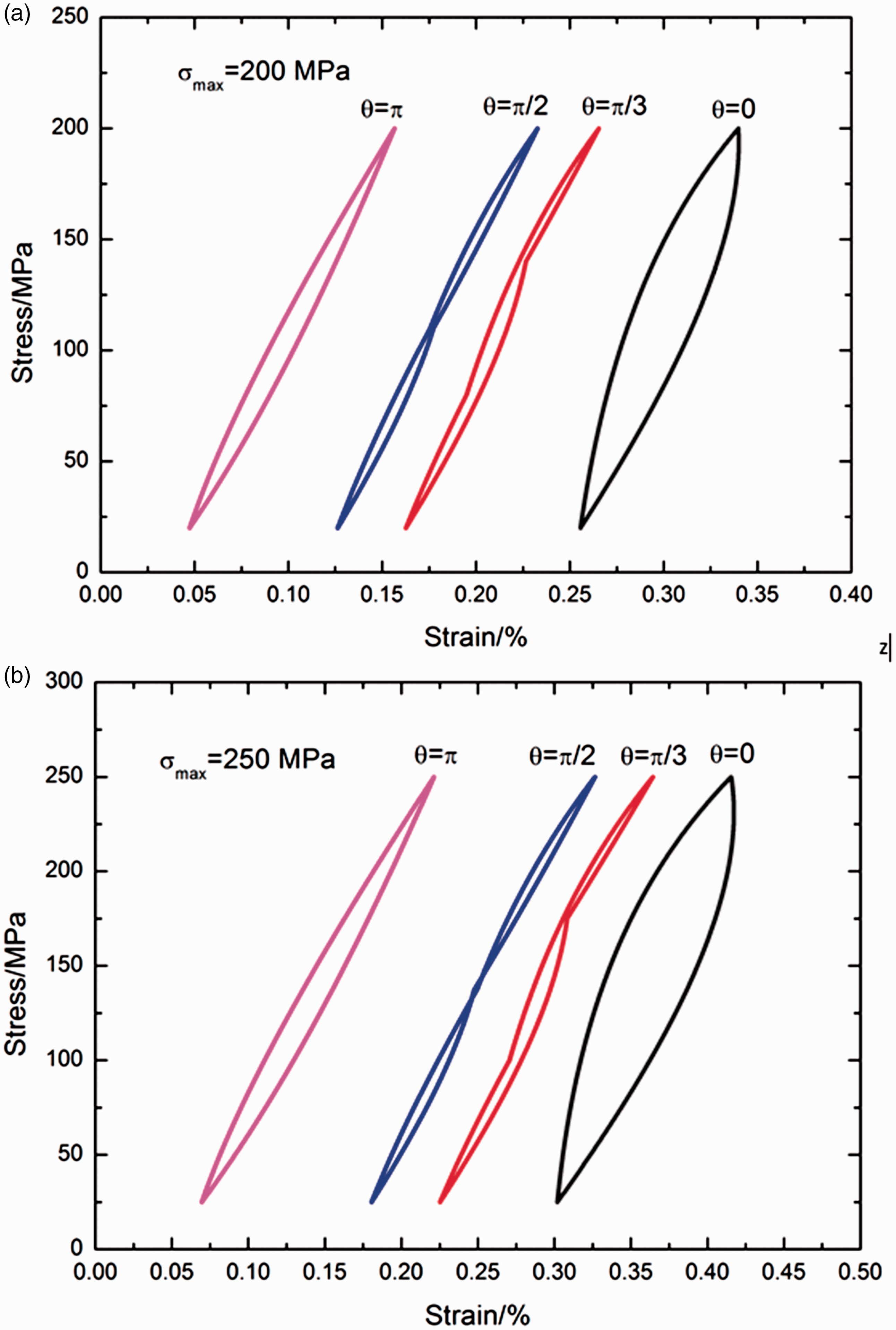
When the fatigue peak stress is σmax = 200 MPa, the thermomechanical fatigue hysteresis loops corresponding to the phase angles of θ = 0, π/3, π/2, and π are shown in Figure 4(a). When the phase angle is θ = 0, the fatigue hysteresis loops correspond to the fiber/matrix interface partially debonding and the fiber partially sliding relative to the matrix in the fiber/matrix interface debonded region, and the fiber/matrix interface debonded length occupies about 99% of matrix crack spacing; and the unloading fiber/matrix interface counter slip length and reloading fiber/matrix interface new slip length increases nonlinearly with decreasing or increasing applied stress, and approach to approximately 53.6% of entire fiber/matrix interface debonded length, i.e., y(σmin)/ld = z(σmax)/ld = 0.536. When the phase angle is θ = π/3, the fatigue hysteresis loops correspond to the fiber/matrix interface partially debonding and the fiber partially sliding relative to the matrix in the fiber/matrix interface debonded region, the fiber/matrix interface debonded length occupies about 78.2% of matrix crack spacing, and the shape of fatigue hysteresis loops changes at the transition stress of σtr_u = 140 MPa and σtr_r = 80 MPa; and the unloading and reloading fiber/matrix interface slip lengths, i.e., y/ld and z/ld, increase nonlinearly with decreasing or increasing applied stress, and change at the transition stress of σtr_u = 140 MPa and σtr_r = 80 MPa, and approach to approximately 55.2% of entire fiber/matrix interface debonded length, i.e., y(σmin)/ld = z(σmax)/ld = 0.552. When the phase angle is θ = π/2, the fatigue hysteresis loops correspond to the fiber/matrix interface partially debonding and the fiber partially sliding relative to the matrix in the fiber/matrix interface debonded region, the fiber/matrix interface debonded length occupies about 70.5% of matrix crack spacing, and the shape of fatigue hysteresis loops changes at the transition stress of σtr_u = σtr_r = 110 MPa; and the unloading and reloading fiber/matrix interface slip lengths, i.e., y/ld and z/ld, increase nonlinearly with decreasing or increasing applied stress, and change at the transition stress of σtr_u = σtr_r = 110 MPa, and approach to approximately 56.3% of entire fiber/matrix interface debonded length, i.e., y(σmin)/ld = z(σmax)/ld = 0.563. When the phase angle is θ = π, the fatigue hysteresis loops correspond to the fiber/matrix interface partially debonding and the fiber partially sliding relative to the matrix in the fiber/matrix interface debonded region, and the fiber/matrix interface debonded length occupies about 54.3% of matrix crack spacing; and the unloading and reloading fiber/matrix interface slip lengths, i.e., y/ld and z/ld, increase nonlinearly with decreasing or increasing applied stress, and approach to approximately 61% of entire fiber/matrix interface debonded length, i.e., y(σmin)/ld = z(σmax)/ld = 0.61.
When the fatigue peak stress is σmax = 250 MPa, the thermomechanical fatigue hysteresis loops corresponding to the phase angles of θ = 0, π/3, π/2, and π are shown in Figure 4(b). When the phase angle is θ = 0, the fatigue hysteresis loops correspond to the fiber/matrix interface completely debonding and the fiber partially sliding relative to the matrix in the fiber/matrix interface debonded region; and the unloading fiber/matrix interface counter slip length and reloading fiber/matrix interface new slip length increases nonlinearly with decreasing or increasing applied stress, and approach to approximately 68.3% of entire fiber/matrix interface debonded length, i.e., y(σmin)/ld = z(σmax)/ld = 0.683. When the phase angle is θ = π/3, the fatigue hysteresis loops correspond to the fiber/matrix interface completely debonding and the fiber partially sliding relative to the matrix in the fiber/matrix interface debonded region, and the shape of fatigue hysteresis loops changes at the transition stress of σtr_u = 140 MPa and σtr_r = 80 MPa; and the unloading and reloading fiber/matrix interface slip lengths, i.e., y/ld and z/ld, increase nonlinearly with decreasing or increasing applied stress, and change at the transition stress of σtr_u = 175 MPa and σtr_r = 100 MPa, and approach to approximately 54.4% of entire fiber/matrix interface debonded length, i.e., y(σmin)/ld = z(σmax)/ld = 0.544. When the phase angle is θ = π/2, the fatigue hysteresis loops correspond to the fiber/matrix interface partially debonding and the fiber partially sliding relative to the matrix in the fiber/matrix interface debonded region, the interface debonded length occupies about 92.6% of matrix crack spacing, and the shape of fatigue hysteresis loops changes at the transition stress of σtr_u = σtr_r = 137.5 MPa; and the unloading and reloading fiber/matrix interface slip lengths, i.e., y/ld and z/ld, increase nonlinearly with decreasing or increasing applied stress, and change at the transition stress of σtr_u = σtr_r = 137.5 MPa, and approach to approximately 53.6% of entire fiber/matrix interface debonded length, i.e., y(σmin)/ld = z(σmax)/ld = 0.536. When the phase angle is θ = π, the fatigue hysteresis loops correspond to the fiber/matrix interface partially debonding and the fiber partially sliding relative to the matrix in the fiber/matrix interface debonded region, and the fiber/matrix interface debonded length occupies about 71.4% of matrix crack spacing; and the unloading and reloading fiber/matrix interface slip lengths, i.e., y/ld and z/ld, increase nonlinearly with decreasing or increasing applied stress, and approach to approximately 56.2% of entire fiber/matrix interface debonded length, i.e., y(σmin)/ld = z(σmax)/ld = 0.562.
With the increasing fatigue peak stress, the fatigue hysteresis loops area increases; the unloading strain at the valley stress increases; the fiber/matrix interface slip lengths at the phase angle of θ = π/3, π/2, and π decrease, and increases at the phase angle of θ = 0.
Effect of matrix crack spacing
The fatigue hysteresis loops and fiber/matrix interface slip lengths of 2y/lc and 2z/lc under the thermomechanical fatigue loading of σmax = 240 MPa and the phase angles of θ = 0, π/3, π/2, and π are shown in Figure 5, considering different matrix crack spacing of lc = 200 and 300 µm, and the fiber volume fraction is Vf = 30%.
(a) The fatigue hysteresis loops of different phase angles when lc = 200 µm; (b) the fatigue hysteresis loops of different phase angles when lc = 300 µm; (c) the fiber/matrix interface slip lengths versus applied stress with the phase angle of θ = 0 and lc = 200 and 300 µm; (d) the fiber/matrix interface slip lengths versus applied stress with the phase angle of θ = π/3 and lc = 200 and 300 µm; (e) the fiber/matrix interface slip lengths versus applied stress with the phase angle of θ = π/2 and lc = 200 and 300 µm; and (f) the fiber/matrix interface slip lengths versus applied stress with the phase angle of θ = π and lc = 200 and 300 µm.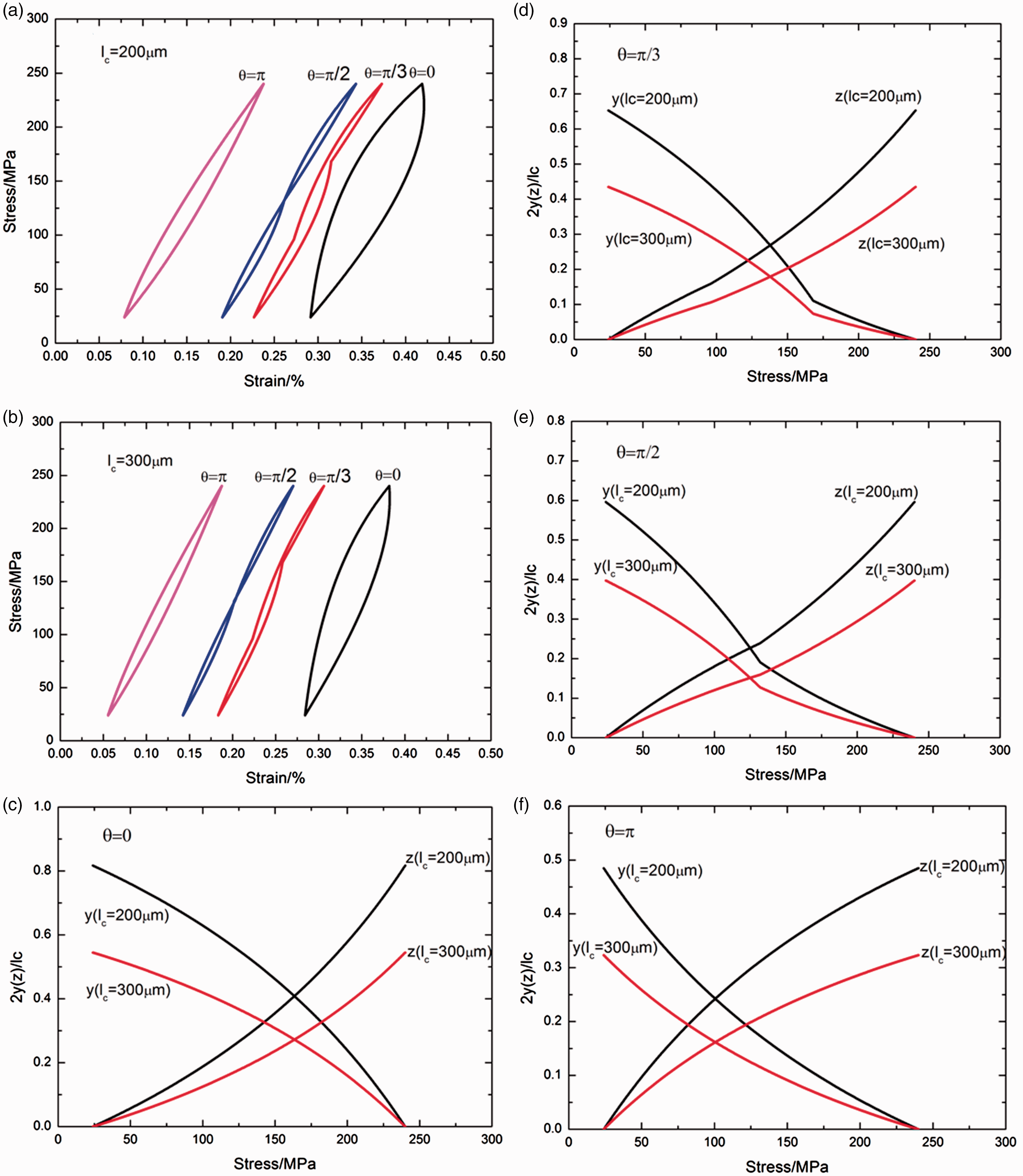
When the matrix crack spacing is lc = 200 µm, the thermomechanical fatigue hysteresis loops corresponding to the phase angles of θ = 0, π/3, π/2 and π are shown in Figure 5(a). When the phase angle is θ = 0, the fatigue hysteresis loops correspond to the fiber/matrix interface completely debonding and the fiber partially sliding relative to the matrix in the fiber/matrix interface debonded region, as shown in Figure 5(a); and the unloading fiber/matrix interface counter slip length and reloading fiber/matrix interface new slip length increases nonlinearly with decreasing or increasing applied stress, and approach to approximately 81.7% of entire matrix crack spacing, i.e., 2y(σmin)/lc = 2z(σmax)/lc = 0.817, as shown in Figure 5(c). When the phase angle is θ = π/3, the fatigue hysteresis loops correspond to the fiber/matrix interface completely debonding and the fiber partially sliding relative to the matrix in the fiber/matrix interface debonded region, and the shape of fatigue hysteresis loops changes at the transition stress of σtr_u = 168 MPa and σtr_r = 96 MPa, as shown in Figure 5(a); and the unloading and reloading fiber/matrix interface slip lengths, i.e., 2y/lc and 2z/lc, increase nonlinearly with the decreasing or increasing applied stress, and change at the transition stress of σtr_u = 168 MPa and σtr_r = 96 MPa, and approach to approximately 65.2% of entire matrix crack spacing, i.e., 2y(σmin)/lc = 2z(σmax)/lc = 0.652, as shown in Figure 5(d). When the phase angle is θ = π/2, the fatigue hysteresis loops correspond to the fiber/matrix interface completely debonding and the fiber partially sliding relative to the matrix in the fiber/matrix interface debonded region, and the shape of fatigue hysteresis loops changes at the transition stress of σtr_u = σtr_r = 132 MPa, as shown in Figure 5(a); and the unloading and reloading fiber/matrix interface slip lengths, i.e., 2y/lc and 2z/lc, increase nonlinearly with decreasing or increasing applied stress, and change at the transition stress of σtr_u = σtr_r = 132 MPa, and approach to approximately 59.5% of entire fiber/matrix interface debonded length, i.e., 2y(σmin)/lc = 2z(σmax)/lc = 0.595, as shown in Figure 5(e). When the phase angle is θ = π, the fatigue hysteresis loops correspond to the fiber/matrix interface partially debonding and the fiber partially sliding relative to the matrix in the fiber/matrix interface debonded region, and the fiber/matrix interface debonded length occupies about 85% of matrix crack spacing, as shown in Figure 5(a); and the unloading and reloading fiber/matrix interface slip lengths, i.e., 2y/lc and 2z/lc, increase nonlinearly with decreasing or increasing applied stress, and approach to approximately 48.4% of entire matrix crack spacing, i.e., 2y(σmin)/lc = 2z(σmax)/lc = 0.484, as shown in Figure 5(f).
When the matrix crack spacing is lc = 300 µm, the thermomechanical fatigue hysteresis loops corresponding to the phase angles of θ = 0, π/3, π/2 and π are shown in Figure 5(b). When the phase angle is θ = 0, the fatigue hysteresis loops correspond to the fiber/matrix interface completely debonding and the fiber partially sliding relative to the matrix in the fiber/matrix interface debonded region, as shown in Figure 5(b); and the unloading fiber/matrix interface counter slip length and reloading fiber/matrix interface new slip length increases nonlinearly with decreasing or increasing applied stress, and approach to approximately 54.4% of entire matrix crack spacing, i.e., 2y(σmin)/lc = 2z(σmax)/lc = 0.544, as shown in Figure 5(c). When the phase angle is θ = π/3, the fatigue hysteresis loops correspond to the fiber/matrix interface partially debonding and the fiber partially sliding relative to the matrix in the fiber/matrix interface debonded region, the interface debonded length occupies about 81.5% of matrix crack spacing, and the shape of fatigue hysteresis loops changes at the transition stress of σtr_u = 168 MPa and σtr_r = 96 MPa, as shown in Figure 5(a); and the unloading and reloading fiber/matrix interface slip lengths, i.e., 2y/lc and 2z/lc, increase nonlinearly with decreasing or increasing applied stress, and change at the transition stress of σtr_u = 168 MPa and σtr_r = 96 MPa, and approach to approximately 43.5% of entire of matrix crack spacing, i.e., 2y(σmin)/lc = 2z(σmax)/lc = 0.435, as shown in Figure 5(d). When the phase angle is θ = π/2, the fatigue hysteresis loops correspond to the fiber/matrix interface partially debonding and the fiber partially sliding relative to the matrix in the fiber/matrix interface debonded region, the fiber/matrix interface debonded length occupies about 73.4% of matrix crack spacing, and the shape of fatigue hysteresis loops changes at the transition stress of σtr_u = σtr_r = 132 MPa, as shown in Figure 5(a); and the unloading and reloading fiber/matrix interface slip lengths, i.e., 2y/lc and 2z/lc, increase nonlinearly with decreasing or increasing applied stress, and change at the transition stress of σtr_u = σtr_r = 132 MPa, and approach to approximately 39.7% of entire matrix crack spacing, i.e., 2y(σmin)/lc = 2z(σmax)/lc = 0.397, as shown in Figure 5(e). When the phase angle is θ = π, the fatigue hysteresis loops correspond to the fiber/matrix interface partially debonding and the fiber partially sliding relative to the matrix in the fiber/matrix interface debonded region, and the fiber/matrix interface debonded length occupies about 56.6% of matrix crack spacing, as shown in Figure 5(a); and the unloading and reloading fiber/matrix interface slip lengths, i.e., 2y/lc and 2z/lc, increase nonlinearly with the decreasing or increasing applied stress, and approach to approximately 32.3% of entire matrix crack spacing, i.e., 2y(σmin)/lc = 2z(σmax)/lc = 0.323, as shown in Figure 5(f).
With the increasing matrix crack spacing, the fatigue hysteresis loops area decreases; the unloading strain at the valley stress decreases; the fiber/matrix interface slip lengths at the phase angle of θ = 0, π/3, π/2, and π decrease.
Effect of interface frictional coefficient
The fatigue hysteresis loops under the thermomechanical fatigue loading of σmax = 240 MPa and the phase angles of θ = 0, π/3, π/2, and π are shown in Figure 6, considering different fiber/matrix interface frictional coefficient of μ = 0.03 and 0.05, and the fiber volume fraction of 30%.
(a) The fatigue hysteresis loops of different phase angles when μ = 0.03; and (b) the fatigue hysteresis loops of different phase angles when μ = 0.05.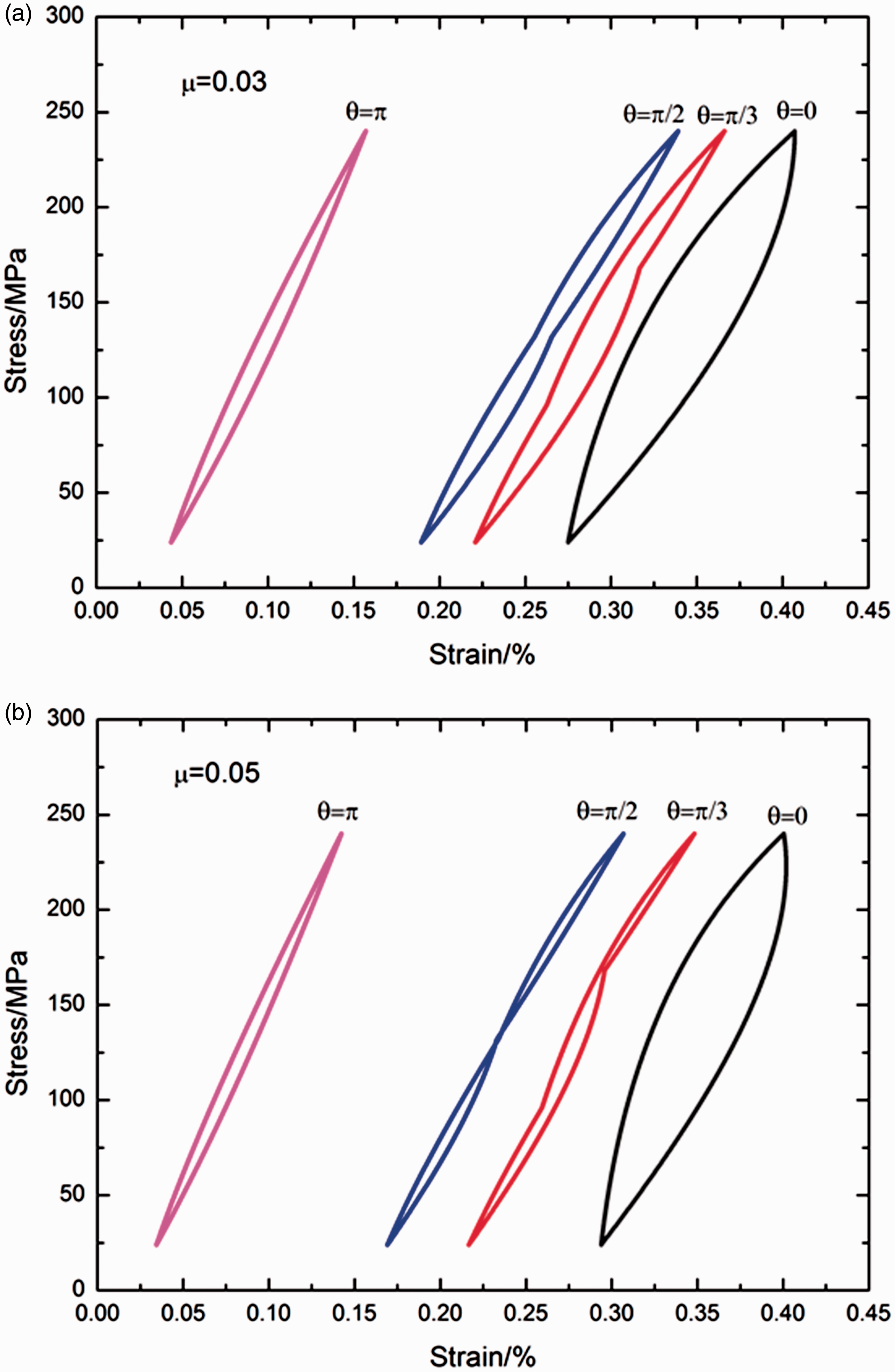
When the fiber/matrix interface frictional coefficient is μ = 0.03, the thermomechanical fatigue hysteresis loops corresponding to the phase angles of θ = 0, π/3, π/2 and π are shown in Figure 6(a). When the phase angle is θ = 0, the fatigue hysteresis loops correspond to the fiber/matrix interface completely debonding and the fiber partially sliding relative to the matrix in the fiber/matrix interface debonded region; and the unloading fiber/matrix interface counter slip length and reloading fiber/matrix interface new slip length increases nonlinearly with decreasing or increasing applied stress, and approach to approximately 71% of the fiber/matrix interface debonded length, i.e., y(σmin)/ld = z(σmax)/ld = 0.71. When the phase angle is θ = π/3, the fatigue hysteresis loops correspond to the fiber/matrix interface completely debonding and the fiber partially sliding relative to the matrix in the fiber/matrix interface debonded region, and the shape of fatigue hysteresis loops changes at the transition stress of σtr_u = 168 MPa and σtr_r = 96 MPa; and the unloading and reloading fiber/matrix interface slip lengths, i.e., y/ld and z/ld, increase nonlinearly with decreasing or increasing applied stress, and change at the transition stress of σtr_u = 168 MPa and σtr_r = 96 MPa, and approach to approximately 61.1% of the fiber/matrix interface debonded length, i.e., y(σmin)/ld = z(σmax)/ld = 0.611. When the phase angle is θ = π/2, the fatigue hysteresis loops correspond to the fiber/matrix interface completely debonding and the fiber partially sliding relative to the matrix in the fiber/matrix interface debonded region, and the shape of fatigue hysteresis loops changes at the transition stress of σtr_u = σtr_r = 132 MPa; and the unloading and reloading fiber/matrix interface slip lengths, i.e., y/ld and z/ld, increase nonlinearly with decreasing or increasing applied stress, and change at the transition stress of σtr_u = σtr_r = 132 MPa, and approach to approximately 57.3% of the fiber/matrix interface debonded length, i.e., y(σmin)/ld = z(σmax)/ld = 0.573. When the phase angle is θ = π, the fatigue hysteresis loops correspond to the fiber/matrix interface partially debonding and the fiber partially sliding relative to the matrix in the fiber/matrix interface debonded region, and the fiber/matrix interface debonded length occupies about 53.3% of matrix crack spacing; and the unloading and reloading fiber/matrix interface slip lengths, i.e., y/ld and z/ld, increase nonlinearly with decreasing or increasing applied stress, and approach to approximately 63% of the fiber/matrix interface debonded length, i.e., y(σmin)/ld = z(σmax)/ld = 0.63.
When the fiber/matrix interface coefficient is μ = 0.05, the thermomechanical fatigue hysteresis loops corresponding to the phase angles of θ = 0, π/3, π/2, and π are shown in Figure 6(b). When the phase angle is θ = 0, the fatigue hysteresis loops correspond to the fiber/matrix interface completely debonding and the fiber partially sliding relative to the matrix in the fiber/matrix interface debonded region; and the unloading fiber/matrix interface counter slip length and reloading fiber/matrix interface new slip length increases nonlinearly with decreasing or increasing applied stress, and approach to approximately 65.3% of entire interface debonded length, i.e., y(σmin)/ld = z(σmax)/ld = 0.653. When the phase angle is θ = π/3, the fatigue hysteresis loops correspond to the fiber/matrix interface partially debonding and the fiber partially sliding relative to the matrix in the fiber/matrix interface debonded region, the fiber/matrix interface debonded length occupies about 97.8% of matrix crack spacing, and the shape of fatigue hysteresis loops changes at the transition stress of σtr_u = 168 MPa and σtr_r = 96 MPa; and the unloading and reloading fiber/matrix interface slip lengths, i.e., y/ld and z/ld, increase nonlinearly with decreasing or increasing applied stress, and change at the transition stress of σtr_u = 168 MPa and σtr_r = 96 MPa, and approach to approximately 53.4% of entire interface debonded length, i.e., y(σmin)/ld = z(σmax)/ld = 0.534. When the phase angle is θ = π/2, the fatigue hysteresis loops correspond to the fiber/matrix interface partially debonding and the fiber partially sliding relative to the matrix in the fiber/matrix interface debonded region, the fiber/matrix interface debonded length occupies about 88.2% of matrix crack spacing, and the shape of fatigue hysteresis loops changes at the transition stress of σtr_u = σtr_r = 132 MPa; and the unloading and reloading fiber/matrix interface slip lengths, i.e., y/ld and z/ld, increase nonlinearly with decreasing or increasing applied stress, and change at the transition stress of σtr_u = σtr_r = 132 MPa, and approach to approximately 54% of entire interface debonded length, i.e., y(σmin)/ld = z(σmax)/ld = 0.54. When the phase angle is θ = π, the fatigue hysteresis loops correspond to the fiber/matrix interface partially debonding and the fiber partially sliding relative to the matrix in the fiber/matrix interface debonded region, and the interface debonded length occupies about 41.3% of matrix crack spacing; and the unloading and reloading fiber/matrix interface slip lengths, i.e., y/ld and z/ld, increase nonlinearly with decreasing or increasing applied stress, and approach to approximately 65.6% of entire fiber/matrix interface debonded length, i.e., y(σmin)/ld = z(σmax)/ld = 0.656.
With the increasing fiber/matrix interface frictional coefficient, the fatigue hysteresis loops area decreases; the unloading strain at the valley stress decreases at the phase angles of θ = π/3, π/2, and π, and increases at the phase angle of θ = 0; the fiber/matrix interface slip lengths at the phase angles of θ = 0, π/3, and π/2 decrease, and increases at the phase angle of θ = π.
Effect of interface debonded energy
The fatigue hysteresis loops and fiber/matrix interface slip lengths of y/ld and z/ld under the thermomechanical fatigue loading of σmax = 240 MPa and the phase angles of θ = 0, π/3, π/2, and π are shown in Figure 7, considering different interface debonded energy of ζd = 0.1 and 0.5 J/m2, and the fiber volume fraction is Vf = 30%.
(a) The fatigue hysteresis loops of different phase angles when ζd = 0.1 J/m2; and (b) the fatigue hysteresis loops of different phase angles when ζd = 0.5 J/m2; (c) the interface slip lengths versus applied stress with the phase angle of θ = 0 and ζd = 0.1 and 0.5 J/m2; (d) the interface slip lengths versus applied stress with the phase angle of θ = π/3 and ζd = 0.1 and 0.5 J/m2; (e) the interface slip lengths versus applied stress with the phase angle of θ = π/2 and ζd = 0.1 and 0.5 J/m2; and (f) the interface slip lengths versus applied stress with the phase angle of θ = π and ζd = 0.1 and 0.5 J/m2.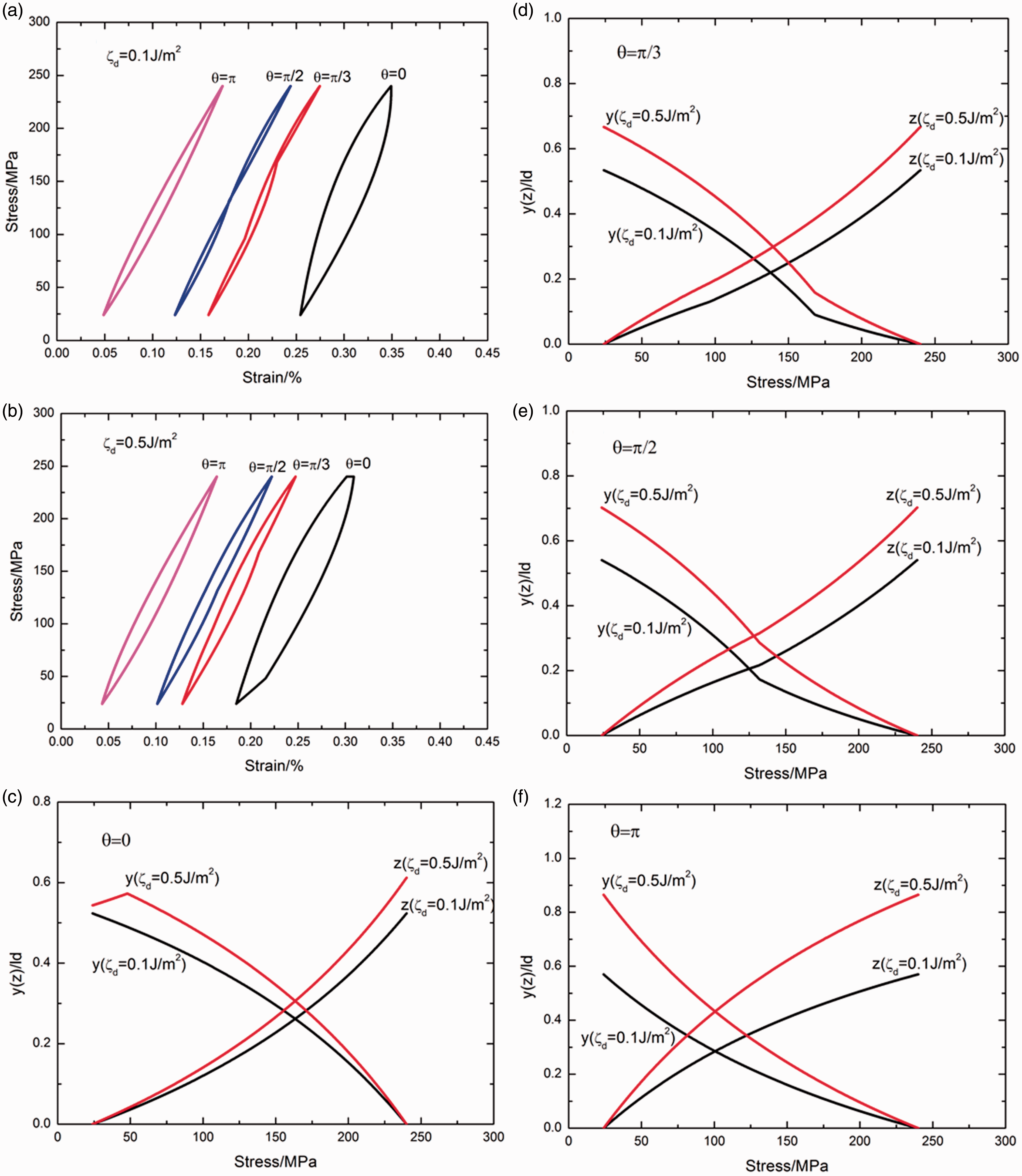
When the interface debonded energy is ζd = 0.1 J/m2, the thermomechanical fatigue hysteresis loops corresponding to the phase angles of θ = 0, π/3, π/2, and π are shown in Figure 7(a). When the phase angle is θ = 0, the fatigue hysteresis loops correspond to the fiber/matrix interface partially debonding and the fiber partially sliding relative to the matrix in the fiber/matrix interface debonded region, and the fiber/matrix interface debonded length occupies about 89% of matrix crack spacing, as shown in Figure 7(a); and the unloading fiber/matrix interface counter slip length and reloading fiber/matrix interface new slip length increases nonlinearly with decreasing or increasing applied stress, and approach to approximately 52.3% of the fiber/matrix interface debonded length, i.e., y(σmin)/ld = z(σmax)/ld = 0.523, as shown in Figure 7(c). When the phase angle is θ = π/3, the fatigue hysteresis loops correspond to the fiber/matrix interface partially debonding and the fiber partially sliding relative to the matrix in the fiber/matrix interface debonded region, the fiber/matrix interface debonded length occupies about 69.8% of matrix crack spacing, and the shape of fatigue hysteresis loops changes at the transition stress of σtr_u = 168 MPa and σtr_r = 96 MPa, as shown in Figure 7(a); and the unloading and reloading fiber/matrix interface slip lengths, i.e., y/ld and z/ld, increase nonlinearly with decreasing or increasing applied stress, and change at the transition stress of σtr_u = 168 MPa and σtr_r = 96 MPa, and approach to approximately 53.4% of the fiber/matrix interface debonded length, i.e., y(σmin)/ld = z(σmax)/ld = 0.534, as shown in Figure 7(d). When the phase angle is θ = π/2, the fatigue hysteresis loops correspond to the fiber/matrix interface partially debonding and the fiber partially sliding relative to the matrix in the fiber/matrix interface debonded region, the fiber/matrix interface debonded length occupies about 62.9% of matrix crack spacing, and the shape of fatigue hysteresis loops changes at the transition stress of σtr_u =σtr_r = 132 MPa, as shown in Figure 7(a); and the unloading and reloading fiber/matrix interface slip lengths, i.e., y/ld and z/ld, increase nonlinearly with decreasing or increasing applied stress, and change at the transition stress of σtr_u = σtr_r = 132 MPa, and approach to approximately 54% of the fiber/matrix interface debonded length, i.e., y(σmin)/ld = z(σmax)/ld = 0.54, as shown in Figure 7(e). When the phase angle is θ = π, the fatigue hysteresis loops correspond to the fiber/matrix interface partially debonding and the fiber partially sliding relative to the matrix in the fiber/matrix interface debonded region, and the interface debonded length occupies about 48.5% of matrix crack spacing, as shown in Figure 7(a); and the unloading and reloading fiber/matrix interface slip lengths, i.e., y/ld and z/ld, increase nonlinearly with decreasing or increasing applied stress, and approach to approximately 57% of the fiber/matrix interface debonded length, i.e., y(σmin)/ld = z(σmax)/ld = 0.57, as shown in Figure 7(f).
When the interface debonded energy is ζd = 0.5 J/m2, the thermomechanical fatigue hysteresis loops corresponding to the phase angles of θ = 0, π/3, π/2 and π are shown in Figure 7(b). When the phase angle is θ = 0, the fatigue hysteresis loops correspond to the fiber/matrix interface partially debonding and the fiber partially sliding relative to the matrix in the fiber/matrix interface debonded region, and the fiber/matrix interface debonded length occupies about 68.7% of matrix crack spacing, as shown in Figure 7(b); and the unloading fiber/matrix interface counter slip length and reloading fiber/matrix interface new slip length increases nonlinearly with decreasing or increasing applied stress, and approach to approximately 54.3% and 61.2% of the entire interface debonded length, i.e., y(σmin)/ld = 0.543 and z(σmax)/ld = 0.612, as shown in Figure 7(c). When the phase angle is θ = π/3, the fatigue hysteresis loops correspond to the fiber/matrix interface partially debonding and the fiber partially sliding relative to the matrix in the fiber/matrix interface debonded region, the fiber/matrix interface debonded length occupies about 53.7% of matrix crack spacing, and the shape of fatigue hysteresis loops changes at the transition stress of σtr_u = 168 MPa and σtr_r = 96 MPa, as shown in Figure 7(b); and the unloading and reloading fiber/matrix interface slip lengths, i.e., y/ld and z/ld, increase nonlinearly with decreasing or increasing applied stress, and change at the transition stress of σtr_u = 168 MPa and σtr_r = 96 MPa, and approach to approximately 66.7% of the entire fiber/matrix interface debonded length, i.e., y(σmin)/ld = z(σmax)/ld = 0.667, as shown in Figure 7(d). When the phase angle is θ = π/2, the fatigue hysteresis loops correspond to the fiber/matrix interface partially debonding and the fiber partially sliding relative to the matrix in the fiber/matrix interface debonded region, the fiber/matrix interface debonded length occupies about 48.5% of matrix crack spacing, and the shape of fatigue hysteresis loops changes at the transition stress of σtr_u = σtr_r = 132 MPa, as shown in Figure 7(b); and the unloading and reloading fiber/matrix interface slip lengths, i.e., y/ld and z/ld, increase nonlinearly with decreasing or increasing applied stress, and change at the transition stress of σtr_u = σtr_r = 132 MPa, and approach to approximately 70.2% of the entire fiber/matrix interface debonded length, i.e., y(σmin)/ld = z(σmax)/ld = 0.702, as shown in Figure 7(e). When the phase angle is θ = π, the fatigue hysteresis loops correspond to the fiber/matrix interface partially debonding and the fiber partially sliding relative to the matrix in the interface debonded region, and the interface debonded length occupies about 37.3% of matrix crack spacing, as shown in Figure 7(b); and the unloading and reloading interface slip lengths, i.e., y/ld and z/ld, increase nonlinearly with decreasing or increasing applied stress, and approach to approximately 86.5% of entire interface debonded length, i.e., y(σmin)/ld = z(σmax)/ld = 0.865, as shown in Figure 7(f).
With the increasing interface debonded energy, the fatigue hysteresis loops area increases; the unloading strain at the valley stress decreases; the fiber/matrix interface slip lengths at the phase angles of θ = 0, π/3, π/2, and π increase.
Experimental comparisons
Allen and Mall 9 investigated the thermomechanical and isothermal fatigue behavior of cross-ply SiC/MAS composite at the temperature range of 566 ℃ and 1093 ℃, with the stress ratio of 0.1. The material properties are given by: Vf = 40%, Ef = 200 GPa, Em = 138 GPa, rf = 7.5 µm, ζd = 0.1 J/m2, αf = 4 × 10⁻⁶/℃, αm = 2.4 × 10⁻⁶/℃, T0 = 1200 ℃.
In-phase thermomechanical fatigue loading
The experimental fatigue hysteresis loops under σmax = 120 MPa at the temperature range of 566 ℃ and 1093 ℃ with in-phase cyclic loading corresponding to the cycle number of N = 1 and 100 are illustrated in Figures 8 and 9.
(a) The experimental and theoretical fatigue hysteresis loops; and (b) the interface slip lengths versus applied stress curves of cross-ply SiC/MAS composite under in-phase thermomechanical fatigue loading with σmax = 120 MPa, the temperature range from T1 = 566℃ to T2 = 1093℃ at the N = 1. (a) The experimental and theoretical fatigue hysteresis loops; and (b) the interface slip lengths versus applied stress curves of cross-ply SiC/MAS composite under in-phase thermomechanical fatigue loading with σmax = 120 MPa, the temperature range from T1 = 566℃ to T2 = 1093℃ at the N = 100.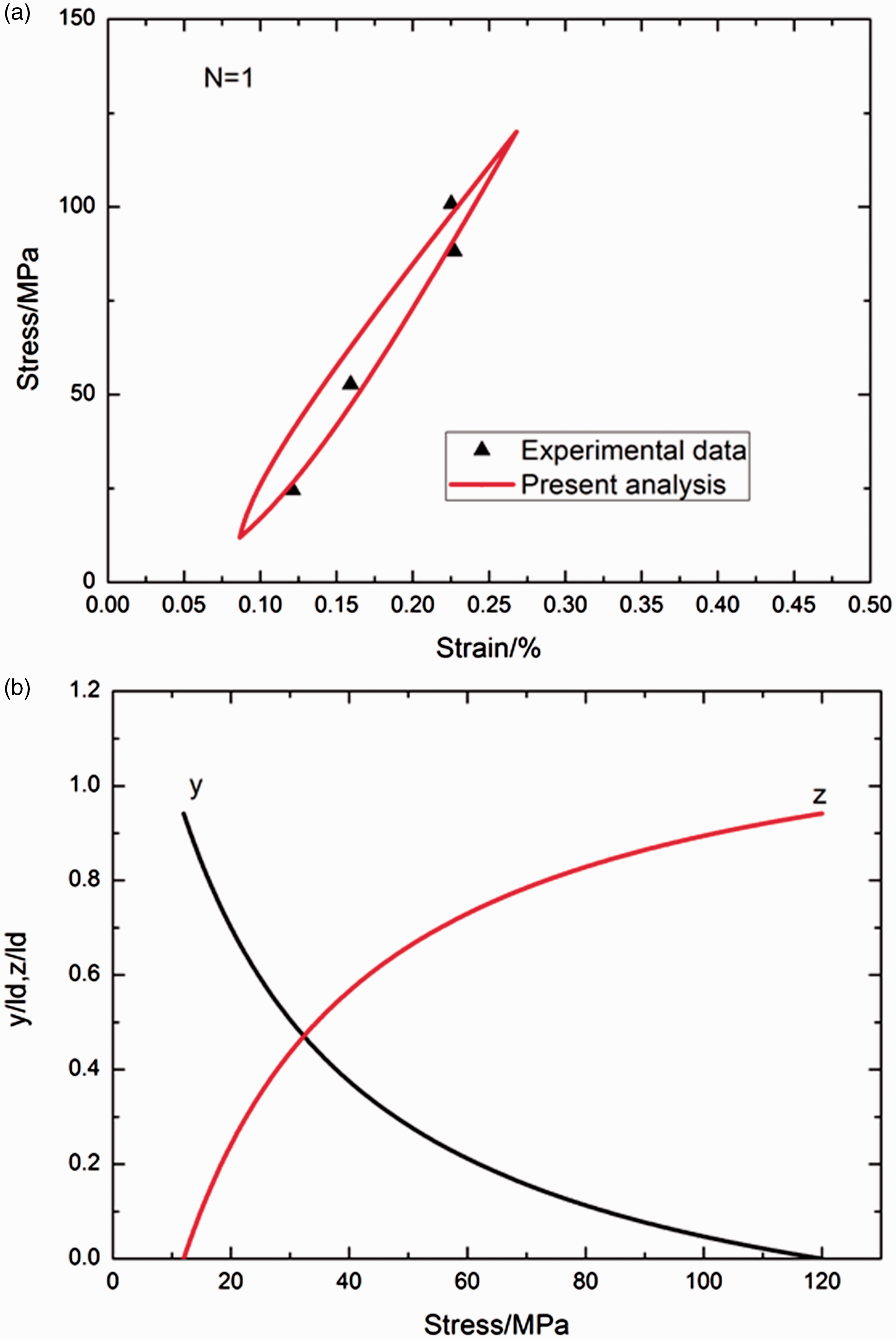
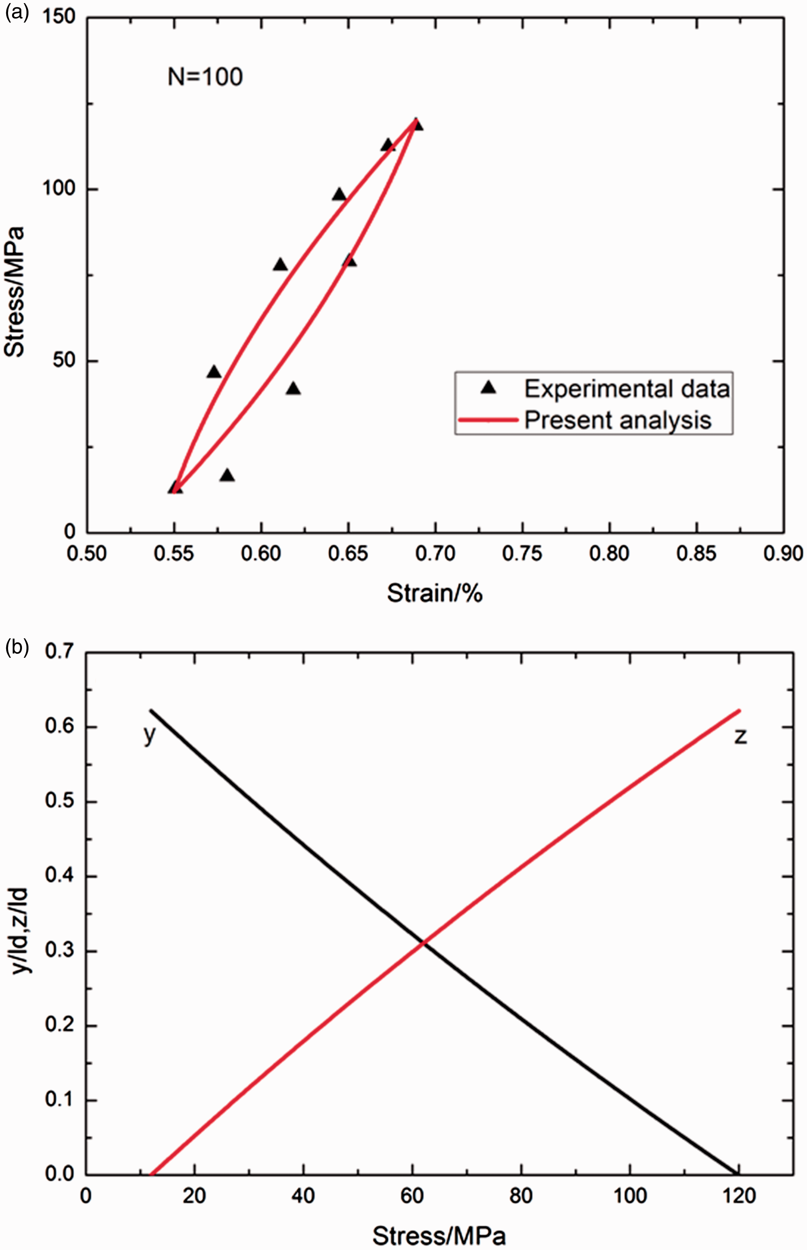
The fatigue hysteresis loops at the cyclic number of N = 1 and 100 correspond to the interface partially debonding and the fiber partially sliding relative to the matrix in the interface debonded region; and the interface counter-slip length upon unloading to the valley stress of σmin = 12 MPa, and the interface new slip length upon reloading to the peak stress of σmax = 120 MPa, both decrease with the increasing of cycle number, i.e., y(σmin)/ld = z(σmax)/ld = 0.941 when N = 1, y(σmin)/ld = z(σmax)/ld = 0.621 when N = 100, as shown in Figures 8 and 9.
Out-of-phase thermomechanical fatigue loading
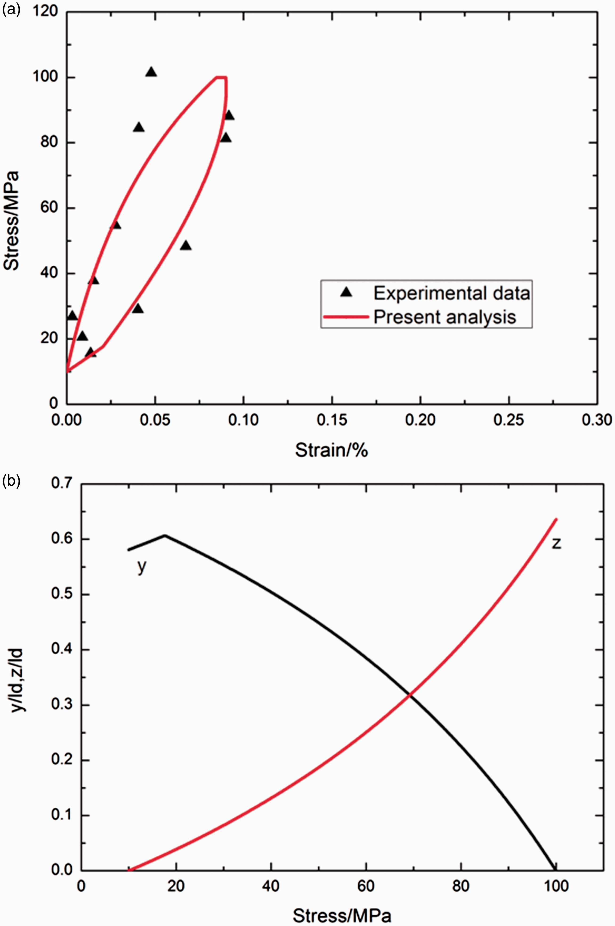
.The experimental and predicted fatigue hysteresis loops and interface slip lengths of cross-ply SiC/MAS composite under σmax = 75 and 100 MPa at the temperature range of 566 ℃ and 1093 ℃ with out-of-phase cyclic loading are illustrated in Figures 10 and 11.
(a) The experimental and theoretical fatigue hysteresis loops; and (b) the interface slip lengths versus applied stress curves of cross-ply SiC/MAS composite under out-of-phase thermomechanical fatigue loading with σmax = 75 MPa, the temperature range from T1 = 566℃ to T2 = 1093℃. (a) The experimental and theoretical fatigue hysteresis loops; and (b) the interface slip lengths versus applied stress curves of cross-ply SiC/MAS composite under out-of-phase thermomechanical fatigue loading with σmax = 100 MPa, the temperature range from T1 = 566℃ to T2 = 1093℃.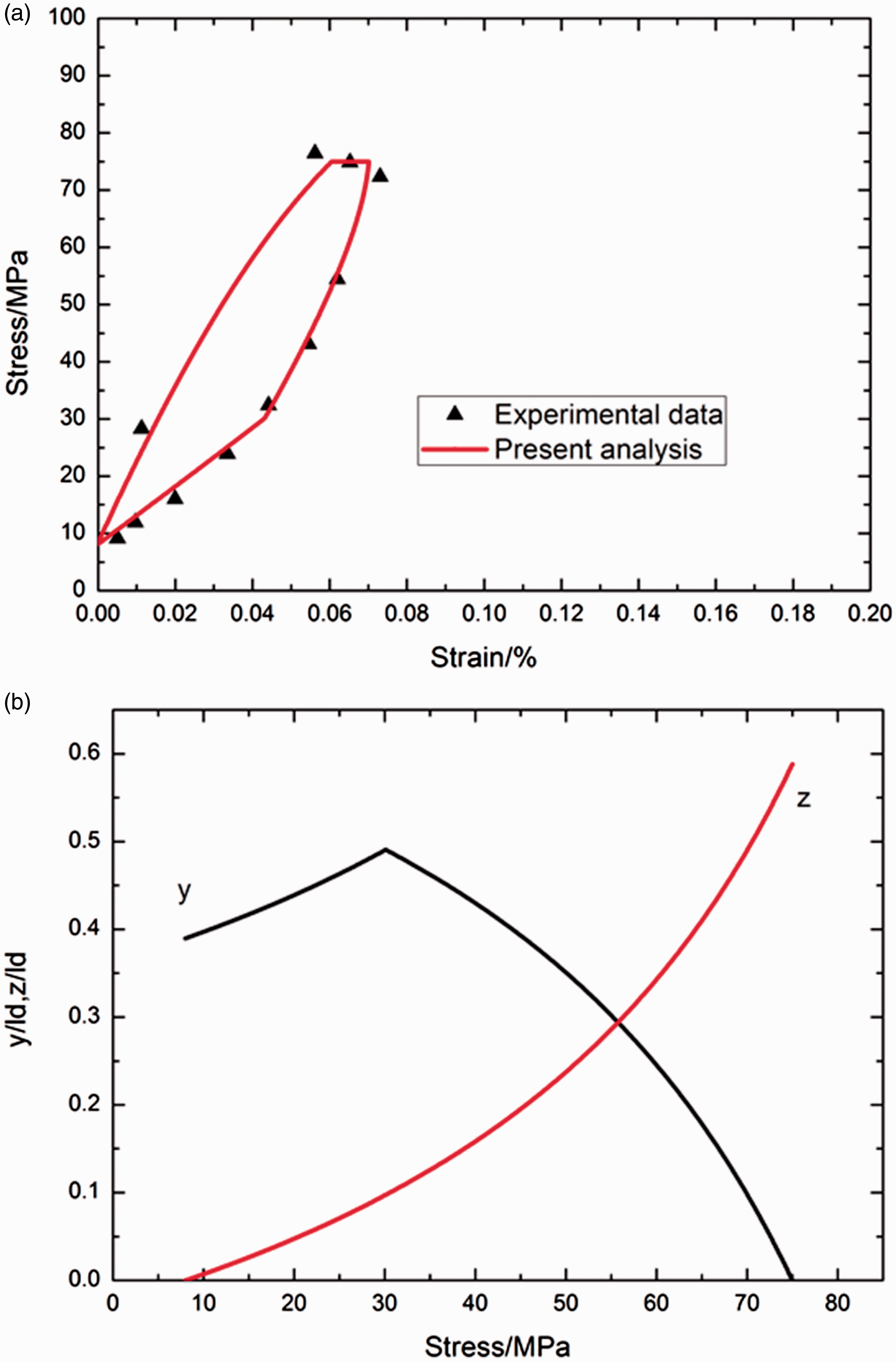
When σmax = 75 MPa, the fatigue hysteresis loops correspond to the interface partially debonding and the fiber partially sliding relative to the matrix in the interface debonded region, as shown in Figure 10(a); and upon unloading to the valley stress of σmin = 7.5 MPa, the interface counter slip length approaches to 38.9% of the interface debonded length, i.e., y(σmin)/ld = 0.389, and upon reloading to the peak stress of σmax = 75 MPa, the interface new slip length approaches to 58.8% of the interface debonded length, i.e., z(σmax)/ld = 0.588, as shown in Figure 10(b).
When σmax = 100 MPa, the fatigue hysteresis loops correspond to the interface partially debonding and the fiber partially sliding relative to the matrix in the interface debonded region, as shown in Figure 11(a); and upon unloading to the valley stress of σmin = 10 MPa, the interface counter slip length approaches to 58.1% of the interface debonded length, i.e., y(σmin)/ld = 0.581, and upon reloading to the peak stress of σmax = 100 MPa, the interface new slip length approaches to 63.5% of the interface debonded length, i.e., z(σmax)/ld = 0.635, as shown in Figure 11(b).
Conclusions
In this paper, comparisons of thermomechanical fatigue hysteresis loops of fiber-reinforced CMCs subjected to different phase angles of θ = 0, π/3, π/2, and π have been investigated. The shape, location and area of the fatigue hysteresis loops are affected by the phase angles under thermomechanical cyclic loading. The fatigue hysteresis loops of cross-ply SiC/MAS composite under the phase angles of θ = 0 and π have been predicted for different fatigue peak stresses and cycle numbers. The effects of fiber volume fraction, fatigue peak stress, matrix crack spacing, interface frictional coefficient and interface debonded energy on the thermomechanical fatigue hysteresis loops of different phase angles have been analyzed.
With the increasing fiber volume fraction, the fatigue hysteresis loops area decreases; the unloading strain at the valley stress decreases; the fiber/matrix interface slip lengths at the phase angles of θ = π/3, π/2, and π increase, and decreases at the phase angle of θ = 0. With the increasing fatigue peak stress, the fatigue hysteresis loops area increases; the unloading strain at the valley stress increases; the fiber/matrix interface slip lengths at the phase angles of θ = π/3, π/2, and π decrease, and increases at the phase angle of θ = 0. With the increasing matrix crack spacing, the fatigue hysteresis loops area decreases; the unloading strain at the valley stress decreases; the fiber/matrix interface slip lengths at the phase angles of θ = 0, π/3, π/2, and π decrease. With the increasing interface frictional coefficient, the area of fatigue hysteresis loops decreases; the unloading strain at the valley stress decreases at the phase angles of θ = π/3, π/2, and π, and increases at the phase angle of θ = 0; the fiber/matrix interface slip lengths at the phase angles of θ = 0, π/3, and π/2 decrease, and increases at the phase angle of θ = π. With the increasing interface debonded energy, the area of fatigue hysteresis loops increases; the unloading strain at the valley stress decreases; the fiber/matrix interface slip lengths at the phase angles of θ = 0, π/3, π/2, and π increase.
Footnotes
Acknowledgements
The author wishes to thank two anonymous reviewers and editors for their helpful comments on an earlier version of the paper.
Declaration of Conflicting Interests
The author(s) declared no potential conflicts of interest with respect to the research, authorship, and/or publication of this article.
Funding
The author(s) disclosed receipt of the following financial support for the research, authorship, and/or publication of this article: The work reported here is supported by the Natural Science Fund of Jiangsu Province (grant no. BK20140813), and the Fundamental Research Funds for the Central Universities (grant no. NS2016070).